Toyota Corolla (2004+). Manual - part 108

61-13
SEAT BELT
- FRONT SEAT BELT
(e) Dispose of the front seat outer belt (with seat belt preten-
sioner).
CAUTION:
F
The rear outer belt is very hot when the seat belt pre-
tensioner is activated, so leave it alone for at least 30
minutes after activation.
F
Use gloves and safety glasses when handling a front
seat outer belt with activated seat belt pretensioner.
B51516
F
Always wash your hands with water after completing
the operation.
F
Do not apply water, etc. to a front seat outer belt with
activated seat belt pretensioner.
(1)
Remove the disc wheel and SST.
(2)
Place the front seat outer belt in a vinyl bag, tie the
end tightly and dispose of it in the same way as oth-
er general parts.

61-5
SEAT BELT
- FRONT SEAT BELT
FRONT SEAT BELT
610FO-01
PRECAUTION
CAUTION:
Replace the faulty parts of the seat belt systems (outer belt, inner belt, bolts, nuts, adjustable
shoul-
der anchor, tether anchor hardware, sill-bar, etc.).
Seat belt systems not in use at the time of a collision should also be inspected and replaced if found
to be damaged or working improperly.
1.
RUNNING TEST
(a) Fasten the front seat belts.
(b) Drive the vehicle at 16 km/h (10 mph) and slam on the
brakes. Check that the belt locks and cannot be extended
at this time.
HINT:
Conduct this test in a safe area. If the belt does not lock, remove
the belt assembly and perform the inspections. Also whenever
B69710
installing a new belt assembly, verify the proper operation be-
fore installation.

61-7
SEAT BELT
- FRONT SEAT BELT
61085-02
REPLACEMENT
HINT:
F
Installation is in the reverse order of the removal. But the installation is indicated only when it has a
point.
F
In the LH side, work in the same procedure as in the RH side.
1.
DISCONNECT BATTERY NEGATIVE TERMINAL
2.
REMOVE FRONT SEAT ASSEMBLY RH (See page 72-2)
3.
REMOVE FRONT SEAT INNER BELT ASSY RH
(a) Remove the nut and front seat inner belt.
4.
REMOVE FRONT DOOR SCUFF PLATE RH (See page 76-21)
5.
REMOVE REAR DOOR SCUFF PLATE RH (See page 76-21)
6.
REMOVE FRONT DOOR OPENING TRIM RH
7.
REMOVE REAR DOOR OPENING TRIM RH
8.
REMOVE CENTER PILLAR GARNISH LOWER RH (See page 76-21)
9.
REMOVE FRONT SEAT OUTER BELT ASSY RH
Protective Tape
(a) Remove the floor anchor cover.
Claw
(b) Remove the bolt and disconnect the front seat outer belt
assembly RH (floor anchor side).
(c)
Using a screwdriver, remove the seat belt anchor cover.
HINT:
Tape the screwdriver tip before use.
(d) Remove the bolt and front seat outer belt (shoulder an-
B55754
chor side).
NOTICE:
F
Removal operation of the seat belt with pretensioner
must be started in 90 seconds or more after the igni-
tion switch is tur ned OFF and the battery negative ter-
minal is disconnected.
F
Carefully read the notices for the ”pretensioner” in
the SRS airbag system and front seat outer belt as-
sembly.
B50195
B57295
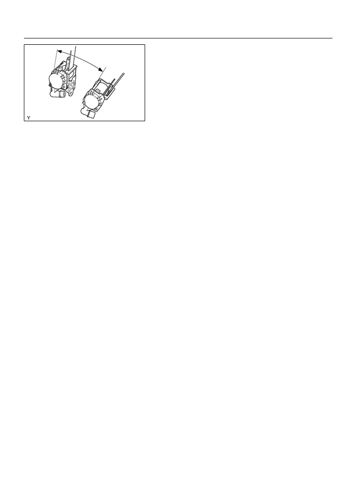
(e) Disconnect the connector and remove the bolt.
10. REMOVE CENTER PILLAR GARNISH RH (See page 76-21)
11. REMOVE FRONT SHOULDER BELT ANCHOR ADJUSTER ASSY
(a) Remove the 2 bolts and front shoulder belt anchor adjuster assembly.
12. INSTALL FRONT SHOULDER BELT ANCHOR ADJUSTER ASSY
(a) Install the front shoulder belt anchor adjuster assembly with the bolt.
Torque: 41.2 N m (420 kgf cm, 30 ft lbf)
61-8
SEAT BELT
- FRONT SEAT BELT
13. INSTALL FRONT SEAT OUTER BELT ASSY RH
45_
NOTICE:
Unlock
Do not disassemble the retractor.
(a) Check the degree of tilt when beginning to lock the ELR.
(1)
Check that the belt will not lock within 15 degrees of
tilt in all the direction but the belt will lock over 45 de-
grees of tilt when moving the installed retractor
Lock
gently.
B50563
If the operation is not as specified, replace the front seat outer
belt assembly.
(b) Install the retractor with the 2 bolts.
Torque:
4.9 Nm (50 kgf cm, 43 in. lbf) (Upper part of retractor)
41.2 Nm (420 kgf cm, 30 ft lbf) (Lower part of retrac-
tor)
(c)
Install the shoulder anchor with the bolt.
Torque: 41.2 N m (420 kgf cm, 30 ft lbf)
(d) Install the seat belt anchor cover.
(e) Install the floor anchor with the bolt.
Torque: 41.2 N m (420 kgf cm, 30 ft lbf)
(f)
Install the floor anchor cover.
(g) Check the ELR lock.
NOTICE:
Check should be performed with the assembly installed.
(1)
Check that the belt will lock when pulling out the belt
quickly with the belt installed.
If the operation is not as specified, replace the front seat outer
belt assembly.
14.
INSTALL FRONT SEAT INNER BELT ASSY RH
(a)
Install the front seat inner belt assembly RH with the nut.
Torque: 41.2 N m (420 kgf cm, 30 ft lbf)

61-3
SEAT BELT
- SEAT BELT WARNING SYSTEM
61083-02
INSPECTION
1.
INSPECT FRONT SEAT INNER BELT ASSY LH
Connector
B6
(For Airbag Sensor)
(a) When fastening the seat belt (buckle switch ON).
(1)
Inspect the continuity and resistance between the
terminals.
3
2
1
Standard:
2
1
Terminal No.
Specified condition
6
5
4
B6-1 B6-2
1,330 W
B6-1 B6-3
No continuity
B59902
B6-4 2
Continuity
B6-5 1
Continuity
If the result is not as specified, replace the inner belt.
(b) When releasing the seat belt (buckle switch OFF).
Connector
B6
(For Airbag Sensor)
(1)
Inspect the continuity and resistance between the
terminals.
Standard:
3
2
1
Terminal No.
Specified condition
2
1
B6-1 B6-2
330 W
6
5
4
B6-1 B6-3
Continuity
B6-4 2
Continuity
B6-5 1
Continuity
B59902
If the result is not as specified, replace the inner belt.
2.
INSPECT FRONT SEAT INNER BELT ASSY RH
Connector
(a) Short between connector terminals 1 and 2 for the oc-
(For Occupation Detection Sensor)
cupation detection sensor (seat is occupied).
1
2
B59296
(b) When fastening the seat belt (buckle switch is ON and
B7
seat is occupied).
(1)
Inspect the continuity between the terminals of the
connector for the warning switch.
Standard:
4 3 2 1
Terminal No.
Specified condition
B7-3 B7-4
Continuity
B7-1 B7-4
No continuity
B59297

61-4
SEAT BELT
- SEAT BELT WARNING SYSTEM
(c)
When releasing the seat belt (buckle switch is OFF and
B7
seat is occupied).
(1)
Inspect the continuity between the terminals of the
connector for the warning switch.
Standard:
4 3 2 1
Terminal No.
Specified condition
B7-3 B7-4
Continuity
B7-1 B7-2
Continuity
B59297
(d) Disconnect the occupation detection sensor connector
Connector
(seat is not occupied).
(For Occupation Detection Sensor)
1
2
B59296
(e) When fastening the seat belt (buckle switch is not ON and
B7
seat is occupied).
(1)
Inspect the continuity between the terminals of the
connector for the warning switch.
4 3 2 1
Standard:
Terminal No.
Specified condition
B7-3 B7-4
No continuity
B7-1 B7-2
No continuity
B59297
(f)
When releasing the seat belt (buckle switch is not OFF
B7
and seat is occupied).
(1)
Inspect the continuity between the terminals of the
connector for the warning switch.
4 3 2 1
Standard:
Terminal No.
Specified condition
B7-3 B7-4
No continuity
B7-1 B7-2
Continuity
B59297
If the result is not as specified, replace the inner belt.

61-1
SEAT BELT
- SEAT BELT WARNING SYSTEM
SEAT BELT WARNING SYSTEM
61081-02
LOCATION
Combination Meter (Driver’s Seat Belt Warning Lamp)
Passenger’s Seat Belt Warning Lamp Assy
Seat Belt Warning Sensor
Front Seat Inner Belt Assy LH
Front Seat Inner Belt Assy RH
B59294

61-14
SEAT BELT
- REAR SEAT BELT
REAR SEAT BELT
61086-02
COMPONENTS
Fixed Type Rear Seat
Rear Seat Side Cover RH
Package Tray
41.2 (420, 30)
Trim Panel Assy
Roof Side
Garnish
Inner RH
Separated Type
Rear Seat
Room Partition
41.2 (420, 30)
Board RH
Rear Seat 3 Point
Belt Assy Outer
Rear Seat
41.2 (420, 30)
Inner
Roof Side
w/ Center
Garnish Inner LH
Belt Assy LH
Rear Door Opening
Trim RH
41.2 (420, 30)
Rear Door
Rear Seat Inner
Opening Trim LH
w/ Center Belt
Assy RH
Room Partition
Board LH
Separated
Type
Rear Seat
Rear Seat
Back Assy
Rear Seat
Rear Seat Side Cover LH
Cushion Assy
Nm (kgfcm ftlbf)
: Specified torque
B59291

61-15
SEAT BELT
- REAR SEAT BELT
61087-02
REPLACEMENT
HINT:
Installation is in the reverse order of the removal. But the installation is indicated only when it has a point.
1.
REMOVE REAR DOOR OPENING TRIM RH
2.
REMOVE REAR DOOR OPENING TRIM LH
3.
REMOVE REAR SEAT CUSHION ASSEMBLY (See page 72-6 or 72-8)
4.
REMOVE REAR SEAT BACK ASSY (FIXED TYPE REAR SEAT) (See page
72-8)
5.
REMOVE REAR SEAT BACK ASSY (SEPARATED TYPE REAR SEAT) (See page
72-6)
6.
REMOVE REAR SEAT SIDE COVER RH (FIXED TYPE REAR SEAT) (See page 76-21)
7.
REMOVE REAR SEAT SIDE GARNISH LH (FIXED TYPE REAR SEAT) (See page 76-21)
8.
REMOVE ROOM PARTITION BOARD LH (SEPARATED TYPE REAR SEAT)
(See page 76-21)
9.
REMOVE ROOM PARTITION BOARD RH (SEPARATED TYPE REAR SEAT)
(See page 76-21)
10. REMOVE ROOF SIDE GARNISH INNER RH (See page 76-21)
11. REMOVE ROOF SIDE GARNISH INNER LH (See page 76-21)
12. REMOVE PACKAGE TRAY TRIM PANEL ASSY
(a) Pull out the belt from the slit, and then remove the pack-
age tray trim panel assembly.
B59276
13. REMOVE REAR SEAT 3 POINT TYPE BELT ASSY OUTER
(a) Remove the bolt and disconnect the rear seat 3 point type belt assembly outer (floor anchor).
(b) Remove the bolt and rear seat 3 point type belt assembly outer.
14. REMOVE REAR SEAT INNER W/CENTER BELT ASSY RH
(a) Remove the 2 bolts and rear seat inner w/ center belt assembly RH.
15. REMOVE REAR SEAT INNER W/CENTER BELT ASSY LH
(a) Remove the bolt and rear seat inner w/ center belt assembly LH.
16. REMOVE CHILD RESTRAINT SEAT ANCHOR BRACKET SUB-ASSY RH
(a) Remove the 2 bolts and child restraint seat anchor bracket RH.
17. INSTALL CHILD RESTRAINT SEAT ANCHOR BRACKET SUB-ASSY RH
(a) Install the child restraint seat anchor bracket RH with the 2 bolts.
Torque: 18.1 N m (185 kgf cm, 13.3 ft lbf)

61-16
SEAT BELT
- REAR SEAT BELT
18. INSTALL REAR SEAT INNER W/CENTER BELT ASSY
Protrusion Part
LH
(a) Install the rear seat inner w/ center belt assembly RH with
the bolt, as shown in the illustration.
Front
Torque: 41.2 N m (420 kgf cm, 30 ft lbf)
Mark
Front
NOTICE:
F
Do not make the anchor part run onto the protrusion
part of the floor panel.
Protrusion Part
B58711
F
Do not disassemble the retractor.
(b) Check the degree of tilt when the belt begins to lock the
Unlock
ELR.
(1)
Check that the belt will not lock within 15 degrees of
tilt in all the direction but the belt will lock over 45 de-
45_
grees of tilt when moving the installed retractor
gently.
If the operation is not as specified, replace the rear seat belt as-
sembly outer center.
Lock
B50564
(c)
Install the rear seat belt assembly outer center with the
bolt.
Torque: 41.2 N m (420 kgf cm, 30 ft lbf)
(d) Check the ELR lock.
NOTICE:
Check should be performed with the assembly installed.
(1)
Check that the belt will lock when pulling out the belt
quickly with the belt installed.
If the operation is not as specified, replace the rear seat belt as-
sembly outer center.
(e) Check the fastening function of the child restraint system.
NOTICE:
Check should be performed with the assembly installed.
(1)
Check that the belt cannot be pulled out any more
but can be rewound after the belt is fully pulled out.
(2)
Check that the belt can be pulled out and rewound
after the belt is fully rewound.
If the operation is not as specified, replace the rear seat belt as-
sembly outer center.
19. INSTALL REAR SEAT INNER W/CENTER BELT ASSY
Protrusion Part
RH
(a) Install the rear seat inner w/ center belt assembly RH with
the bolt, as shown in the illustration.
Front
Torque: 41.2 N m (420 kgf cm, 30 ft lbf)
Mark
Front
NOTICE:
Do not make the anchor part run onto the protrusion part
Protrusion Part
of the floor panel.
B59304

61-17
SEAT BELT
- REAR SEAT BELT
20. INSTALL REAR SEAT 3 POINT TYPE BELT ASSY
Unlock
OUTER
NOTICE:
Do not disassemble the retractor.
45_
(a) Check the degree of tilt when the belt begins to lock the
ELR.
(1)
Check that the belt will not lock within 15 degrees of
tilt in all the direction but the belt will lock over 45 de-
Lock
B50564
grees of tilt when moving the installed retractor
gently.
If the operation is not as specified, replace the rear seat belt as-
sembly outer.
(b) Install the rear seat belt assembly outer (retractor side)
with the bolt.
Torque: 41.2 N m (420 kgf cm, 30 ft lbf)
(c)
Install the rear seat belt assembly outer (floor anchor
Protrusion
side) with the bolt.
Torque: 41.2 N m (420 kgf cm, 30 ft lbf)
NOTICE:
Do not make the anchor part run onto the protrusion part
40
10_
of the floor panel.
(d) Check the ELR lock.
NOTICE:
Protrusion
B58622
Check should be performed with the assembly installed.
(1)
Check that the belt will lock when pulling out the belt
quickly with the belt installed.
If the operation is not as specified, replace the rear seat belt as-
sembly outer.
(e) Check the fastening function of the child restraint system.
NOTICE:
Check should be performed with the assembly installed.
(1)
Check that the belt cannot be pulled out any more
but can be rewound after the belt is fully pulled out.
(2)
Check that the belt can be pulled out and rewound
after the belt is fully rewound.
If the operation is not as specified, replace the rear seat belt as-
sembly outer.
21.
INSTALL ROOM PARTITION BOARD RH (SEPARATED TYPE REAR SEAT)
22.
INSTALL ROOM PARTITION BOARD LH (SEPARATED TYPE REAR SEAT)
23.
INSTALL REAR SEAT SIDE GARNISH LH (FIXED TYPE REAR SEAT)
24.
INSTALL REAR SEAT SIDE COVER RH (FIXED TYPE REAR SEAT)
25.
INSTALL REAR SEAT BACK ASSY (FIXED TYPE REAR SEAT) (See page
72-8)
26.
INSTALL REAR SEAT BACK ASSY (SEPARATED TYPE REAR SEAT) (See page
72-6)

61-2
SEAT BELT
- SEAT BELT WARNING SYSTEM
61082-02
PROBLEM SYMPTOMS TABLE
Symptom
Suspected Area
See page
1. GAUGE fuse
2. Combination meter
71-17
Driver’s seat belt warning lamp does not light up
3. Airbag sensor assembly center
60-38
4. Front seat inner belt assembly LH
61-3
5. Wire harness
1. GAUGE fuse
2. Passenger’s seat belt warning lamp
61-3
Passenger’s seat belt warning lamp does not light up
3. Front seat inner belt assembly RH
61-3
4. Wire harness

65-15
LIGHTING
- LH HEADLAMP ASSY
650GT-01
ADJUSTMENT
1.
HEADLIGHT AIM ONLY
(a) Place the vehicle in the following conditions.
_
The area around the headlight is not deformed.
_
The vehicle is parked on a level surface.
_
Tire inflation pressure is in the specified value (See page 28-1).
_
A driver is in the driver’s seat and the vehicle is in a state ready for driving (with a tank full).
_
The vehicle has been bounced several times.
(b) Check the headlight aiming.
(1)
Prepare a thick white paper.
(2)
Stand the paper perpendicular to the ground at the position 9.84 ft away from the headlights.
(3)
Ensure that the center line of the vehicle and the paper face forms a 90-degree angle as shown
in the illustration.
(4)
Draw a horizontal line (H line) on the paper, showing where the headlights should strike.
(5)
Draw a vertical line (V line) to where the center line of the vehicle is to be.
(6)
Draw 2 vertical lines to where the both headlights should strike (V RH and V LH lines).
(7)
Draw a horizontal line (by connecting the both low beam center marks) to where the headlights
should strike (H RH and H LH lines).
(8)
Take appropriate measures to prevent any influence of other lights.
(9)
Set the headlights leveling position to ”0” position and adjust the angle of the headlight axis.
HINT:
The H RH and H LH line is 0.4° below the horizontal line (H line) of the light axis.
(10) Start the engine.
(11) Turn the headlights ON.
(12) Check that the headlights properly strike the position shown in the illustration.
(13) If not, adjust the lights in the vertical direction.
High Beam:
Low Beam:
6
5
6
20.9 mm
4
(0.82 in)
20.9 mm
V LH Line V Line V RH Line
H
(0.82 in)
0.4f
20.9 mm
3 m (9.84 ft)
940mm (37.01in.)
(0.82 in)
Low Beam:
Vehicle Position:
6
5
6
V RH
V LH Line V Line
V RH Line
Line
90f
H RH and
V LH
7
H LH lines
Line
20.9 mm
1,210mm (47.64in.)
(0.82 in)
:
Step No.
E60707

65-16
LIGHTING
- LH HEADLAMP ASSY
HINT:
_
As shown in the illustration, adjust each aim of the RH and LH lights.
(c)
When adjusting the headlight aim in the veatical direction:
Using adjusting bolt, adjust the headlight aim to be within
the specified range.
HINT:
The optical aim moves upward when turning a screwdriver
clockwise, while it moves downward when turning a screwdriver
counterclockwise.
E60620

65-21
LIGHTING
- BACK UP LAMP ASSY LH
BACK UP LAMP ASSY LH
650GY-01
REPLACEMENT
1.
REMOVE BACK UP LAMP ASSY LH
(a) Remove the service hole cover.
(b) Remove the 2 nuts and disconnect the connector.
E60613
(c)
Using a mouldingremover, remove the 2 clips and back
up light assy LH.
Clip
E60614
2.
INSTALL BACK UP LAMP ASSY LH
(a) Set the 2 clips on the back up light assy LH as shown in
the illustration.
(b) Connect the connector.
(c)
Install the back up light LH with 2 nuts.
E60460