Toyota Corolla (2004+). Manual - part 106

60-9
SUPPLEMENTAL RESTRAINT SYSTEM
- SUPPLEMENTAL RESTRAINT SYSTEM
3.
HORN BUTTON ASSY(VEHICLE INVOLVED IN COLLISION AND AIRBAG IS DEPLOYED)
(a) Check the diagnostic system (See page 05-424).
(b) Visually check the following item with the horn button assy (with airbag) removed from the vehicle.
Check the damage on the spiral cable connector and wire harness.
HINT:
There should be no interference between the horn button assy and steering wheel, and the clearance should
be uniform all the way around when the new horn button assy is installed on the steering wheel.
4.
INSTRUMENT PANEL PASSENGER AIRBAG
ASSY(VEHICLE NOT INVOLVED IN COLLISION)
(a) Check the diagnostic system (See page 05-424).
(b) Visually check the following item with the instrument pan-
el passenger airbag assy installed in the vehicle.
Check cuts, minute cracks or marked discoloration on the
instrument panel passenger airbag assy and instrument
panel.
H42043
5.
INSTRUMENT PANEL PASSENGER AIRBAG
ASSY(VEHICLE INVOLVED IN COLLISION AND AIR-
BAG IS NOT DEPLOYED)
(a) Check the diagnostic system (See page 05-424).
(b) Visually check the following items with the instrument
panel passenger airbag assy removed from the vehicle.
F
Check cuts, minute cracks or marked discoloration
on the instrument panel passenger airbag assy.
H42044
F
Check cuts and cracks in wire harness, and for chip-
ping in connectors.
F
Check the deformation or cracks on the instrument
panel and instrument panel reinforcement.
HINT:
If the instrument panel or instrument panel reinforcement is de-
formed or cracked, never repair it. Always replace it with a new
one.
CAUTION:
For removal and installation of the instrument panel pas-
senger airbag assy, see page
60-25, and be sure to follow
the correct procedure.
H42043

60-10
SUPPLEMENTAL RESTRAINT SYSTEM
- SUPPLEMENTAL RESTRAINT SYSTEM
6.
INSTRUMENT PANEL PASSENGER AIRBAG ASSY(VEHICLE INVOLVED IN COLLISION AND
AIRBAG IS DEPLOYED)
(a) Check the diagnostic system (See page 05-424).
(b) Visually check the following items with the instrument panel passenger airbag assy removed from the
vehicle.
F
Check the deformation or cracks on the instrument panel and instrument panel reinforcement.
F
Check the damage on the connector and wire harness.
HINT:
If the instrument panel or instrument panel reinforcement is deformed or cracked, never repair it. Always
replace it with a new one.
7.
FRONT SEAT AIRBAG A SSY(VEHICLE NOT IN-
VOLVED IN COLLISION)
(a) Check the diagnostic system (See page 05-424).
(b) Visually check the following item with the front seat airbag
assy installed in the vehicle.
Check cuts, minute cracks or marked discoloration on the
front seat airbag assy and the front seat assy.
H42042
8.
FRONT SEAT AIRBAG ASSY(VEHICLE INVOLVED IN
COLLISION AND AIRBAG IS NOT DEPLOYED)
(a) Check the diagnostic system (See page 05-424).
(b) Visually check the following items with the front seat air-
bag assy removed from the front seat assy.
F
Check cuts, minute cracks or marked discoloration
on the front seat airbag assy.
F
Check cuts and cracks in wire harness, and for chip-
H41401
ping in connectors.
9.
AIRBAG SENSOR ASSY CENTER(VEHICLE NOT INVOLVED IN COLLISION)
(a)
Check the diagnostic system (See page 05-424).
10.
AIRBAG SENSOR ASSY CENTER(VEHICLE INVOLVED IN COLLISION AND AIRBAG IS NOT
DEPLOYED)
(a)
Check the diagnostic system (See page 05-424).
11.
AIRBAG SENSOR ASSY CENTER(VEHICLE INVOLVED IN COLLISION AND AIRBAG IS
DEPLOYED)
(a)
Replace the airbag sensor assy center (See page 60-38).

60-11
SUPPLEMENTAL RESTRAINT SYSTEM
- SUPPLEMENTAL RESTRAINT SYSTEM
12. AIRBAG FRONT SENSOR(VEHICLE NOT INVOLVED
IN COLLISION)
(a) Check the diagnostic system (See page 05-424).
13. AIRBAG FRONT SENSOR(VEHICLE INVOLVED IN
COLLISION)
(a) Check the diagnostic system (See page 05-424).
(b) If the front fender of the car or its periphery is damaged,
Visually check for damage to the airbag front sensor,
H42122
which includes the following items even if the airbag was
not deployed:
F
Cracks, dents or chips in the case
F
Cracks, dents, chipping and scratches in the con-
nector
F
Peeling off of the label or damage to the serial num-
ber
H41961
14. SIDE AIRBAG SENSOR ASSY(VEHICLE NOT INVOLVED IN COLLISION)
(a) Check the diagnostic system (See page 05-424).
15. SIDE AIRBAG SENSOR A SSY(VEHICLE INVOLVED IN COLLISION AND AI RBAG IS NOT
DEPLOYED)
(a) Check the diagnostic system (See page 05-424).
16. SIDE AIRBAG SENSOR ASSY(VEHICLE INVOLVED IN COLLISION AND AIRBAG IS DEPLOYED)
(a) Replace the front seat airbag assy and side airbag sensor assy (See page 60-44, 72-2).
17. SEAT POSITION AIRBAG SENSOR(VEHICLES NOT INVOLVED IN COLLISION)
(a) Check the diagnostic system (See page 05-424).
18. SEAT POSITION AIRBAG SENSOR(VEHICLE INVOLVED IN COLLISION)
(a) Check the diagnostic system (See page 05-424).
(b) Visually check for damage to the seat position airbag sensor, which includes the following items even
if the airbag was not deployed:
F
Cracks, dents or chips in the case
F
Cracks, dents, chipping and scratches in the connector
19. WIRE HARNESS AND CONNECTOR(VEHICLE NOT INVOLVED IN COLLISION)
(a) Check the diagnostic system (See page 05-424).
20. WIRE HARNESS AND CONNECTOR(VEHICLE INVOLVED IN COLLISION)
(a) Check the diagnostic system (See page 05-424).
(b) Check breaks in all wires of the SRS wire harness, and exposed conductors.
(c)
Check to see if the SRS wire harness connectors are cracked or chipped.
HINT:
The SRS wire harness is integrated with the instrument panel wire harness assembly. All the connectors in
the system are standard yellow.
60-24
SUPPLEMENTAL RESTRAINT SYSTEM
- INSTRUMENT PANEL PASSENGER AIR BAG ASSY
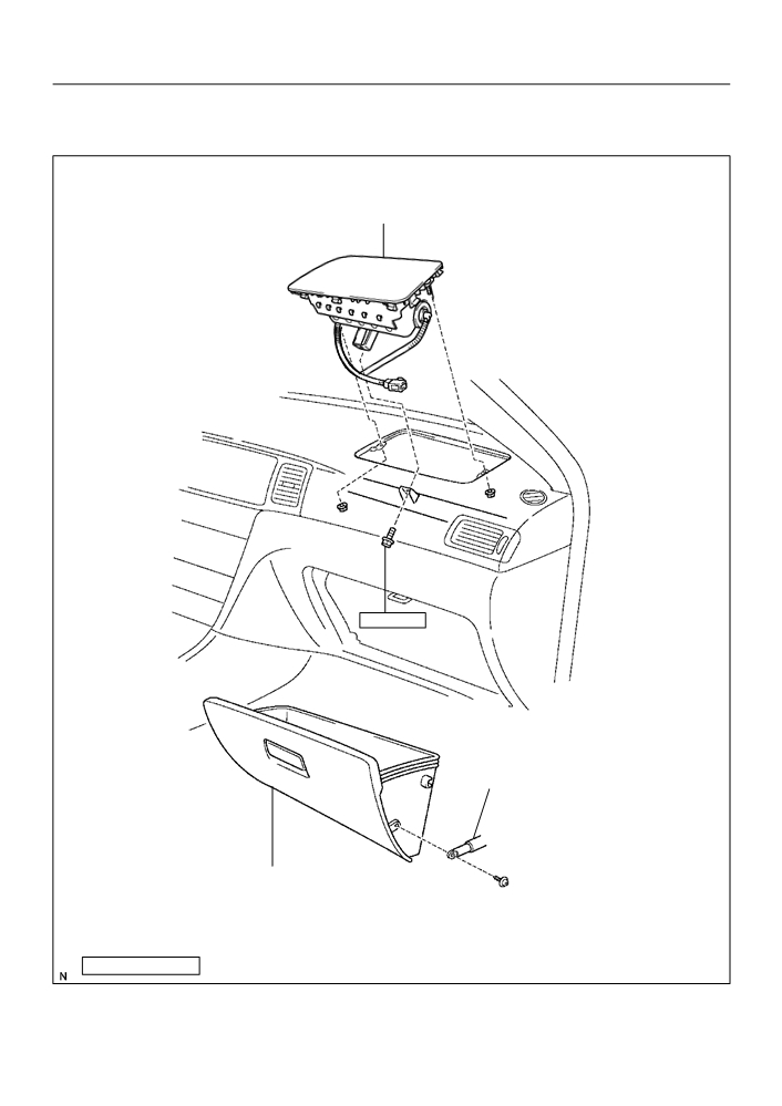
INSTRUMENT PANEL PASSENGER AIR BAG ASSY
600C0-01
COMPONENTS
Instrument Panel Passenger Airbag Assy
20 (204, 15)
Glove Compartment Door
Stopper Sub-Assy
Instrument Panel Sub-Assy Lower
Nm(kgfcm, ftlbf)
: Specified torque
H42046

60-26
SUPPLEMENTAL RESTRAINT SYSTEM
- INSTRUMENT PANEL PASSENGER AIR BAG ASSY
600C2-02
DISPOSAL
HINT:
When scrapping vehicle equipped with an SRS or disposing of a instrument panel passenger airbag assy,
always first deploy the airbag in accordance with the procedure described below. If any abnormality occurs
with the airbag deployment, contact the SERVICE DEPT. of TOYOTA MOTOR SALES, U.S.A., INC.
CAUTION:
F
Never dispose of a instrument panel passenger air-
bag assy which has an undeployed airbag.
F
The airbag produces a sizeable exploding sound
when it deploys, so perform the operation out of
doors and the place where it will not create a nuisance
to nearby residents.
F
When deploying the airbag, always use the specified
SST (SRS Airbag Deployment Tool). Perform the op-
eration in a place away from electrical noise.
F
When deploying an airbag, perform the operation at
SST
least 10 m (33 ft) away from the instrument panel pas-
senger airbag assy.
F
The instrument panel passenger airbag assy is very
hot when the airbag is deployed, so leave it alone for
H40004
at least 30 minutes after deployment.
F
Use gloves and safety glasses when handling a
instrument panel passenger airbag assy with the
deployed airbag.
F
Always wash your hands with water after completing
the operation.
F
Do not apply water, etc. to a instrument panel passen-
ger airbag assy with the deployed airbag.
1.
DISPOSE INSTRUMENT PANEL PASSENGER AIR
BAG ASSY
(WHEN SCRAPPING VEHICLE
DEPLOYMENT METHOD)
HINT:
Prepare a battery for the power source to deploy the airbag.
(a) Check the function of SST (See step 1-(a) on page
60-14).
H40005

60-27
SUPPLEMENTAL RESTRAINT SYSTEM
- INSTRUMENT PANEL PASSENGER AIR BAG ASSY
(b) Disconnect the airbag connector.
(1)
Remove the instrument panel sub-assy lower.
NOTICE:
When handling the airbag connector, take care not to dam-
age the airbag wire harness.
(2)
Disconnect the airbag connectors.
H42049
(c)
Set SST.
(1)
Connect the connectors of the 2 SST to the instru-
ment panel passenger airbag assy connectors.
SST
09082-00700, 09082-00780
NOTICE:
To avoid damaging the SST connector and wire harness,
do not lock the secondary lock of the twin lock.
SST
H42047
(2)
Move the SST at least 10 m (33 ft) away from the
front of the vehicle.
(3)
Close all the doors and windows of the vehicle.
NOTICE:
Battery
Take care not to damage the SST wire harness.
(4)
Connect the red clip of the SST to the battery posi-
SST
tive (+) terminal and the black clip to the negative (-)
10 m (33 ft) or more
terminal.
H40007
(d) Deploy the airbag.
(1)
Check that no one is inside the vehicle or within 10
m (33 ft) area around the vehicle.
(2)
Press the SST activation switch and deploy the air-
bag.
HINT:
The airbag deploys simultaneously when the LED of the SST
activation switch lights up.
(e) Dispose the instrument panel passenger airbag assy.
CAUTION:
F
The instrument panel passenger airbag assy is very
hot when the airbag is deployed, so leave it for at least
30 minutes after deployment.
F
Use gloves and safety glasses when handling a
instrument panel passenger airbag assy with the
deployed airbag.
F
Always wash your hands with water after completing
the operation.
F
Do not apply water, etc. to a instrument panel passen-
ger airbag assy with the deployed airbag.

60-28
SUPPLEMENTAL RESTRAINT SYSTEM
- INSTRUMENT PANEL PASSENGER AIR BAG ASSY
F
When moving a vehicle for scrapping which has a
instrument panel passenger airbag assy with the
deployed airbag, use gloves and safety glasses.
HINT:
When scrapping a vehicle, deploy the airbag and scrap the ve-
hicle with the instrument panel passenger airbag assy being
installed.
2.
DISPOSE INSTRUMENT PANEL PASSENGER AIR
BAG ASSY (WHEN DISPOSING OF AIRBAG
ASSEMBLY DEPLOYMENT METHOD)
NOTICE:
F
When disposing of the instrument panel passenger
airbag assy only, never use the customer’s vehicle to
deploy the airbag.
F
Be sure to follow the procedure given below when de-
ploying the airbag.
HINT:
Prepare a battery for the power source to deploy the airbag.
(a) Remove the instrument panel passenger airbag assy
(See page 60-25).
CAUTION:
F
When removing the instrument panel passenger air-
bag assy, work must be started 90 seconds after the
ignition switch is turned to the ”LOCK” position and
the negative (-) terminal cable is disconnected from
the battery.
H42044
F
Store the instrument panel passenger airbag assy
with the airbag deployment side facing upward.
(b) Using a service-purpose wire harness for the vehicle, tie
Wire Harness
down the instrument panel passenger airbag assy to the
Diameter
tire.
Wire harness: Stripped wire harness section
1.25 mm 2 or more (0.0019 in. 2 or more)
CAUTION:
If the instrument panel passenger airbag assy is tied
down
with too thin wire harness, it may snap. This is highly dan-
Stripped Wire Harness Section
H40008
gerous. Always use a wire harness which is at least 1.25
mm 2 (0.0019 in. 2).
HINT:
To calculate the area of the stripped wire harness section:
Area = 3.14 X (Diameter) 2 divided by 4

60-29
SUPPLEMENTAL RESTRAINT SYSTEM
- INSTRUMENT PANEL PASSENGER AIR BAG ASSY
(1)
Install the 2 nuts to the instrument panel passenger
airbag assy.
H42023
(2)
Wind the wire harness around the brackets, as
shown in the illustration.
(3)
Position the instrument panel passenger airbag
assy inside the tire with the airbag deployment side
facing inside.
Tire size: Must exceed the following dimensions-
Width: 185 mm (7.28 in.)
Inner diameter: 360 mm (14.17 in.)
H42024
CAUTION:
F
Make sure that the wire harness is tight. It is very dangerous if the loosened wire harness re-
sults in the instrument panel passenger airbag assy coming free due to the shock from the air-
bag deployment.
F
Always tie down the instrument panel passenger airbag assy with the airbag deployment side
facing inside.
NOTICE:
The tire will be marked by the airbag deployment, so use a redundant tire.
Inner
Diam.
Width
Wheel
H40311

60-30
SUPPLEMENTAL RESTRAINT SYSTEM
- INSTRUMENT PANEL PASSENGER AIR BAG ASSY
(c)
Check the function of SST (See step 1-(a) on page
60-14).
Battery
SST
H40005
(d) Place tires.
(1)
Place at least 2 tires under the tire to which the
instrument panel passenger airbag assy is tied.
(2)
Place at least 2 tires over the tire to which the instru-
Tires
ment panel passenger airbag assy is tied. The top
(5 or more)
tire should have the wheel installed.
H40015
(3)
Tie the tires together with 2 wire harness.
CAUTION:
Make sure that the wire harness is tight. It is very danger-
ous if loosened wire harness result in the tires coming free
due to the shock from the airbag deploying.
HINT:
Place the SST connector and wire harness inside tires. Secure
at least 1 m (3 ft) of slack for the wire harness.
H40016
Instrument Panel
(e) Set SST.
Passenger Airbag Assy
Connect the connectors of the 2 SST to the instrument
panel passenger airbag assy connector.
Battery
SST
09082-00700, 09082-00780
NOTICE:
SST
To avoid damaging the SST connector and wire harness,
do not lock the secondary lock of the twin lock.
(f)
Deploy the airbag.
10 m (33 ft) or more
H40017
(1)
Connect the SST red clip to the battery positive (+)
terminal and the black clip to the battery negative
(-) terminal.
(2)
Check that no one is within 10 m (33 ft) radius
around the tire which the instrument panel passen-
ger airbag assy is tied to.
(3)
Press the SST activation switch and deploy the air-
bag.
HINT:
The airbag deploys simultaneously when the LED of the SST
activation switch lights up.

60-31
SUPPLEMENTAL RESTRAINT SYSTEM
- INSTRUMENT PANEL PASSENGER AIR BAG ASSY
(g) Dispose of the instrument panel passenger airbag assy.
CAUTION:
F
The instrument panel passenger airbag assy is very
hot when the airbag is deployed, so leave it alone for
at least 30 minutes after deployment.
F
Use gloves and safety glasses when handling a
instrument panel passenger airbag assy with the
deployed airbag.
H41436
F
Always wash your hands with water after completing
the operation.
F
Do not apply water, etc. to a instrument panel passen-
ger airbag assy with the deployed airbag.
(1)
Remove the instrument panel passenger airbag
assy from the tire.
(2)
Place the instrument panel passenger airbag assy
in a vinyl bag, tie the end tightly and dispose of it in
the same way as other general parts.

60-25
SUPPLEMENTAL RESTRAINT SYSTEM
- INSTRUMENT PANEL PASSENGER AIR BAG ASSY
600C1-02
REPLACEMENT
HINT:
COMPONENTS: See page 60-24
1.
PRECAUTION (See page 60-1)
2.
DISCONNECT BATTERY NEGATIVE TERMINAL (See page 60-1)
3.
REMOVE INSTRUMENT PANEL SUB-ASSY LOWER
: 2 Clips
(a) Remove the screw from the glove compartment door
stopper sub-assy.
(b) Pull the instrument panel sub-assy lower to remove it.
H42050
4.
SEPARATE PASSENGER AIRBAG CONNECTOR
(a) Separate the instrument panel passenger airbag assy
connector.
H42049
5.
REMOVE INSTRUMENT PANEL PASSENGER AIR
BAG ASSY
(a) Remove the bolt.
(b) Remove the 2 nuts and instrument panel passenger air-
bag assy.
H42048
6.
INSTALL INSTRUMENT PANEL PASSENGER AIR BAG ASSY
Torque:
Bolt: 20 N m (204 kgf cm, 15 ft lbf)
7.
INSPECT INSTRUMENT PANEL PASSENGER AIR BAG ASSY (See page
60-8)
8.
INSPECT SRS WARNING LIGHT (See page 05-424)
60-1
SUPPLEMENTAL RESTRAINT SYSTEM
- SUPPLEMENTAL RESTRAINT SYSTEM
SUPPLEMENTAL RESTRAINT SYSTEM
600BX-02
PRECAUTION
CAUTION:
_
The COROLLA is equipped with SRS, which comprises a driver airbag, front passenger airbag
and side airbag. Failure to carry out service operations in the correct sequence could cause
the SRS to unexpectedly deploy during servicing, possibly leading to a serious accident. Fur-
ther, if a mistake is made in servicing the SRS, it is possible that the SRS may fail to operate
when required. Before performing servicing (including removal or installation of parts, inspec-
tion or replacement), be sure to read the following items carefully, then follow the correct proce-
dures described in the repair manual.
_
Work must be started 90 seconds after the ignition switch is turned to the ”LOCK” position and
the negative (-) terminal cable is disconnected from the battery.
(The SRS is equipped with a back-up power source so that if work is started within 90 seconds
from disconnecting the negative (-) terminal cable of the battery, the SRS may be deployed.)
_
Do not expose the horn button assy, instrument panel passenger airbag assy, airbag sensor
assy center, airbag front sensor, front seat airbag assy, side airbag sensor assy or seat position
airbag sensor directly to hot air or flames.
NOTICE:
_
Malfunction sym ptoms of the SRS are difficult to confirm, so the DTCs become the most impor-
tant source of information when troubleshooting. When troubleshooting the SRS, always in-
spect the DTCs before disconnecting the battery.
_
Even in cases of a minor collision where the SRS does not deploy, the horn button assy, instru-
ment panel passenger airbag assy, airbag sensor assy center, airbag front sensor, front seat
airbag assy, side airbag sensor assy and seat position airbag sensor should be inspected (See
page 60-8).
_
Before repairs, remove the airbag sensor if shocks are likely to be applied to the sensor during
repairs.
_
Never use SRS parts from another vehicle. When replacing parts, replace them with new parts.
_
Never disassemble and repair the horn button assy, instrument panel passenger airbag assy,
airbag sensor assy center, airbag front sensor, front seat airbag assy, side airbag sensor assy
or seat position airbag sensor in order to reuse it.
_
If the horn button assy, instrument panel passenger airbag assy, airbag sensor assy center, air-
bag front sensor, front seat airbag assy, side airbag sensor assy, seat position airbag sensor
has been dropped, or if there are cracks, dents or other defects in the case, bracket or connec-
tor, replace it with a new one.
_
Use a volt/ohmmeter with high impedance (10 k
W/V minimum) for troubleshooting the system’s
electrical circuits.
_
Information labels are attached to the periphery of the SRS components. Follow the instruc-
tions on the notices.
_
After work on the SRS is completed, perform the SRS warning light check (See page
05-424).
_
When the negative (-) terminal cable is disconnected from the battery, the memory of the clock
and audio system will be canceled. So before starting work, make a record of the contents mem-
orized in the audio memory system. When work is finished, reset the audio systems as they
were before and adjust the clock. To avoid erasing the memory in each memory system, never
use a back-up power supply from outside the vehicle.
_
If the vehicle is equipped with a mobile communication system, refer to the precaution in the
INTRODUCTION section.
60-2
SUPPLEMENTAL RESTRAINT SYSTEM
- SUPPLEMENTAL RESTRAINT SYSTEM
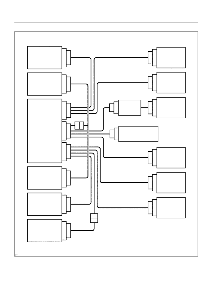
1.
SRS CONNECTORS
Seat Belt
Side Airbag
7
8
2526
Pretensioner
Sensor Assy (RH)
(RH)
Front Seat
Airbag Front
23 24
Airbag Assy
5
6
RH Sensor
(RH) (Squib)
Spiral Cable
Horn Button
1718
19 20
3
4
Sub-Assy
Assy (Squib)
11
12
Airbag Sensor
1
2
Instrument Panel
Assy Center
1516
Junction Block Assy
3
4
Instrument Panel
Passenger
21 22
Airbag
Assy (Squib)
Airbag Sensor
5
6
Front Seat
Front LH
23 24
Airbag Assy
(LH) (Squib)
Side Airbag
7
8
Seat Belt
Sensor Assy (LH)
25 26
Pretensioner
(LH)
13
14
Seat Position
9
10
Airbag Sensor
H42030

60-3
SUPPLEMENTAL RESTRAINT SYSTEM
- SUPPLEMENTAL RESTRAINT SYSTEM
No.
Item
Application
(1)
Terminal Twin-Lock Mechanism
Connectors 2, 4, 6, 8, 10, 11, 12, 13, 14, 15, 17, 21, 22
(2)
Airbag Activation Prevention Mechanism
Connectors 2, 4, 16, 18, 20, 22, 24
(3)
Electrical Connection Check Mechanism
Connectors 1, 2, 3, 4
(4)
Half Connection Prevention Mechanism
Connectors 6, 8, 12, 21
(5)
Connector Lock Mechanism
Connectors 17, 19, 23
(a) All connectors in the SRS are colored in yellow to distin-
guish them from other connectors. Connectors having
special functions and specifically designed for the SRS
are used in the locations shown on the previous page to
ensure high reliability. These connectors use durable
gold-plated terminals.
(1)
Terminal twin-lock mechanism:
Spacer
Each connector has a two-piece component con-
sisting of a housing and a spacer. This design en-
Housing
ables the terminal to be locked securely by two lock-
ing devices (the retainer and the lance) to prevent
terminals from coming out.
(2)
Airbag activation prevention mechanism:
Each connector contains a short spring plate. When
Female
Male
Z05953
the connector is disconnected, the short spring
plate automatically connects positive (+) terminal
and negative (-) terminal of the squib.
When Connector is Connected
When Connector is Disconnected
Short Spring Plate
Short Spring Plate
Housing
Contacting Male Terminal
Housing
Short Spring Plate ON
Terminal
Squib
Squib
Connectors Short Spring Plate
Closed Circuit
R10587

60-4
SUPPLEMENTAL RESTRAINT SYSTEM
- SUPPLEMENTAL RESTRAINT SYSTEM
HINT:
The type of connector is shown in the diagram on the previous
page.
(3)
Electrical connection check mechanism:
This mechanism electrically checks that connectors
are connected correctly and completely. The electri-
cal connection check mechanism is designed so
Disconnection
Detection
that the disconnection detection pin connects with
Pin
the diagnosis terminals when the connector hous-
ing lock is locked.
Airbag Sensor Assy Center
H41646
FHalf Connection
FComplete Connection
Terminal for Diagnosis
Terminal for
Diagnosis
Disconnection Detection Pin
H01315
HINT:
The connectors shown in this illustration are connectors, ”1”,
”2”, ”3” and ”4” in step 1.
(4)
Half connection prevention mechanism:
If the connector is not completely connected, the
connector is disconnected due to the spring opera-
tion to the extent that no continuity exists.
Spring
Stopper
Slider
Stopper
Locking Arm
Locking Part
Rebounded by Slider
(Spring)
C51019
H40180