Toyota Corolla (2004+). Manual - part 107

60-5
SUPPLEMENTAL RESTRAINT SYSTEM
- SUPPLEMENTAL RESTRAINT SYSTEM
(5)
Connector lock mechanism:
Locking the connector lock button securely con-
nects the connector.
H40181
(b) When the vehicle is involved in a frontal collision in the
hatched area (Fig. 1) and the shock is larger than the pre-
determined level, the SRS is activated automatically. A
safing sensor is designed to go on at a smaller decelera-
tion rate than the airbag sensor. As illustrated in Fig. 2,
ignition is caused when current flows to the squib, which
happens when a safing sensor and the deceleration sen-
Fig.1
sor go on simultaneously. When a deceleration force acts
on the sensors, 2 squibs in the driver airbag and front pas-
Power Source
senger airbag ignite and generate gas. The gas discharg-
ing into the driver airbag and front passenger airbag rap-
idly increases the pressure inside the bags, breaking
open the horn button assy and instrument panel. Bag
Safing
Sensor
inflation then ends, and the bags deflate as the gas is dis-
Squibs
charged through discharge holes at the bag’s rear or side.
Fig.2
Deceleration
Sensor
Z14034

60-6
SUPPLEMENTAL RESTRAINT SYSTEM
- SUPPLEMENTAL RESTRAINT SYSTEM
2.
DISCONNECTION OF CONNECTOR FRONT SEAT AIRBAG ASSY
(a) Place a finger on the slider.
(b) Slide the slider to release lock.
(c)
Disconnect the connector.
Slider
Slider
Disconnection is completed
H01584
3.
CONNECTION OF CONNECTOR FOR FRONT SEAT AIRBAG ASSY
(a) Align a lock part of male connector and a slider of female connector in the same direction as shown
in the illustration, fit in them without rubbing.
(b) Be sure to insert until they are locked. After fitting in, pull them slightly to check that they are locked.
(When locked, make sure that the outer returns to its original position and sound at the time of fitting
in can be heard.)
HINT:
_
As the slider slides, do not touch it.
_
Be careful not to deform the release board. If the release board is deformed, replace it with a new one.
Slider
Slider
H01585

60-7
SUPPLEMENTAL RESTRAINT SYSTEM
- SUPPLEMENTAL RESTRAINT SYSTEM
4.
DISCONNECTION OF AIRBAG FRONT SENSOR AND
Outer
SIDE AIRBAG SENSOR
(a) While holding both flank sides of the outer, slide the outer
in the direction shown by an arrow.
(b) Release the lock of the connectors, then disconnect the
connectors.
HINT:
Be sure to hold both flank sides of the outer. If holding the top
H02763
and bottom sides, it will obstruct disconnection.
Lock of connector is released
Disconnection is completed
H02764
5.
CONNECTION OF CONNECTORS FOR AIRBAG FRONT SENSOR AND SIDE AIRBAG SENSOR
(a) Align the male connector (on the side of sensor) with female connector in the same direction as shown
in the illustration and fit them in without rubbing.
(b) As they are fitted in, the outer slides rearward. Press it until the outer returns to its original position
again.
If fitting stops half way, connectors will separate.
(c)
Be sure to insert until they are locked. After fitting in, pull them slightly to check that they are locked.
(When locked, make sure that the outer returns to its original position and sound at the time of fitting
in can be heard.)
HINT:
_
Do not fit in while holding the outer.
_
When fitting in, the outer slides. Do not touch it.
Outer
Outer
Connection is completed
H02768

60-45
SUPPLEMENTAL RESTRAINT SYSTEM
- SEAT POSITION AIR BAG SENSOR
SEAT POSITION AIR BAG SENSOR
60080-02
COMPONENTS
Seat Track Upper Rail Cover RH
Front Seat Assy LH
47.1 (480, 35)
Seat Track Upper Rail Cover LH
Seat Position Airbag Sensor
8.0 (82, 71 in. lbf)
Nm (kgfcm, ftlbf)
: Specified torque
H42055

60-46
SUPPLEMENTAL RESTRAINT SYSTEM
- SEAT POSITION AIR BAG SENSOR
60081-04
REPLACEMENT
HINT:
COMPONENTS: See page 60-45
1.
PRECAUTION (See page 60-1)
2.
DISCONNECT BATTERY NEGATIVE TERMINAL (See page 60-1)
3.
REMOVE SEAT TRACK UPPER RAIL COVER RH
4.
REMOVE SEAT TRACK UPPER RAIL COVER LH
5.
REMOVE FRONT SEAT ASSY LH (See page 72-2)
6.
REMOVE SEAT POSITION AIR BAG SENSOR
(a) Disconnect the connector of the seat position airbag sen-
sor.
(b) Using a torx socket wrench (T30), remove the torx screw
and seat position airbag sensor.
H41697
7.
INSTALL SEAT POSITION AIR BAG SENSOR
(a) Using a torx socket wrench (T30), install the seat position airbag sensor with the torx screw.
Torque: 8.0 N m (82 kgf cm, 71 in. lbf)
(b) Connect the connector of the seat position airbag sensor.
NOTICE:
F
Installation of the connector is done with the seat position airbag sensor installed. Make sure
the seat position airbag sensor is installed to the specified torque.
F
If the seat position airbag sensor has been dropped, or there are cracks, dents or other defects
in the case, bracket or connector, replace the seat position airbag sensor with a new one.
F
When installing the seat position airbag sensor, take care that the SRS wiring does not interfere
with other parts and is not pinched between other parts.
F
After installation, shake the seat position airbag sensor to check that there is no looseness.
8.
INSTALL FRONT SEAT ASSY LH
Torque: 47.1 N m (480 kgf cm, 35 ft lbf)
9.
INSPECT SRS WARNING LIGHT (See page 05-424)

60-43
SUPPLEMENTAL RESTRAINT SYSTEM
- SIDE AIR BAG SENSOR ASSY RH
SIDE AIR BAG SENSOR ASSY RH
6007W-02
COMPONENTS
Side Airbag Sensor Assy RH
8.0 (82, 71 in. lbf)
Front Seat Outer Belt Assy RH
4.9 (50, 43 in. lbf)
Center Pillar Garnish Lower RH
41.2 (420, 30)
Front Door Opening Trim
Weatherstrip RH
Rear Door Opening Trim
Weatherstrip RH
Rear Door Scuff Plate RH
Front Door Scuff Plate RH
Nm (kgfcm, ftlbf)
: Specified torque
H42121

60-44
SUPPLEMENTAL RESTRAINT SYSTEM
- SIDE AIR BAG SENSOR ASSY RH
6007X-03
REPLACEMENT
HINT:
COMPONENTS: See page 60-43
1.
PRECAUTION (See page 60-1)
2.
DISCONNECT BATTERY NEGATIVE TERMINAL (See page 60-1)
3.
REMOVE FRONT DOOR SCUFF PLATE RH (See page 76-21)
4.
REMOVE REAR DOOR SCUFF PLATE RH (See page 76-21)
5.
REMOVE FRONT DOOR OPENING TRIM RH (See page 76-21)
6.
REMOVE REAR DOOR OPENING TRIM RH (See page 76-21)
7.
REMOVE LAP BELT OUTER ANCHOR COVER (See page 76-21)
8.
REMOVE CENTER PILLAR GARNISH LOWER RH (See page 76-21)
9.
REMOVE FRONT SEAT OUTER BELT ASSY RH (See page 61-7)
10. REMOVE SIDE AIR BAG SENSOR ASSY RH
(a) Disconnect the connector from the side airbag sensor
assy RH.
(b) Remove the 2 nuts and side airbag sensor assy RH.
H42054
11. INSPECT SIDE AIR BAG SENSOR ASSY RH (See page 60-8)
12. INSTALL SIDE AIR BAG SENSOR ASSY RH
(a) Install the 2 nuts and side airbag sensor assy RH.
Torque: 8.0 N m (82 kgf cm, 71 in lbf)
(b) Connect the side airbag sensor connector.
NOTICE:
F
Installation of the connector is done with the sensor assembly installed. Make sure that the sen-
sor assembly is installed to the specified torque.
F
If the sensor assembly has been dropped, or there are cracks, dents or other defects in the
case, bracket or connector, replace the sensor assembly with a new one.
F
When installing the sensor assembly, take care that the SRS wiring does not interfere with other
parts and is not pinched between other parts.
F
After installation, shake the sensor assembly to check that there is no looseness.
13. INSTALL FRONT SEAT OUTER BELT ASSY RH
Torque:
Upper bolt: 4.9 N m (50 kgf cm, 43 in. lbf)
Lower bolt: 41.2 N m (420 kgf cm, 30 ft lbf)
14. INSPECT SRS WARNING LIGHT (See page 05-424)
60-21
SUPPLEMENTAL RESTRAINT SYSTEM
- SPIRAL CABLE SUB-ASSY
SPIRAL CABLE SUB-ASSY
6007H-03
COMPONENTS
(See page 60-12)

60-22
SUPPLEMENTAL RESTRAINT SYSTEM
- SPIRAL CABLE SUB-ASSY
6007I-04
REPLACEMENT
HINT:
COMPONENTS: See page 60-12
1.
PRECAUTION (See page 60-1)
2.
DISCONNECT BATTERY NEGATIVE TERMINAL (See page 60-1)
3.
PLACE FRONT WHEELS FACING STRAIGHT AHEAD
(a) Check that the front wheels are facing straight ahead.
4.
REMOVE HORN BUTTON ASSY (See page 60-13)
5.
REMOVE STEERING WHEEL ASSY (See page 50-8)
SST
09950-50013 (09951-05010, 09952-05010, 09953-05020, 09954-05021)
6.
REMOVE STEERING COLUMN COVER
7.
REMOVE SPIRAL CABLE SUB-ASSY
: Claws
(a) Disconnect the airbag connector and the connector from
the spiral cable sub-assy.
(b) Release the 3 claws and remove the spiral cable sub-
assy.
H42123
8.
INSPECT SPIRAL CABLE SUB-ASSY (See page
60-8)
(a) If the following condition is identified, replace the spiral cable sub-assy with a new one.
Condition:
Scratches or cracks on the connector
Cracks, dents or chipping of the spiral cable sub-assy
9.
PLACE FRONT WHEELS FACING STRAIGHT AHEAD
(a) Check that the front wheels are facing straight ahead.
10. INSTALL SPIRAL CABLE SUB-ASSY
(a) Set the turn signal switch in neutral position.
NOTICE:
Make sure of the neutral position since the pin of the turn signal switch may be snapped.
(b) Engage the 3 claws and install the spiral cable sub-assy.
NOTICE:
When replacing the spiral cable sub-assy with a new one, remove the lock pin before installing the
handle.
(c)
Connect the airbag connector and the connector connecting to the spiral cable sub-assy.
(d) Install the steering column cover with the 3 screws.

60-23
SUPPLEMENTAL RESTRAINT SYSTEM
- SPIRAL CABLE SUB-ASSY
11. CENTER SPIRAL CABLE
(a) Check that the ignition switch is turned to OFF.
(b) Check that the battery negative terminal is disconnected.
NOTICE:
Do not start the operation for 90 seconds after removing
the terminal.
(c)
Turn the cable counterclockwise by hand until it becomes
harder to turn.
HINT:
The cable will rotate about 2.5 turns to either left or right of the
center.
H41415
(d) Then rotate the cable clockwise about 2.5 turns to align
the marks.
Matchmarks
H41416
12. INSTALL STEERING WHEEL ASSY (See page 50-8)
Torque: 50 N m (510 kgf cm, 37 ft lbf)
13. INSTALL HORN BUTTON ASSY (See page 60-13)
Torque: 8.8 N m (90 kgf cm, 78 in. lbf)
14. INSPECT HORN BUTTON ASSY (See page 60-8)
15. INSPECT SRS WARNING LIGHT (See page 05-424)

61-6
SEAT BELT
- FRONT SEAT BELT
61084-02
COMPONENTS
Rear Door Opening
Trim RH
Front Door Opening Trim RH
Front Door Scuff Plate RH
Rear Door Scuff
Plate RH
41.2 (420, 30)
Front Shoulder Belt
Anchor Adjuster Assy
Shoulder Anchor Cover
41.2 (420, 30)
Center Pillar Garnish RH
Front Seat Outer Belt Assy RH
Center
Pillar
Garnish
Lower RH
4.9 (50, 43 in.lbf)
Floor
47 (480, 35)
Anchor
Cover
Front Seat Inner
Belt Assy RH
41.2 (420, 30)
41.2 (420, 30)
Nm (kgfcm ftlbf)
: Specified torque
B59290

61-9
SEAT BELT
- FRONT SEAT BELT
6108A-02
DISPOSAL
HINT:
When scrapping vehicles epuipped with a seat belt pretensioner or disposing of a front seat outer belt (with
seat belt pretensioner) always first active the seat belt pretensioner in accordance with the procedure de-
scribed below. If any abnormality occurs in the seat belt pretensioner operation, contact the SERVICE DEPT.
of the TOYOTA MOTOR SALES, U.S.A., INC. When disposing of a front seat outer belt (with seat belt preten-
sioner) activated in a collision, follow the same procedure givenin step 1-(e) in ”DISPOSAL”.
CAUTION:
F
Never dispose of front seat outer belt which has an in-
activated pretensioner.
F
The seat belt pretensioner produces a sizeable ex-
SST
ploding sound when it activates, so perform the op-
eration out-of-door and where it will not create a nui-
sance to nearby residents.
F
When activating a front seat outer belt (with seat belt
B50515
pretensioner), perform the operation at least 10 m (33
ft) away from the front seat outer belt.
F
Use gloves and safety glasses when handling a front
seat belt with activated pretensioner.
F
Always wash your hands with water after completing
the operation.
F
Do not apply water, etc. to a front seat outer belt with
activated pretensioner.
F
When activating the seat belt pretensioner, always
use the specified SST. (SRS Airbag Deployment Tool)
Perform the operation in a place away from electrical
noise.
SST
09082-00700
1.
DISPOSE OF FRONT SEAT OUTER BELT ASSY RH
(WHEN INSTALLED WITH VEHICLE)
HINT:
Check that the battery positive voltage is above 12 V.
B50511

61-10
SEAT BELT
- FRONT SEAT BELT
(a) Check the functioning of SST.
CAUTION:
When activating the seat belt pretensioner, always use a
specified SST.
SST
SST
09082-00700, 09082-00770
B50515
(1)
Connect the SST to the battery.
Connect the red clip of the SST to the battery posi-
tive (+) terminal and the black clip to the battery neg-
ative (-) terminal.
Battery
HINT:
Do not connect the yellow connector which will be connected
SST
to the seat belt pretensioner.
B50511
(2)
Check the functioning of SST.
Press the SST activation switch, and check that the
SST
LED of the SST activation switch lights up.
CAUTION:
If the LED lights up when the activation switch is not
pressed, the SST probably malfunctions, so definitely do
not use the SST.
B50514
(b)
Disconnect the SST from the battery.
(c)
Disconnect the pretensioner connector.
(1)
Disconnect the battery negative terminal.
(2)
Check the SRS airbag system (See page 60-1).
(3)
Remove the front door scuff plate RH (See page 76-21).
(4)
Remove the rear door scuff plate RH (See page 76-21).
(5)
Remove the front door opening trim RH.
(6)
Remove the rear door opening trim RH.
(7)
Remove center pillar garnish lower RH (See page 76-21).
(8)
Disconnect the pretensioner connector as shown in
the illustration.
(d) Install the SST.
(1)
Install the floor anchor of the seat belt.
B50195
B57295
61-11
SEAT BELT
- FRONT SEAT BELT
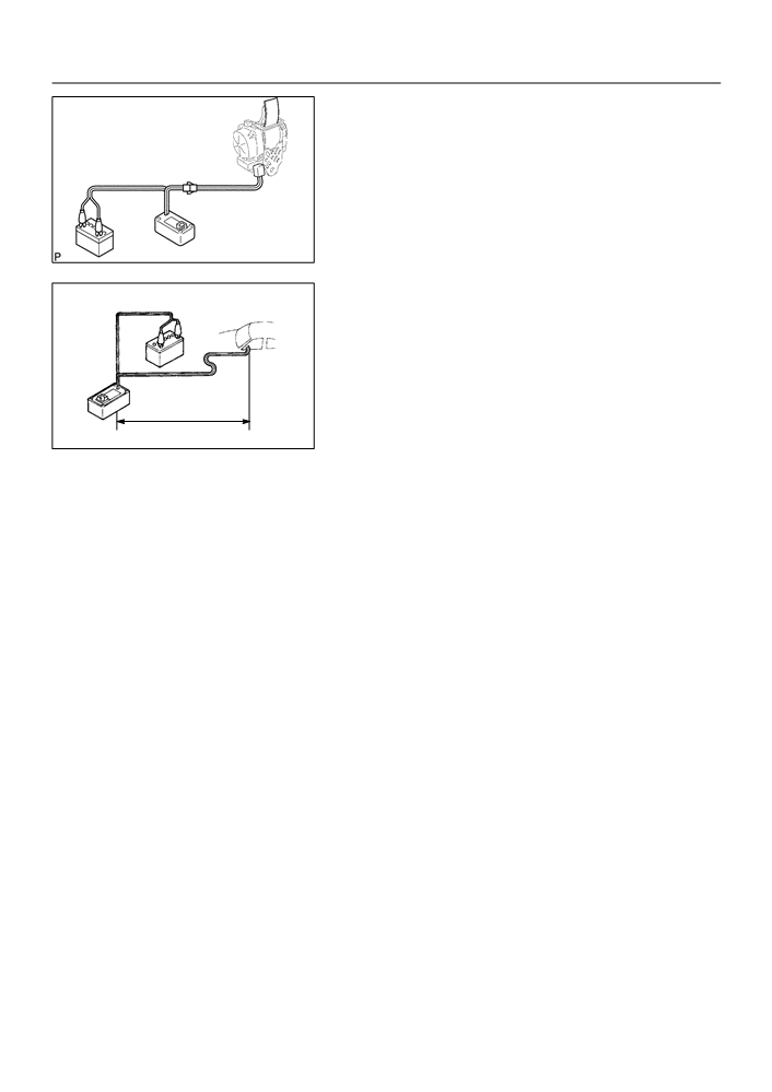
(2)
Connect the 2 SSTs, then connect them to the seat
belt pretensioner.
SST
09082-00700, 09082-00770
NOTICE:
To avoid damaging the SST connector and wire harness,
do not lock the secondary lock of the twin lock.
SST
SST
B51763
(3)
Move the SST at least 10 m (33 ft) away from the
front of the vehicle.
(4)
Close all the doors and windows of the vehicle.
NOTICE:
Take care not to damage the SST wire harness.
(5)
Connect the SST red clip to the battery positive (+)
terminal and the black clip to the negative (-) termi-
10 m (33 ft) or more
nal.
B50513
(e) Activate the seat belt pretensioner.
(1)
Confirm that no one is inside the vehicle or within 10 m (33 ft) area around the vehicle.
(2)
Press the SST activation switch and activate the seat belt pretensioner.
HINT:
The seat belt pretensioner operates simultaneously with the LED of the SST activation switch lighting up.
(f)
Dispose of the front seat outer belt (with seat belt pretensioner).
CAUTION:
F
The rear outer belt is very hot when the seat belt pretensioner is activated, so leave it alone for
at least 30 minutes after activation.
F
Use gloves and safety glasses when handling a front seat outer belt with activated seat belt pre-
tensioner.
F
Always wash your hands with water after completing the operation.
F
Do not apply water, etc. to a front seat outer belt with activated seat belt pretensioner.
HINT:
When scrapping a vehicle, activate the seat belt pretensioner and scrap the vehicle with activated front seat
outer belt being installed.
2.
DISPOSE OF FRONT SEAT OUTER BELT ASSY RH (WHEN NOT INSTALLED WITH VEHICLE)
NOTICE:
F
When disposing of a front seat outer belt (with seat belt pretensioner) only, never use the cus-
tomer’s vehicle to activate the seat belt pretensioner.
F
Be sure to follow the procedure given on the next page when activating the seat belt pretension-
er.
(a) Remove the front seat outer belt asembly (See page 61-7).
HINT:
Cut the belt near the seat belt retractor.

61-12
SEAT BELT
- FRONT SEAT BELT
(b) Check the functioning of SST (See step 1-(a)).
SST
09082-00700, 09082-00770
Battery
SST
B50511
(c)
Install the SST.
(1)
Connect the 2 SSTs, then connect them to the seat
belt pretensioner.
SST
09082-00700, 09082-00770
NOTICE:
To avoid damaging the SST connector and wire harness,
SST
SST
do not lock the secondary lock of the twin lock.
B51763
(2)
Place the front seat outer belt on the ground and
cover it with the disc wheel with tire.
NOTICE:
Place the front seat outer belt, as shown in the illustration.
(3)
Move the SST at least 10 m (33 ft) away from the
disc wheel.
NOTICE:
SST
SST
Take care not to damage the SST wire harness.
B50509
(d) Activate the seat belt pretensioner.
(1)
Connect the SST red clip to the battery positive (+)
terminal and black clip to the battery negative (-)
terminal.
(2)
Check that no one is within 10 m (33 ft) area around
the disc wheel.
10 m (33 ft) or more
(3)
Press the SST activation switch and activate the
seat belt pretensioner.
B50541
HINT:
The seat belt pretensioner operates simultaneously with the
LED of the SST activation switch lighting up.