Toyota Corolla (2004+). Manual - part 105

60-32
SUPPLEMENTAL RESTRAINT SYSTEM
- FRONT SEAT AIRBAG ASSY RH
FRONT SEAT AIRBAG ASSY RH
6007P-03
DISPOSAL
HINT:
F
When scrapping vehicles equipped with an SRS or disposing of the front seat airbag assy always first
deploy the airbag in accordance with the procedure described below. If any abnormality occurs with
the airbag deployment, contact the SERVICE DEPT. of TOYOTA MOTOR SALES, U.S.A., INC.
F
When disposing of a front seat airbag assy with an airbag deployed in a collision, follow the same pro-
cedure given in step 1-(e) in ”DISPOSAL”.
CAUTION:
F
Never dispose of a front seat airbag assy which has
an undeployed airbag.
F
The airbag produces a sizeable exploding sound
when it deploys, so perform the operation out of
doors and where it will not create a nuisance to
nearby residents.
F
When deploying the airbag, always use the specified
SST (SRS Airbag Deployment Tool), perform the
operation in a place away from electrical noise.
F
When deploying an airbag, perform the operation at
SST
least 10 m (33 ft) away from the airbag assy.
F
The front seat airbag assy is very hot when the airbag
is deployed, so leave it alone for at least 30 minutes
after deployment.
H40004
F
Use gloves and safety glasses when handling front
seat airbag assy with the deployed airbag.
F
Always wash your hands with water after completing
the operation.
F
Do not apply water, etc. to a front seat airbag assy
with the deployed airbag.
1.
DISPOSE FRONT SEAT AIRBAG ASSY RH (WHEN
SCRAPPING VEHICLE DEPLOYMENT METHOD)
HINT:
Battery
Prepare a battery for the power source to deploy the airbag.
(a) Check the function of SST (See step 1-(a) on page
60-14).
SST
H40005

60-33
SUPPLEMENTAL RESTRAINT SYSTEM
- FRONT SEAT AIRBAG ASSY RH
(b) Disconnect the front seat airbag assy connector.
NOTICE:
When handling the airbag connector, take care not to
damage the airbag wire harness.
H41647
(c)
Set SST.
(1)
Connect the connectors of the 2 SST to the front
Battery
seat airbag assy connector.
SST
09082-00700, 09082-00750
NOTICE:
To avoid damaging the SST connector and wire harness,
do not lock the secondary lock of the twin lock.
SST
H41648
(2)
Move the SST at least 10 m (33 ft) away from the
front of the vehicle.
(3)
Close all the doors and windows of the vehicle.
NOTICE:
Take care not to damage the SST wire harness.
(4)
Connect the SST red clip to the battery positive (+)
terminal and the black clip to the battery negative
10 m (33 ft) or more
(-) terminal.
H40007
(d) Deploy the airbag.
(1)
Check that no one is inside the vehicle or within 10
m (33 ft) area around the vehicle.
(2)
Press the SST activation switch and deploy the air-
bag.
HINT:
The airbag deploys simultaneously when the LED of SST ac-
tivation switch lights up.
(e) Dispose of the front seat airbag assy.
CAUTION:
F
The front seat airbag assy is very hot when the airbag
is deployed, so l eave it for at least 30 minutes after de-
ployment.
F
Use gloves and safety glasses when handling a front
seat airbag assy with the deployed airbag.
F
Do not apply water, etc. to a front seat airbag assy
with the deployed airbag.
F
Always wash your hands with water after completing
the operation.
HINT:
When scrapping a vehicle, deploy the airbag and scrap the ve-
hicle with the front seat airbag assy being installed.

60-34
SUPPLEMENTAL RESTRAINT SYSTEM
- FRONT SEAT AIRBAG ASSY RH
2.
DISPOSE FRONT SEAT AIRBAG ASSY RH (WHEN
DISPOSING OF AIRBAG ASSEMBLY DEPLOYMENT
METHOD)
NOTICE:
F
When disposing of the front seat airbag assy only,
never use the customer’s vehicle to deploy the air-
bag.
F
Be sure to follow the procedure given below when de-
ploying the airbag.
HINT:
Prepare a battery for the power source to deploy the airbag.
(a) Remove the front seat airbag assy.
(1)
Remove the 2 nuts and front seat airbag assy from
the seatback assembly.
CAUTION:
Store the front seat airbag assy with the airbag deployment
side facing upward.
(b) Using a service-purpose wire harness, tie down the front
seat airbag assy.
Wire Harness
Wire harness: Stripped wire harness section
Diameter
1.25 mm 2 or more (0.0019 in 2 or more)
CAUTION:
If the wire harness is too thin or some other things are used
to tie down the front seat airbag assy, it may be snapped by
Stripped Wire Harness Section
the shock when the airbag is deployed. This is highly dan-
H40008
gerous. Be sure to use of wire harness which is at least 1.25
mm 2 (0.0019 in 2).
HINT:
To calculate the area of the stripped wire harness section :
Area = 3.14 x (Diameter) 2 divided by 4
(1)
Install the 2 nuts in the front seat airbag assy.
H41437

60-35
SUPPLEMENTAL RESTRAINT SYSTEM
- FRONT SEAT AIRBAG ASSY RH
(2)
Wind the wire harness around the stud bolts of the
front seat airbag assy as shown in the illustration.
H41438
(3)
Position the front seat airbag assy inside the tire
with the airbag deployment direction facing inside.
Tire size : Must exceed the following dimensions:-
Width 185 mm (7.28 in.)
Inner diameter 360 mm (14.17 in.)
CAUTION:
F
Make sure the wire harness is tight. It is very danger-
ous when loosened wire harness results in the front
H40526
seat airbag assy coming free due to the shock from
the airbag deployment.
F
Always tie down the front seat airbag assy with the
airbag facing inside.
NOTICE:
The tire will be marked by the airbag deployment, so use
the redundant tire.
(c)
Check the function of SST (See step 1-(a) on page
60-14)
SST
09082-00700
Battery
SST
H40005
(d) Place the tires.
(1)
Place at least 2 tires under the tire to which the front
seat airbag assy is tied.
(2)
Place at least 2 tires over the tire to which the front
Tires
seat airbag assy is tied. The top tire should have the
(5 or More)
wheel installed.
H01336

60-36
SUPPLEMENTAL RESTRAINT SYSTEM
- FRONT SEAT AIRBAG ASSY RH
(3)
Tie the tires together with 2 wire harnesses.
CAUTION:
Make sure that the wire harnesses are tight. It is very dan-
gerous when loosened wire harnesses results in the tires
coming free due to the shock from the airbag deploying.
HINT:
Place the SST connector and wire harness inside tires. Secure
at least 1 m (3 ft) of slack for the wire harness.
H40016
(e) Set SST.
Front Seat
Connect the connector of the 2 SST to the front seat air-
Airbag Assy
bag assy connector.
SST
09082-00700, 09082-00750
Battery
NOTICE:
SST
To avoid damaging the SST connector and wire harness,
do not lock the secondary lock of the twin lock.
(f)
Deploy the airbag.
10 m (33ft) or more
H01337
(1)
Connect the SST red clip to the battery positive (+)
terminal and the black clip to the battery negative
(-) terminal.
(2)
Check that no one is within 10 m (33 ft) radius
around the tire which the front seat airbag assy is
tied to.
(3)
Press the SST activation switch and deploy the air-
bag.
HINT:
The airbag deploys simultaneously when the LED of the SST
activation switch lights up.
(g) Dispose of the front seat airbag assy.
CAUTION:
F
The front seat airbag assy is very hot when the airbag
is deployed, so l eave it for at least 30 minutes after de-
ployment.
F
Use gloves and safety glasses when handling a front
seat airbag assy with the deployed airbag.
F
Do not apply water etc. to a front seat airbag assy with
H00544
the deployed airbag.
F
Always wash your hands with water after completing
the operation.
(1)
Remove the front seat airbag assy from the tire.
(2)
Place the front seat airbag assy in a vinyl bag, tie the
end tightly and dispose of it in the same way as oth-
er general parts disposal.

60-12
SUPPLEMENTAL RESTRAINT SYSTEM
- HORN BUTTON ASSY (April, 2003)
HORN BUTTON ASSY (April, 2003)
6007E-03
COMPONENTS
8.8 (90, 78 in. lbf)
Steering Column UPR Cover
Spiral Cable
Sub-Assy
50 (510, 37)
Steering Wheel Assy
Horn Button Assy
Steering Column LWR Cover
8.8 (90, 78 in. lbf)
Nm (kgfcm, ftlbf)
: Specified torque
H41974

60-14
SUPPLEMENTAL RESTRAINT SYSTEM
- HORN BUTTON ASSY (April, 2003)
600BZ-03
DISPOSAL
HINT:
When scrapping vehicle equipped with an SRS or disposing of a horn button assy, always first deploy the
airbag in accordance with the procedure described below. If any abnormality occurs in the airbag deploy-
ment, contact the SERVICE DEPT. of TOYOTA MOTOR SALES, U.S.A., INC.
CAUTION:
F
Never dispose of a horn button assy which has an un-
deployed airbag.
F
The airbag produces a sizeable exploding sound
when it deploys, so perform the operation out of
doors and the place where it will not create a nuisance
to nearby residents.
F
When deploying the airbag, always use the specified
SST (SRS Airbag Deployment Tool). Perform the op-
eration in a place away from electrical noise.
F
When deploying an airbag, perform the operation at
SST
least 10 m (33 ft) away from the horn button assy.
F
The horn button assy is very hot when the airbag is
deployed, so leave it for at least 30 minutes after de-
ployment.
H40004
F
Use gloves and safety glasses when handling a horn
button assy with the deployed airbag.
F
Always wash your hands with water after completing
the operation.
F
Do not apply water, etc. to a horn button assy at-
tached on the deployed airbag.
1.
DISPOSE OF HORN BUTTON ASSY
(WHEN
SCRAPPING VEHICLE DEPLOYMENT METHOD)
Battery
HINT:
Prepare a battery for the power source to deploy the airbag.
SST
H40005
(a) Check the function of SST.
CAUTION:
When deploying the airbag, always use the specified SST:
SRS Airbag Deployment Tool.
SST
SST
09082-00700
H40004

60-15
SUPPLEMENTAL RESTRAINT SYSTEM
- HORN BUTTON ASSY (April, 2003)
(1)
Connect the SST to the battery.
Connect the red clip of the SST to the battery posi-
tive (+) terminal and the black clip to the battery neg-
Battery
ative (-) terminal.
HINT:
Do not connect the yellow connector which will be connected
SST
with the supplemental restraint system.
H40005
(2)
Check the function of SST.
Press the SST activation switch, and check that the
LED of the SST activation switch lights up.
SST
CAUTION:
If the LED lights up when the activation switch is not being
pressed, SST malfunction is probable, so definitely do not
use the SST.
(3)
Disconnect the SST from the battery.
H40006
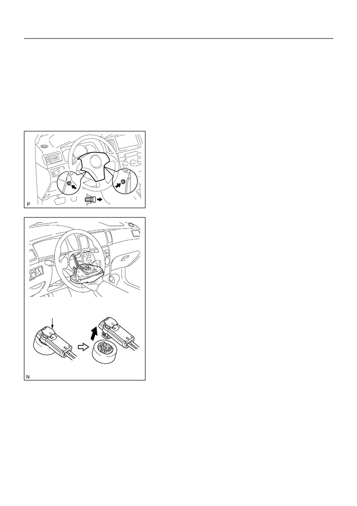
(b) Set SST.
CAUTION:
Check that there is no looseness in the steering wheel and
horn button assy.
(1)
While turning the steering wheel to the right / left, re-
move the 3 screws and column lower cover.
(2)
Disconnect the airbag connector of the spiral cable.
H42033
(3)
Connect the connectors of the 2 SST to the airbag
connector of the spiral cable back side.
SST
09082-00700, 09082-00780
SST
H42034
(4)
Move the SST at least 10 m (33 ft) away from the
front of the vehicle.
(5)
Close all the doors and windows of the vehicle.
Battery
NOTICE:
Take care not to damage the SST wire harness.
(6)
Connect the red clip of the SST to the battery posi-
SST
tive (+) terminal and the black clip to the negative (-)
10 m (33 ft) or more
terminal.
H40007

60-16
SUPPLEMENTAL RESTRAINT SYSTEM
- HORN BUTTON ASSY (April, 2003)
(c)
Deploy the airbag.
(1)
Confirm that no one is inside the vehicle or within 10
m (33 ft) area around the vehicle.
(2)
Press the SST activation switch and deploy the air-
bag.
HINT:
The airbag deploys simultaneously when the LED of the SST
activation switch lights up.
(d) Dispose of the horn button assy (with airbag).
CAUTION:
F
The horn button assy is very hot when the airbag is
deployed, so leave it for at least 30 minutes after de-
ployment.
F
When moving a vehicle which has a horn button assy
with deployed airbag for scrapping, use gloves and
safety glasses.
F
Use gloves and safety glasses when handling a horn
button assy with the deployed airbag.
F
Always wash your hands with water after completing
the operation.
F
Do not apply water, etc. to a horn button assy at-
tached on the deployed airbag.
HINT:
When scrapping a vehicle, deploy the airbag and scrap the ve-
hicle with the horn button assy still installed.
2.
DISPOSE OF HORN BUTTON ASSY
(WHEN
DISPOSING OF AIRBAG ASSEMBLY DEPLOYMENT
METHOD)
NOTICE:
F
When disposing of the horn button assy (with airbag)
only, never use the customers vehicle to deploy the
airbag.
F
Be sure to follow the procedure given below when de-
ploying the airbag.
HINT:
Prepare a battery for the power source to deploy the airbag.
(a) Remove the horn button assy (See page 60-13).
CAUTION:
When storing the horn button assy, keep the upper surface
of the pad facing upward.
(b) Using a service-purpose wire harness, tie down the horn
button assy to the disc wheel.
Wire Harness
Wire harness: Stripped wire harness section
Diameter
1.25 mm 2 or more (0.0019 in 2. or more)
CAUTION:
If the wire harness is too thin or some other things are used
to tie down the horn button assy, it may be snapped by the
Stripped Wire Harness Section
shock when the airbag is deployed. This is highly danger-
H40008
ous. Be sure to use the wire harness which is at least 1.25
mm 2 (0.0019 in 2).

60-17
SUPPLEMENTAL RESTRAINT SYSTEM
- HORN BUTTON ASSY (April, 2003)
HINT:
To calculate the area of the stripped wire harness section:
Area = 3.14 x (Diameter) 2 divided by 4
(1)
Install the 2 bolts with washers in the 2 bolt holes in
the horn button assy.
Bolt:
L: 35.0 mm (1.387 in.)
M: 6.0 mm (0.236 in.)
L
Pitch: 1.0 mm (0.039 in.)
NOTICE:
M
F
Tighten the bolts by hand until the bolts become diffi-
H42035
cult to turn.
F
Do not tighten the bolts too much.
(2)
Connect the connectors of the SST to the horn but-
ton assy connectors.
SST
09082-00802 (09082-10801, 09082-30801)
H42036
(3)
Using 3 wire harness, wind the wire harness at least
twice each around the bolts installed on the left and
right sides of the horn button assy.
CAUTION:
F
Tightly wind the wire harness around the bolts so that
there is no slack.
F
If there is slack in the wire harness, the horn button
assy may come loose due to the shock when the air-
bag is deployed. This is highly dangerous.
Twice or more
H42037

60-18
SUPPLEMENTAL RESTRAINT SYSTEM
- HORN BUTTON ASSY (April, 2003)
(4)
Face the upper surface of the horn button assy up-
ward. Separately tie the left and right sides of the
horn button assy to the disc wheel through the hub
nut holes. Position the horn button assy connector
so that it hangs downward through a hub hole in the
disc wheel.
CAUTION:
F
Make sure that the wire harness is tight. It is very dan-
SST
H42038
gerous when the loosened wire harness results in the
horn button assy coming free through the shock from
the airbag deployment.
F
Always tie down the horn button assy with the pad
side facing upward. It is very dangerous if the horn
button assy is tied down with the metal surface facing
upward as the wire harness will be cut by the shock
from the airbag deployment and the horn button assy
will be flown into the air.
NOTICE:
The disc wheel will be marked by airbag deployment, so
when disposing of the airbag, use a redundant disc wheel.
(c)
Check the function of SST (See step 1-(a)).
Battery
SST
H40005
(d) Set SST.
CAUTION:
Place the disc wheel on the level ground.
SST
(1)
Connect the connector of the SST.
SST
09082-00700
NOTICE:
To avoid damaging the SST connector and wire harness,
do not lock the secondary lock of the twin lock. Also, se-
SST
H42039
cure some slack for the SST wire harness inside the disc
wheel.
(2)
Move the SST at least 10 m (33 ft) away from the
horn button assy tied down on the disc wheel.
Battery
SST
10 m (33 ft) or more
H05075

60-19
SUPPLEMENTAL RESTRAINT SYSTEM
- HORN BUTTON ASSY (April, 2003)
(e) Cover the horn button assy with a cardboard box or tires.
Y
F
Covering method using a cardboard box:
Cover the horn button assy with the cardboard box
Y
and weight the cardboard box down in 4 places with
X
at least 190 N (20 kg, 44 lb).
Size of cardboard box:
Must exceed the following dimensions:
X = 460 mm (18.11 in.)
Weight
H02586
Y = 650 mm (25.59 in.)
NOTICE:
F
When dimension Y of the cardboard box exceeds the
diameter of the disc wheel with tire to which the horn
button assy is tied, X should be the following size.
X = 460 mm (18.11 in.) + width of tire
F
If a cardboard box smaller than the specified size is
used, the cardboard box will be broken by the shock
from the airbag deployment.
Inner Diam.
F
Covering method using tires:
Place at least 3 tires without disc wheel on top of the
Width
disc wheel with tire to which the horn button assy is
Tires
tied.
(3 or More)
Tire size: Must exceed the following dimensions-
Width: 185 mm (7.28 in.)
Inner diameter: 360 mm (14.17 in.)
CAUTION:
H40013
Do not use tires with disc wheels.
NOTICE:
The tires may be marked by the airbag deployment, so use
the redundant tires.
(f)
Deploy the airbag.
(1)
Connect the SST red clip to the battery positive (+)
Battery
terminal and the black clip to the battery negative
(-) terminal.
(2)
Check that no one is within 10 m (33 ft) area around
SST
the disc wheel which the horn button assy is tied to.
(3)
Press the SST activation switch and deploy the air-
10 m (33 ft) or more
bag.
H05075
HINT:
The airbag deploys simultaneously when the LED of the SST
activation switch lights up.

60-20
SUPPLEMENTAL RESTRAINT SYSTEM
- HORN BUTTON ASSY (April, 2003)
(g) Dispose of the horn button assy (with airbag).
CAUTION:
F
The horn button assy is very hot when the airbag is
deployed, so leave it for at least 30 minutes after de-
ployment.
F
Use gloves and safety glasses when handling a horn
button assy with the deployed airbag.
F
Always wash your hands with water after completing
C51699
the operation.
F
Do not apply water, etc. to a horn button assy at-
tached on the deployed airbag.
(1)
Remove the horn button assy from the disc wheel.
(2)
Place the horn button assy in a vinyl bag, tie the end
tightly and dispose of it in the same way as other
general parts disposal.
60-13
SUPPLEMENTAL RESTRAINT SYSTEM
- HORN BUTTON ASSY (April, 2003)
6007F-05
REPLACEMENT
HINT:
COMPONENTS: See page 60-12
1.
PRECAUTION (See page 60-1)
2.
DISCONNECT BATTERY NEGATIVE TERMINAL (See page 60-1)
3.
REMOVE HORN BUTTON ASSY
(a) Place the front wheels facing straight ahead.
(b) Using a torx socket wrench (T30), loosen the 2 torx
screws until the groove along the screw circumference
catches on the screw case.
H42062
(c)
Pull out the horn button assy from the steering wheel
assy.
(d) Using a screwdriver, release the lock part of each airbag
connector and disconnect the 2 airbag connectors.
F42417
4.
INSPECT HORN BUTTON ASSY (See page 60-8)
5.
INSTALL HORN BUTTON ASSY
(a) Connect the airbag connectors and horn connector.
(b) Install the horn button assy after confirming that the circumference groove of the torx screws is caught
on the screw case.
(c)
Using a torx socket wrench (T 30), install the 2 screws.
Torque: 8.8 N m (90 kgf cm, 78 in. lbf)
6.
INSPECT SRS WARNING LIGHT (See page 05-424)

60-8
SUPPLEMENTAL RESTRAINT SYSTEM
- SUPPLEMENTAL RESTRAINT SYSTEM
600BY-02
ON-VEHICLE INSPECTION
1.
HORN BUTTON ASSY (VEHICLES NOT INVOLVED IN
COLLISION)
(a) Check the diagnostic system (See page 05-424).
(b) Visually check the following item with the horn button assy
(with airbag) installed in the vehicle.
Check cuts, minute cracks or marked discoloration on the
horn button assy top surface and in the grooved portion.
H42031
2.
HORN BUTTON ASSY(VEHICLE INVOLVED IN COLLI-
SION AND AIRBAG IS NOT DEPLOYED)
(a) Check the diagnostic system (See page 05-424).
(b) Visually check the following items with the horn button
assy (with airbag) removed from the vehicle.
F
Check cuts, minute cracks or marked discoloration
on the horn button assy top surface and in the
grooved portion.
H42040
F
Check cuts and cracks in wire harness, and chip-
ping in connectors.
F
Check the deformation on the steering wheel.
F
Check the deformation on the horn button contact
plate of the steering wheel assy.
HINT:
F
If the horn button contact plate of the steering wheel assy
is deformed, never repair it. Always replace the horn but-
ton assy with a new one.
H42041
F
There should be no interference between the horn button
assy and steering wheel, and the clearance should be
uniform all the way around when the new horn button
assy is installed on the steering wheel.
CAUTION:
For removal and installation of the horn button assy, see
page 60-13, and be sure to follow the correct procedure.
H42032