Toyota Corolla (2004+). Manual - part 103

55-35
HEATER & AIR CONDITIONER
- COOLER COMPRESSOR ASSY
(b) Using a vise pliers, hold the magnet clutch hub.
(c)
Remove the bolt, magnet clutch hub and magnet clutch
washer.
I32422
(d) Using a snap ring expander, remove the snap ring and
magnet clutch rotor.
(e) Remove the screw, disconnect the connector.
E37091
(f)
Using a snap ring expander, remove the snap ring and
magnet clutch starter.
E50116
8.
REMOVE COOLER COMPRESSOR ASSY
9.
INSTALL MAGNET CLUTCH ASSY
(a) Matching the parts shown in the illustration, install the
magnet clutch starter.
I32460

55-36
HEATER & AIR CONDITIONER
- COOLER COMPRESSOR ASSY
(b) Using a snap ring expander, install a new snap ring with
the chamfered side facing up.
(c)
Install the screw, connect the connector.
I32461
(d) Using a snap ring expander, install the magnet clutch ro-
tor and a new snap ring with the chamfered side facing up.
(e) Install the magnet clutch washer and magnet clutch hub.
NOTICE:
Do not change the combination of the magnet clutch wash-
ers used before disassembly.
I31582
(f)
Using a vise pliers, hold the magnet clutch hub and install
the bolt.
Torque: 18 N m (183 kgf cm, 13 ft lbf)
I32423
10. INSPECT MAGNETIC CLUTCH CLEARANCE
(a) Set the dial indicator to the magnet clutch hub.
(b) Connect the battery positive lead to the terminal 1 of mag-
net clutch connector and the negative lead to the earth
wire. Turn on and off the magnet clutch and measure the
clearance.
Standard clearance:
0.35 - 0.60 mm (0.013 - 0.023 in.)
I32424
If the measured value is out of the standard range, remove the
magnet clutch hub and adjust it with magnet clutch washers.
NOTICE:
Adjustment shall be performed with 3 or less magnet
clutch washers.

55-37
HEATER & AIR CONDITIONER
- COOLER COMPRESSOR ASSY
11. INSPECT COMPRESSOR OIL
(a) When replacing the compressor and magnetic clutch with new one, after gradually removing the refrig-
erant gas from the service valve, drain the following amount of oil from the new compressor and mag-
netic clutch before installation.
Standard:
(Oil capacity inside new compressor and magnetic clutch: 120 + 15 cc (4.0 + 0.5 fl. oz.) ) - (Re-
maining oil amount in the removed compressor and magnetic clutch) = (Oil amount to be re-
moved when replacing)
NOTICE:
F
When checking the compressor oil level, observe the precautions on the cooler removal/instal-
lation.
F
Because compressor oil remains in the pipes of the vehicle, if a new compressor and magnetic
clutch is installed without removing some oil inside, the oil amount becomes too much, pre-
venting heat exchange in the refrigerant cycle and causing refrigerant failure.
F
If the remaining oil in the removed compressor and magnetic clutch is too small in volume,
check for oil leakage.
F
Be sure to use ND-OIL8 for compressor oil.
12. INSTALL COMPRESSOR AND MAGNETIC CLUTCH
(a) Install the compressor and magnetic clutch with the 3
bolts.
(1)
Toque: 29 N m (295 kgf cm, 21 ft lbf)
NOTICE:
(2)
Tighten the bolts in following order shown in the illustra-
tion to install the compressor and magnetic clutch.
(b) Connect the connector.
(3)
I32421
13. INSTALL DISCHARGE HOSE SUB-ASSY
(a) Remove the attached vinyl tape from the hose.
(b) Sufficiently apply compressor oil to the new O-ring and
fit surface of the compressor and magnetic clutch.
Compressor oil: ND-OIL8 or equivalent
(c)
Install a O-ring to the discharge hose sub-assy.
(d) Install the discharge hose sub-assy to the compressor
and magnetic clutch with the bolt.
Torque: 9.8 N m (100 kgf cm, 87 in. lbf)
I32459

55-38
HEATER & AIR CONDITIONER
- COOLER COMPRESSOR ASSY
14. INSTALL COOLER REFRIGERANT SUCTION HOSE
NO.1
(a) Remove the attached vinyl tape from the hose.
(b) Sufficiently apply compressor oil to the new O-ring and
fit surface of the compressor and magnetic clutch.
Compressor oil: ND-OIL8 or equivalent
(c)
Install a O-ring to the cooler refrigerant suction hose No.
1.
(d) Install the cooler refrigerant suction hose No. 1 to the
compressor and magnetic clutch with the bolt.
Torque: 9.8 N m (100 kgf cm, 87 in. lbf)
I32458
15. CHARGE REFRIGERANT (See page 55-11)
SST
07110-58060 (07117-58060, 07117-58070, 07117-58080, 07117-58090, 07117-78050,
07117-88060, 07117-88070, 07117-88080), 07117-48130, 07117-48140
Specified amount: 490
30 g (17.28
1.06 oz.)
16. WARM UP ENGINE
17. INSPECT LEAKAGE OF REFRIGERANT (See page 55-11)
55-13
HEATER & AIR CONDITIONER
- HEATER CONTROL & ACCESSORY ASSY
HEATER CONTROL & ACCESSORY ASSY
550IT-01
REPLACEMENT
1.
REMOVE CONSOLE PANEL UPPER (See page 71-10)
2.
REMOVE INSTRUMENT CLUSTER FINISH PANEL (See page 71-10)
3.
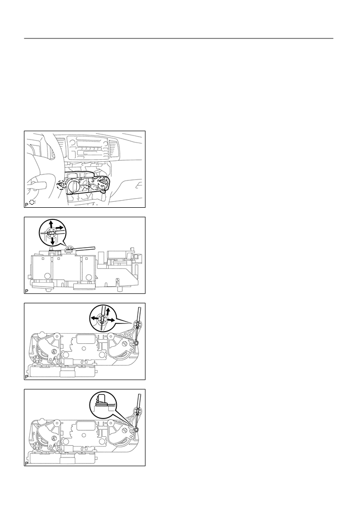
REMOVE HEATER CONTROL & ACCESSORY ASSY
(a) Release the 2 fitting claws and pull out the heater control
& accessory assy.
2 Claws
I32427
(b) Using a screwdriver, open the claw of the cable clamp and
disconnect the defroster damper control cable.
NOTICE:
F
Be careful not to bend the cable wire.
F
If the cable wire bends, the heater control & accesso-
ry assy operationality becomes worse.
HINT:
Tape the screwdriver tip before use.
I32428
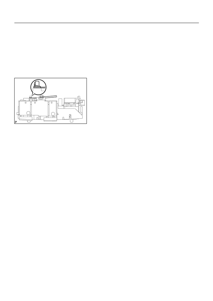
(c)
Using a screwdriver, open the claw of the cable clamp and
disconnect the air mix damper control cable.
NOTICE:
F
Be careful not to bend the cable wire.
F
If the cable wire bends, the heater control & accesso-
ry assy operationality becomes worse.
HINT:
Tape the screwdriver tip before use.
I32429
(d) Disconnect the connector, remove the heater control &
accessory assy.
4.
INSTALL HEATER CONTROL & ACCESSORY ASSY
(a) Install the inner cable end of the air mix damper control
cable to the heater control lever.
(b) Install the outer cable of the air mix damper control cable
to the cable clamp.
NOTICE:
F
Be careful not to bend the cable wire.
F
If the cable wire bends, the heater control & accesso-
I32430
ry assy operationality becomes worse.
55-14
HEATER & AIR CONDITIONER
- HEATER CONTROL & ACCESSORY ASSY
HINT:
F
Operating the heater control knob and check that it prop-
erly stops at both ends of MAX. COOL and MAX. HOT
and no recoil is identified.
F
Check that the outer cable should not be disengaged
(moved) from the heater control & accessory assy when
the cable is pulled.
(c)
Install the inner cable end of the defroster damper control
cable to the heater control lever.
(d) Install the outer cable of the defroster damper control
cable to the cable clamp.
NOTICE:
F
Be careful not to bend the cable wire.
F
If the cable wire bends, the heater control & accesso-
ry assy operationality becomes worse.
I32431
HINT:
F
Operating the heater control knob and check that it prop-
erly stops at both ends of FACE and DEF and no recoil is
identified.
F
Check that the outer cable should not be disengaged
(moved) from the heater control & accessory assy when
the cable is pulled.
(e) Connect the connector, install the heater control & acces-
sory assy.
55-3
HEATER & AIR CONDITIONER
- AIR CONDITIONING SYSTEM
550IP-01
INSPECTION
1.
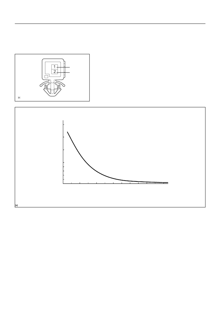
COOLER THERMISTOR NO.1
(a) Check resistance between terminals 1 and 2 of cooler
-
thermistor No. 1 at each temperature, as shown in the
+
chart.
Resistance:
I32480
40
30
Resistance (kW)
20
10
8
6
4
2
0
–30 -20 -10
0
10
30
40
50
60
80
20
70
Temperature (FC)
I30145
If resistance value is not as specified, replace the sensor.
55-4
HEATER & AIR CONDITIONER
- AIR CONDITIONING SYSTEM
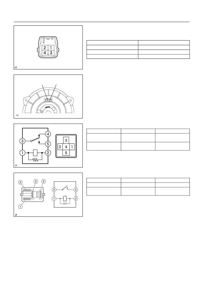
2.
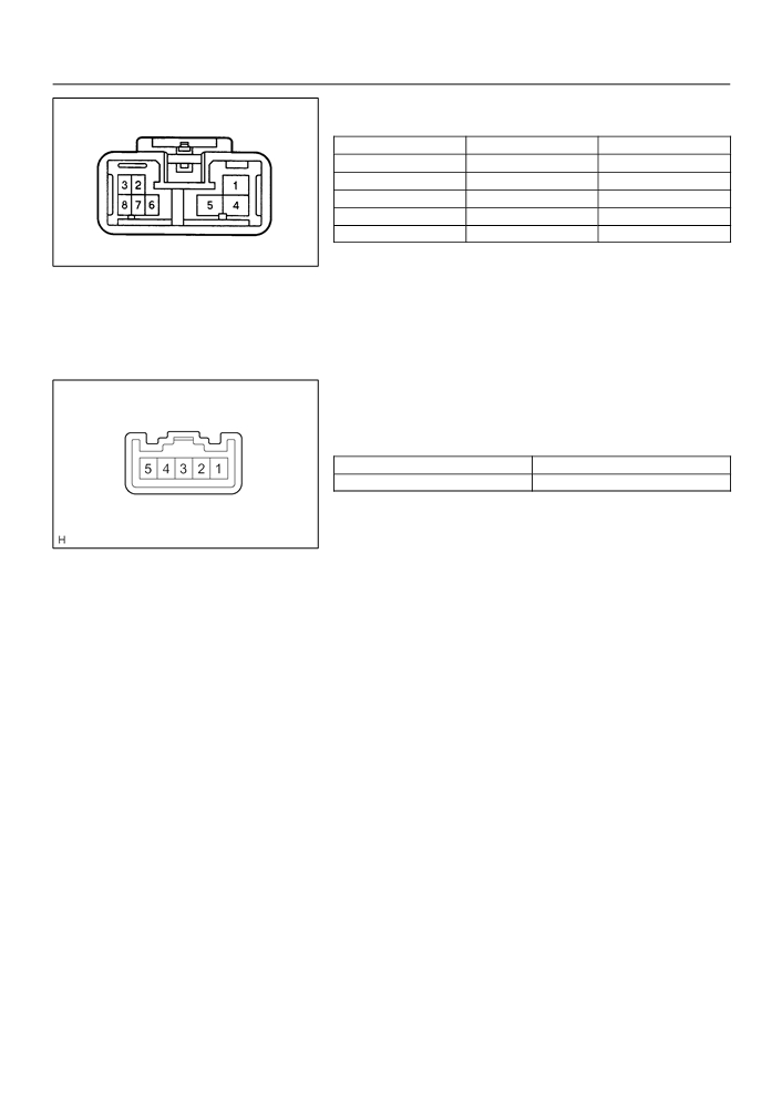
COOLER AND ACCESSORY ASSY
(a) Inspect blower switch continuity.
Condition / Circuit
Tester connection
Specified condition
OFF
-
No continuity
LO
1 - 8
Continuity
M1
1 - 6 - 8
Continuity
M2
1 - 5 - 8
Continuity
HI
1 - 4 - 8
Continuity
E37726
If continuity is not as specified, replace the air conditioner con-
trol assy.
(b) Inspect illumination operation.
Connect the positive (+) lead from the battery to terminal
2 and negative (-) lead to terminal 3 then check that the
illuminations light up.
If there is bulb not light up, replace the bulb.
3.
COOLER SWITCH HOLE COVER
(a) Inspect switch continuity.
Check the continuity between terminals while switch is
pressed, as shown in the chart.
Tester connection
Specified condition
2 - 5
Continuity
If continuity is not as specified, replace the cooler switch.
(b) Inspect illumination operation.
E50533
Connect the positive (+) lead from the battery to terminal
4 and negative (-) lead to terminal 3 then check that the
illuminations light up.
If operation is not as specified, replace the cooler switch.
(c)
Inspect indicator operation.
(1)
Connect the positive (+) lead from the battery to ter-
minal 2 and the negative (-) lead to terminal 1.
(2)
Push the A/C button in and then check that the indi-
cator lights up.
If operation is not as specified, replace the cooler switch.
(d) Inspect dimming operation
(1)
Connect the positive (+) lead from the battery to ter-
minal 2 and the negative (-) lead to terminal 1 while
press the switch.
(2)
Connect the positive (+) lead from battery to termi-
nal 4 and then check that the indicator dims.
If operation is not as specified, replace the cooler switch.
55-5
HEATER & AIR CONDITIONER
- AIR CONDITIONING SYSTEM
4.
BLOWER RESISTOR
(a) Measure resistance between terminals, as shown in the
chart below.
Tester connection
Specified condition
1 - 2
1.398 - 1.605 W
1 - 3
0.465 - 0.535 W
1 - 4
3.069 - 3.531 W
If resistance is not as specified, replace the blower resistor.
E32877
5.
BLOWER W/FAN MOTOR SUB-ASSY
(a) Connect the positive (+) lead from the battery to terminal
2
1
2 and negative (-) to terminal 1, then check that the motor
operation smoothly.
If operation is not as specified, replace the blower motor.
I30151
6.
HEATER BLOWER MOTOR RELAY ASSY
Condition
tester connection
Specified condition
1 - 2
constant
Continuity
3 - 4
Apply B+ between
3 - 5
Continuity
terminals 1 and 2.
If continuity is not as specified, replace the heater blower motor
relay.
E32993
7.
MAGNET-CLUTCH RELAY
Condition
tester connection
Specified condition
constant
1 - 2
Continuity
Apply B+ between
3 - 5
Continuity
terminals 1 and 2.
If continuity is not as specified, replace the magnet-clutch relay.
I30152

55-2
HEATER & AIR CONDITIONER
- AIR CONDITIONING SYSTEM
550IO-01
ON-VEHICLE INSPECTION
1.
INSPECT PRESSURE SWITCH NO.1.
1
(a) Magnetic clutch control:
Inspect pressure switch operation.
(1)
Set on the manifold gauge set.
2
3
(2)
Connect the positive (+) lead from the ohmmeter to
terminal 4 and the negative (-) lead to terminal 1.
4
(3)
Check continuity between terminals when refriger-
Low pressure side
High pressure side
ant pressure is changed, as shown in the illustra-
ON (Continuity)
tion.
If operation is not as specified, replace the pressure switch.
196 kpa
3,140 kpa
(132.0 kgf/cm2 455 psi)
(2.0 kgf/cm2 28 psi)
OFF (No continuity) OFF (No continuity)
I30146
(b) Cooling fan control:
1
Inspect pressure switch operation.
(1)
Connect the positive (+) lead from the ohmmeter to
terminal 2 and the negative (-) lead to terminal 3.
2
3
(2)
Check continuity between terminals when refriger-
ant pressure is changed, as shown in the illustra-
tion.
4
If operation is not as specified, replace the pressure switch.
1,226 kpa
(12.5 kgf/cm2 178 psi)
ON
OFF
(Continuity)
(No continuity)
1,520 kpa
(15.5 kgf/cm2 220 psi)
I30291
2.
COOLER COMPRESSOR ASSY W/MAGNETIC CLUTCH
(a) Connect the positive (+) lead from the battery to terminal and the negative (-) lead to the body ground.
(b) Check that the magnetic clutch energized.
If operation is not as specified, replace the magnet clutch assy.
55-1
HEATER & AIR CONDITIONER
- AIR CONDITIONING SYSTEM
AIR CONDITIONING SYSTEM
550IN-01
PRECAUTION
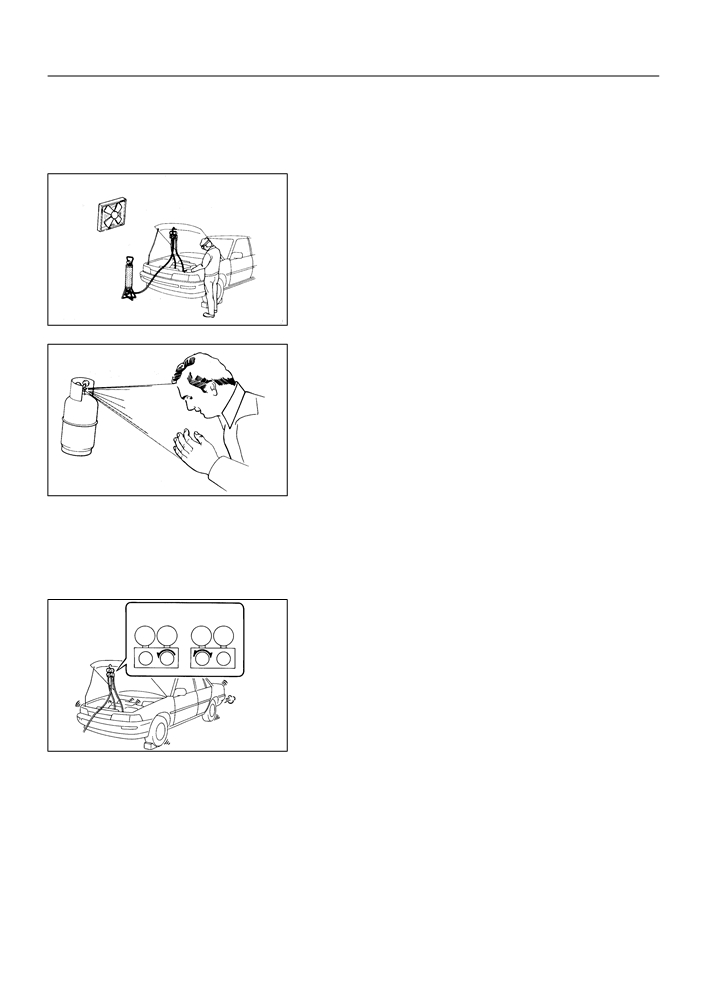
1.
DO NOT HANDLE REFRIGERANT IN AN ENCLOSED
AREA OR NEAR AN OPEN FLAME
2.
ALWAYS WEAR EYE PROTECTION
AC2810
3.
BE CAREFUL NOT TO GET LIQUID REFRIGERANT IN
YOUR EYES OR ON YOUR SKIN
If liquid refrigerant gets in your eyes or on your skin.
(a) Wash the area with lots of cool water.
CAUTION:
Do not rub your eyes or skin.
(b) Apply clean petroleum jelly to the skin.
(c)
Go immediately to a physician or hospital for professional
AC2811
treatment.
4.
NEVER HEAT CONTAINER OR EXPOSE IT TO NAKED
FLAME
5.
BE CAREFUL NOT TO DROP CONTAINER AND NOT
TO APPLY PHYSICAL SHOCKS TO IT
6.
DO NOT OPERATE COMPRESSOR WITHOUT
Wrong
Okay
ENOUGH REFRIGERANT IN REFRIGERANT SYSTEM
If there is not enough refrigerant in the refrigerant system oil lu-
LO HI
LO HI
brication will be insufficient and compressor burnout may occur,
so take care to avoid this, necessary care should be taken.
7.
DO NOT OPEN HIGH PRESSURE MANIFOLD VALVE
WHILE COMPRESSOR IS OPERATING
If the high pressure valves opened, refrigerant flows in the re-
N11084
verse direction and could cause the charging cylinder to rup-
ture, so open and close the only low pressure valve.
8.
BE CAREFUL NOT TO OVERCHARGE SYSTEM WITH
REFRIGERANT
If refrigerant is overcharged, it causes problems such as insuffi-
cient cooling, poor fuel economy, engine overheating etc.

55-12
HEATER & AIR CONDITIONER
- REFRIGERANT LINE
REFRIGERANT LINE
550IS-01
COMPONENTS
9.8 (100, 87 in. lbf)
Cooler Refrigerant Liquid Pipe A
5.4 (55, 49 in. lbf)
Cooler Refrigerant Suction Hose No. 1
9.8 (100, 87 in. lbf)
Discharge Hose Sub-assy
Nm (kgfcm, ftlbf)
: Specified torque
I32213
55-6
HEATER & AIR CONDITIONER
- REFRIGERANT
REFRIGERANT
550IQ-01
ON-VEHICLE INSPECTION
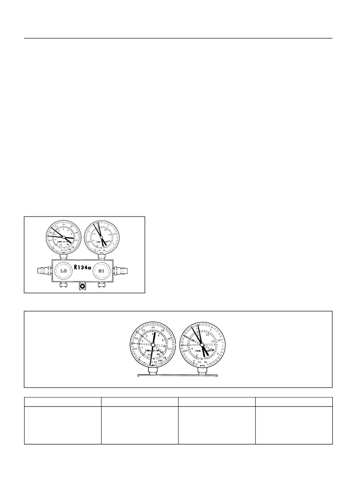
1.
INSPECT REFRIGERANT PRESSURE WITH MAN-
IFOLD GAUGE SET
(a) This is a method in witch the trouble is located by using
a manifold gauge set. Read the manifold gauge pressure
when the these conditions are established.
Test conditions:
F
Temperature at the air inlet with the switch set
at RECIRC is 30 - 35 °C (86 - 95 °F)
F
Engine running at 1500 rpm
F
Blower speed control switch at ”HI” position
F
Temperature control dial at ”COOL” position
F
A/C switch ON
F
Fully open doors
(1)
Normally functioning refrigeration system.
Gauge reading:
Low pressure side:
0.15 - 0.25 MPa (1.5 - 2.5 kgf/cm 2)
High pressure side:
1.37 - 1.57 MPa (14 - 16 kgf/cm 2)
E50573
(2)
Moisture present in refrigeration system.
Condition : Periodically cools and then fails to cool
I22117
Symptom
Probable cause
Diagnosis
Remedy
Moisture in refrigerating system
F Drier in oversaturected state
(1) Replace condenser
During operation, pressure on low
freezes at expansion valve orifice
F Moisture in refrigerating system
(2) Remove moisture in cycle by
pressure side sometimes become
causing a temporary stop of cycle,
freezes at expansion valve orifice
repeatedly evacuating air
a vacuum and sometime normal
however, when it melts, normal
and blocks circulation of refriger-
(3) Supply proper amount of new
state is restored.
ant
refrigerant

55-7
HEATER & AIR CONDITIONER
- REFRIGERANT
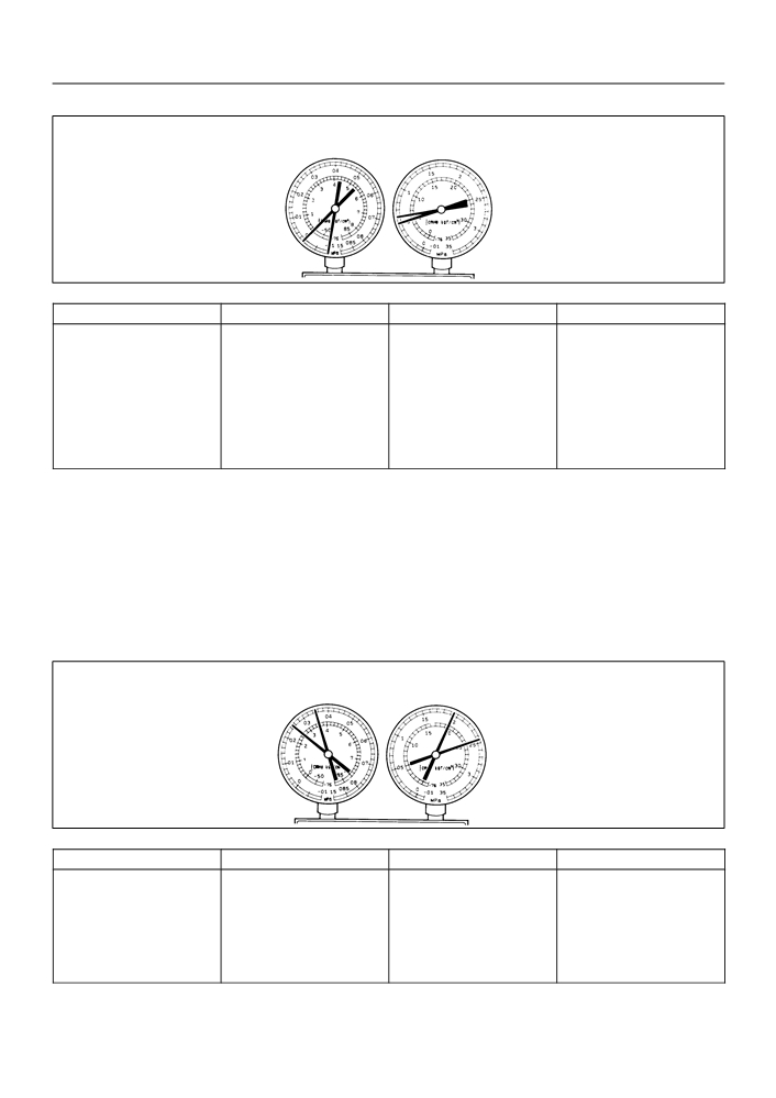
(3)
Insufficient cooling
Condition: Cooling system does not function eftectively.
I22118
Symptom
Probable cause
Diagnosis
Corrective Actions
(1) Check for gas leakage and re-
pair if necessary
(2) Supply proper amount of new
F Pressure low on both low and
refrigerant
Gas leakage in refrigeration sys-
F Insufficient refrigerant
high pressure sides
(3) If indicated pressure value is
tem
F Refrigerant leaking
F Insufficient cooling performance
close to a 0 when connected to
gauge, create the vacuum after in-
specting and repairing location of
leak
(4)
Poor circulation of refrigerant
Condition: Cooling system close not function effectively.
I22119
Symptom
Probable cause
Diagnosis
Corrective Action
F Pressure low on both low and
high pressure sides
Refrigerant flow obstructed by dirt
Receiver clogged
Replace condenser
F Frost on pipe from condenser to
in receiver
unit
55-8
HEATER & AIR CONDITIONER
- REFRIGERANT
(5)
Refrigerant does not circulate
Condition: Cooling system does not function. (Sometimes it way function)
I22120
Symptom
Probable cause
Diagnosis
Corrective Actions
(1) Check expansion valve
(2) Clean out dirt in expansion
F Vacuum indicated on low pres-
F Refrigerant flow obstructed by
valve by air blowing
sure side, very low pressure indi-
moisture or dirt in refrigerating sys-
(3) Replace condenser
cated on high pressure side
tem
Refrigerant does not circulate
(4) Evaporate air and supply prop-
F Frost or dew seen on piping be-
F Refrigerant flow obstructed by
er amount of new refrigerant.
fore and after receiver/ drier or ex-
gas leaked from expansion valve
(5) For gas leakage from expan-
pansion valve
sion valve, replace expansion
valve
(6)
Refrigerant overcharged or insufficient cooling of
condenser
Condition: Cooling system does not function dftectively.
I22121
Symptom
Probable cause
Diagnosis
Remedy
(1) Clean condenser
F Excessive refrigerant in
(2) Check cooling fan with cooling
F Unable to develop sufficient per-
cycletoo much refrigerant sup-
fan motor operation
F Pressure too high on both low
formance due to excessive use of
plied
(3) If (1) and (2) are in normal
and high pressure sides
refrigerating system
F Condenser cooling
state, check amount of refrigerant
F Insufficient cooling of condenser
insufficientcondenser fins
and supply proper amount of re-
clogged at cooling fan
frigerant