Toyota Corolla (2004+). Manual - part 101
16-3
COOLING
- COOLING SYSTEM (April, 2003)
160C5-04
INSPECTION
1.
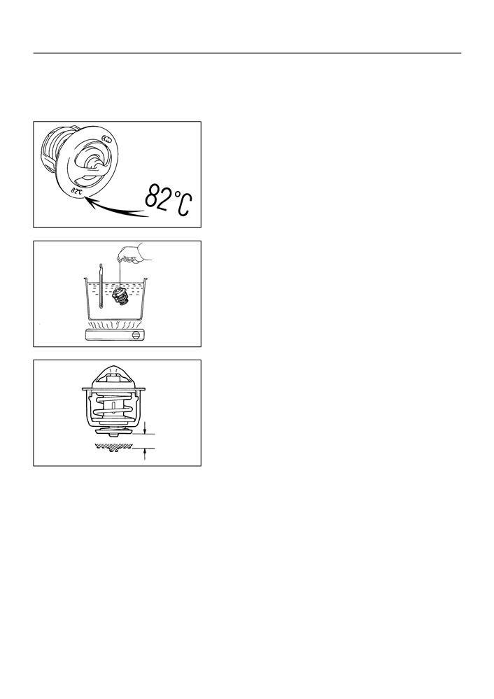
THERMOSTAT
HINT:
The thermostat is numbered with the valve opening tempera-
ture.
P13560
(a) Immerse the thermostat in water and gradually heat the
water.
(b) Check the valve opening temperature.
Valve opening temperature:
80 to 84 _C (176 to 183 _F)
HINT:
If the valve opening temperature is not as specified, replace the
thermostat.
P00436
(c)
Check the valve lift.
Valve lift: 10 mm (0.39 in.) or more at 95
_C (203_F)
HINT:
If the valve lift is not as specified, replace the thermostat.
(d) Check that the valve is fully closed when the thermostat
is at low temperatures (below 77_C (171_F)).
HINT:
If not closed, replace the thermostat.
P24125
2.
RADIATOR CAP SUB-ASSY
NOTICE:
F
If the radiator cap has contaminations, always rinse
it with water.
F
Before using a radiator cap tester, wet the relief valve
and pressure valve with engine coolant or water.
F
When performing step (a) and (b) below, keep the tes-
ter at an angle of over 30
_ above the horizontal.
16-4
COOLING
- COOLING SYSTEM (April, 2003)
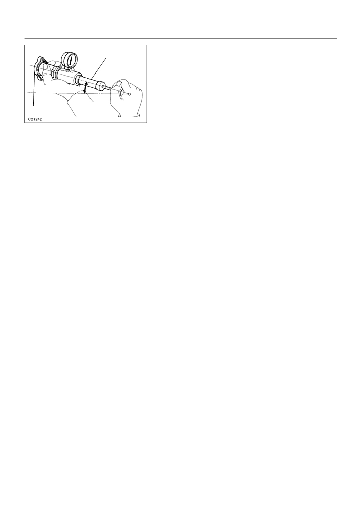
(a) Using a radiator cap tester, slowly pump the tester and
Radiator Cap Tester
check that air is coming from the vacuum valve.
Pump speed: 1 push / 3 seconds or more
NOTICE:
Push the pump at a constant speed.
30_ or more
If air is not coming from the vacuum valve, replace the radiator
cap.
Radiator Cap
(b) Pump the tester and measure the relief valve opening
Z00570
pressure.
Pump speed: 1 push within 1 second
NOTICE:
The above pump speed is for the first pump only (in order
to close the vacuum valve). After the first pump, the pump
speed can be reduced.
Standard opening pressure:
74 to 103 kPa (0.75 to 1.05 kgf/cm 2, 10.7 to 14.9 psi)
Minimum opening pressure:
59 kPa (0.6 kgf/cm 2, 8.5 psi)
HINT:
Use the tester’s maximum reading as the opening pressure.
If the opening pressure is less than minimum, replace the radia-
tor cap.
16-1
COOLING
- COOLING SYSTEM (April, 2003)
COOLING SYSTEM (April, 2003)
160NX-02
ON-VEHICLE INSPECTION
1.
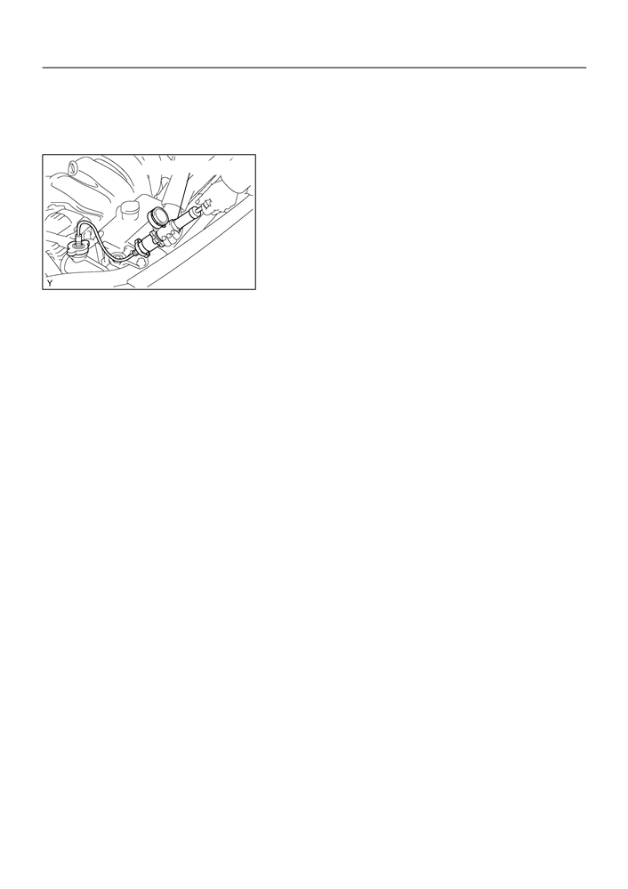
INSPECT COOLING SYSTEM FOR LEAKS
Radiator Cap Tester
CAUTION:
To avoid the danger of being burned, do not remove the ra-
diator cap while the engine and radiator are still hot, as fluid
and steam can be blown out under pressure.
(a) Fill the radiator with coolant and attach a radiator cap tes-
ter.
(b) Warm up the engine.
A65935
(c)
Pump it to 118 kPa (1.2 kgf/cm2, 17.1 psi), and check that
the pressure does not drop.
HINT:
If the pressure drops, check the hoses, radiator or water pump
for leaks. If no external leaks are found, check the heater core,
cylinder block and head.
2.
CHECK ENGINE COOLANT LEVEL AT RESERVOIR
(a) The engine coolant level should be between the ”LOW” and ”FULL” line.
HINT:
If low, check for leaks and add ”Toyota Long Life Coolant” or equivalent up to the ”FULL” line.
3.
CHECK ENGINE COOLANT QUALITY
(a) Remove the radiator cap.
CAUTION:
To avoid the danger of being burned, do not remove the radiator cap while the engine and radiator
are still hot, as fluid and steam can be blown out under pressure.
(b) Check if there is any excessive deposits of rust or scale around the radiator cap and radiator filler hole;
the coolant should be free from oil.
HINT:
If excessively dirty, replace the coolant.
(c)
Reinstall the radiator cap.
16-2
COOLING
- COOLING SYSTEM (April, 2003)
4.
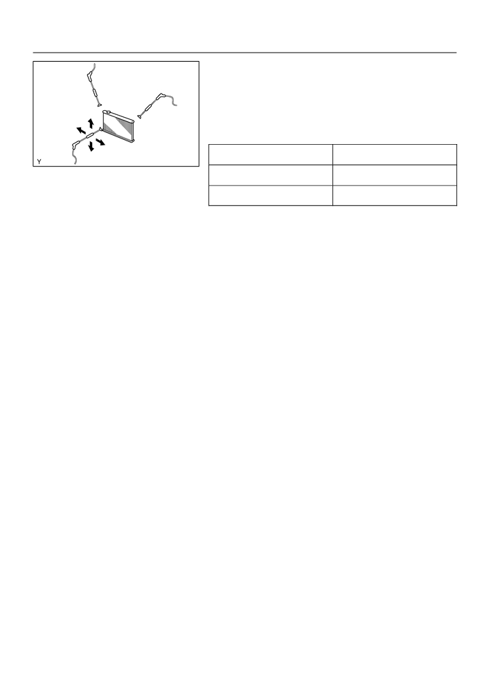
INSPECT FINS BLOCKAGE
(a) If fins are clogged, wash them with water or a steam
cleaner and dry with compressed air.
NOTICE:
F
If the distance between the steam cleaner and core is
too close, there is a possibility of damaging the fins,
so keep the following injection distance.
Injection Pressures
Injection Distance
kPa (kgf/cm2, psi)
mm (in.)
A73603
2,942 to 4,903
300 (11.811)
(30 to 50, 427 to 711)
4,903 to 7,845
500 (19.685)
(50 to 80, 711 to 1,138)
F
If the fins are bent, straighten them with a screwdriver
or pliers.
F
Be careful not pour water directly onto electronic
components.
16-13
COOLING
- RADIATOR ASSY
RADIATOR ASSY
160CC-02
REPLACEMENT
1.
DRAIN COOLANT(See page 16-7)
2.
SEPARATE RADIATOR HOSE INLET
3.
SEPARATE RADIATOR HOSE OUTLET
4.
SEPARATE OIL COOLER INLET TUBE NO.1
5.
SEPARATE OIL COOLER OUTLET TUBE NO.1
6.
REMOVE RADIATOR ASSY
(a) Disconnect the fan motor connector.
(b) Disconnect two clamps for wire-harness from fan-shroud.
(c)
Remove the two fan mount bolts.
(d) Remove the fan w/motor.
7.
ADD COOLANT (See page 16-7)
8.
CHECK ENGINE COOLANT LEAK (See page 16-7)
16-11
COOLING
- THERMOSTAT
THERMOSTAT
160CB-01
REPLACEMENT
1.
REMOVE ENGINE UNDER COVER RH
2.
DRAIN COOLANT (See page 16-7)
3.
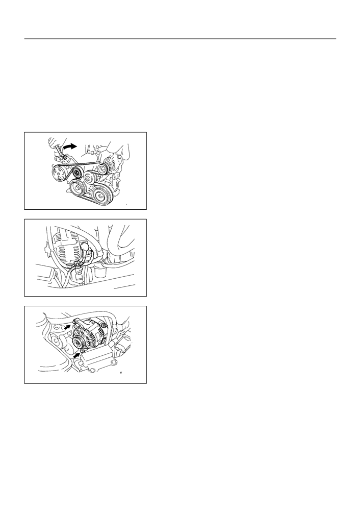
REMOVE FAN AND GENERATOR V BELT
(See page 14-4)
B00145
4.
REMOVE GENERATOR ASSY
(a) Disconnect the wire clamp from the wire clip on the recti-
fire end frame.
(b) Remove the rubber cap and nut, and disconnect the alter-
nator wire.
(c)
Disconnect the alternator connector.
B00143
(d) Remove the 2 bolts and alternator.
B00147
5.
REMOVE WATER INLET
6.
REMOVE THERMOSTAT

16-12
COOLING
- THERMOSTAT
7.
INSTALL THERMOSTAT
(a) Install a new gasket to the thermostat.
10F
10F
(b) Install the thermostat with the jiggle valve upward as
shown in the illustration.
A62118
8.
INSTALL WATER INLET
Torque: 11 N m (113 kgf cm, 8 ft lbf)
9.
INSTALL GENERATOR ASSY
Torque:
12mm head 25 N m (250 kgf cm, 18 ft lbf)
14mm head 54 N m (550 kgf cm, 39 in. lbf)
10. ADD COOLANT (See page 16-7)
11. CHECK ENGINE COOLANT LEAK (See page 16-7)
16-10
COOLING
- WATER PUMP ASSY
160CA-01
INSPECTION
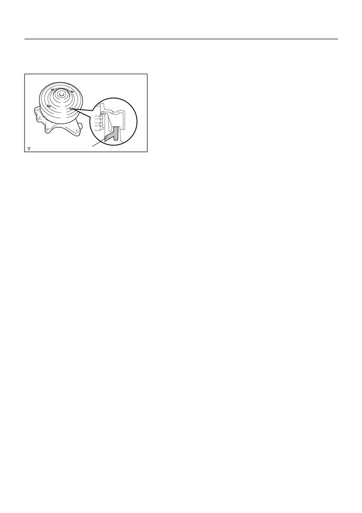
1.
INSPECT WATER PUMP ASSY
(a) Visually check the drain hole for coolant leakage.
Hole
B10233

16-8
COOLING
- WATER PUMP ASSY
WATER PUMP ASSY
160C9-01
REPLACEMENT
1.
REMOVE ENGINE UNDER COVER RH
2.
DRAIN COOLANT (See page 16-7)
3.
REMOVE FAN AND GENERATOR V BELT
(See page 14-4)
B00145
4.
REMOVE GENERATOR ASSY
(a) Disconnect the wire clamp from the wire clip on the recti-
fire end frame.
(b) Remove the rubber cap and nut, and disconnect the alter-
nator wire.
(c)
Disconnect the alternator connector.
B00143
(d) Remove the 2 bolts and alternator.
B00147
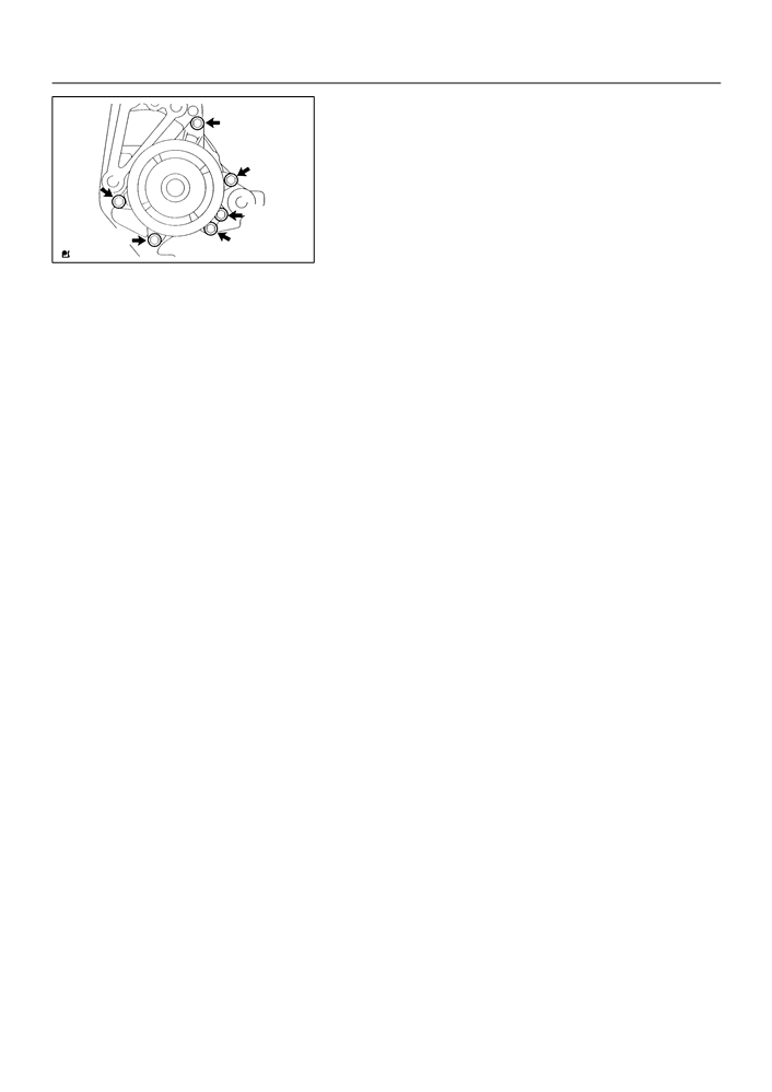
5.
REMOVE WATER PUMP ASSY
(a) Remove the 6 bolts, water pump and O-ring.
B00150
16-9
COOLING
- WATER PUMP ASSY
6.
INSTALL WATER PUMP ASSY
B
(a) Place a new O-ring on the timing chain cover.
(b) Install the water pump with the 6 bolts.
Torque:
B
Bolt A 9.0 N m (92 kgf cm, 80 in lbf)
A
Bolt B 11 N m (113 kgf cm, 8 ft lbf)
B
B
A
A32555
7.
INSTALL GENERATOR ASSY
Torque:
12 mm head 25 N m (250 kgf cm, 18 ft lbf)
14 mm head 54 Nm (550 kgf cm, 39 ft lbf)
8.
ADD COOLANT (See page 16-7)
9.
CHECK ENGINE COOLANT LEAK (See page 16-7)
55-15
HEATER & AIR CONDITIONER
- AIR CONDITIONING UNIT ASSY
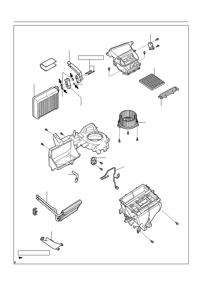
AIR CONDITIONER UNIT ASSY
550IU-01
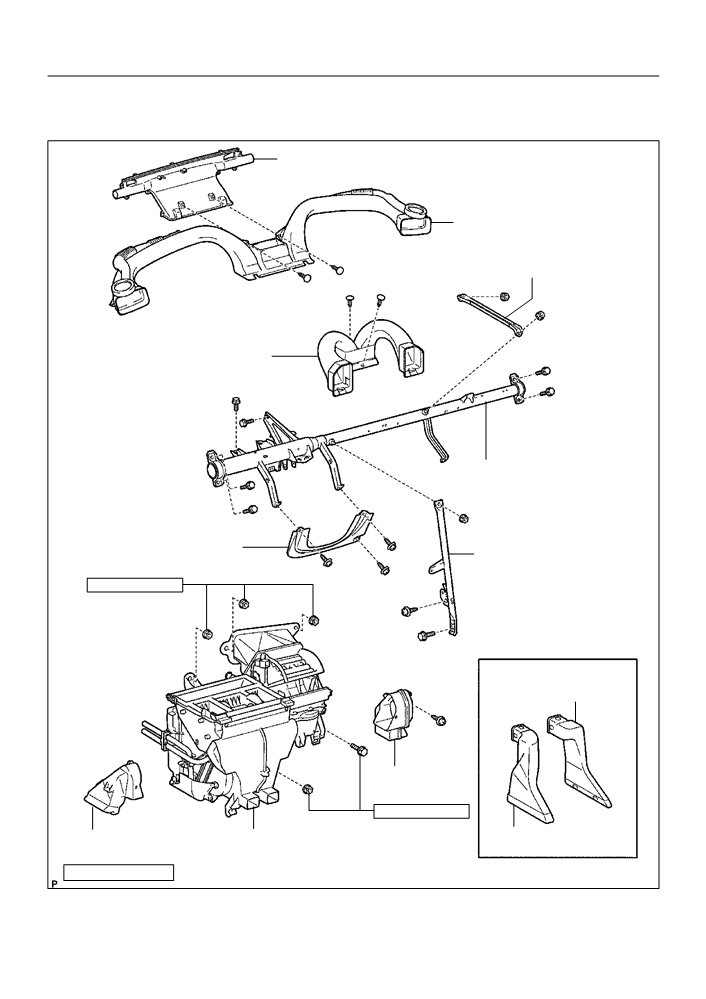
COMPONENTS
Defroster Nozzle Assy
Heater to Register Duct No.1
Instrument Panel to Cowl
Brace Center
Heater to Register
Duct No.2
Instrument Panel Reinforcement
Instrument Panel LWR
Instrument Panel Brace
Insert LH
Sub-assy No.1
9.8 (100, 87 in. lbf)
w/ Cold Area:
Air Duct Rear No.4
Air Duct No.2
9.8 (100, 87 in. lbf)
Air Duct No.1
Air Conditioner Unit Assy
Air Duct Rear No.3
Nm (kgfcm, ftlbf)
: Specified torque
I32531
55-16
HEATER & AIR CONDITIONER
- AIR CONDITIONING UNIT ASSY
Damper Servo Sub-assy
Air Conditioning Tube Assy
3.5 (35, 30 in. lbf)
Air Filter
_ O-Ring
Cooler Evaporator
Sub-assy No.1
_ O-Ring
_ O-Ring
Cooler Expansion Valve
Air Filter Case
Blower w/ fan Motor
Sub-assy
Blower Resistor
Cooler Thermistor No.1
Cooler Unit Drain Hose No.1
Heater Radiator Unit Sub-assy
Heater Piping Cover
Nm (kgfcm, ftlbf)
: Specified torque
Compressor Oil ND-OIL 8 or equivalent
_ Non-reusable Part
I32532

55-17
HEATER & AIR CONDITIONER
- AIR CONDITIONING UNIT ASSY
550IV-02
OVERHAUL
HINT:
COMPONENT: See page 55-15
1.
DISCHARGE REFRIGERANT FROM REFRIGERATION SYSTEM (See page 55-11)
SST
07110-58060 (07117-58080, 07117-58090, 07117-78050, 07117-88060, 07117-88070,
07117-88080)
2.
DISCONNECT COOLER REFRIGERANT SUCTION
HOSE NO.1
(a) Install SST to piping clamp.
SST
09870-00015
HINT:
SST
Confirm the direction of the piping clamp claw and SST using
the illustration showing on the caution label.
I03838
(b) Push down SST and release the clamp lock.
Push
Pull
NOTICE:
Be careful not to deform the tube, when pushing SST.
(c)
Pull SST slightly and push the release lever, then remove
the piping clamp with SST.
(d) Remove the piping clamp from SST.
SST
Release
Lever
I03839
(e) Disconnect the cooler refrigerant suction hose No. 1.
Disconnect the
NOTICE:
tube using hand
Screw
F
Do not use tools like screwdriver to remove the tube.
Driver
F
Cap the open fittings immediately to keep moisture or
dirt out of the system.
I06919
3.
DISCONNECT COOLER REFRIGERANT LIQUID PIPE A
SST
09870-00015
HINT:
Disconnect in the same way as the cooler refrigerant suction hose No. 1.
55-18
HEATER & AIR CONDITIONER
- AIR CONDITIONING UNIT ASSY
4.
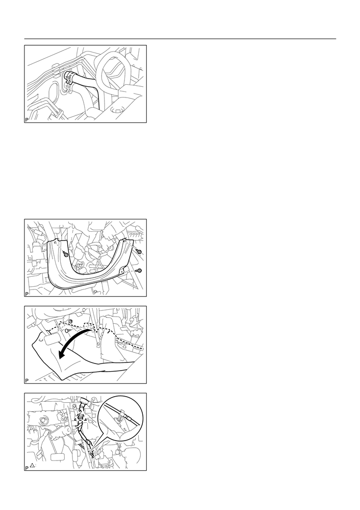
DISCONNECT HEATER INLET WATER HOSE
(a) Using pliers, grip the claws of clip and slide the clip and
disconnect the heater inlet water hose.
I32426
5.
DISCONNECT HEATER OUTLET WATER HOSE
HINT:
Disconnect in the same way as the heater inlet water hose.
6.
REMOVE INSTRUMENT PANEL SUB-ASSY LOWER (See page 71-10)
HINT:
Refer to the manuals for removal of the instrument panel sub-assy lower.
7.
REMOVE INSTRUMENT PANEL LWR PAD INSERT LH
(a) Remove the 3 screws and instrument panel LWR pad in-
sert LH.
I32436
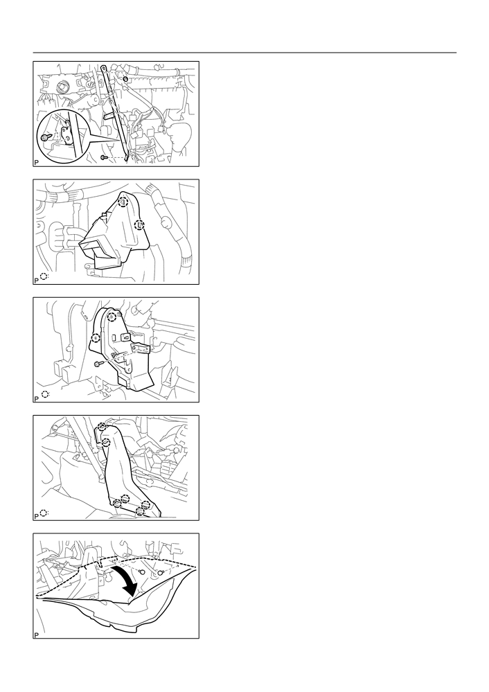
8.
REMOVE INSTRUMENT PANEL BRACE SUB-ASSY
NO.1
(a) Remove 2 clips and take up the floor carpet.
HINT:
Take up the floor carpet as small as the instrument panel brace
sub-assy No. 1 can be removed.
I32432
(b) Remove the clamp and floor shift parking lock cable assy.
Clamp
I32437
55-19
HEATER & AIR CONDITIONER
- AIR CONDITIONING UNIT ASSY
(c)
Remove the screw.
(d) Remove the bolt, nut and instrument panel brace sub-
assy No. 1.
I32438
9.
REMOVE AIR DUCT NO.1
(a) Release the 2 fitting claws, remove the air duct No. 1.
2 Claws
I32439
10. REMOVE AIR DUCT NO.2
(a) Remove the screw.
(b) Release the 2 fitting claws, remove the air duct No. 2.
2 Claws
I32440
11. REMOVE AIR DUCT REAR NO.3 (W/ COLD AREA)
(a) Release the 6 fitting claws, remove the air duct rear No.3.
6 Claws
I32433
12. REMOVE AIR DUCT REAR NO.4 (W/ COLD AREA)
(a) Remove 2 clips and take up the floor carpet.
HINT:
Take up the floor carpet as small as the air duct rear No.4 can
be removed.
I32434