Toyota Corolla (2004+). Manual - part 109

65-22
LIGHTING
- CENTER STOP LAMP ASSY
CENTER STOP LAMP ASSY
650GZ-01
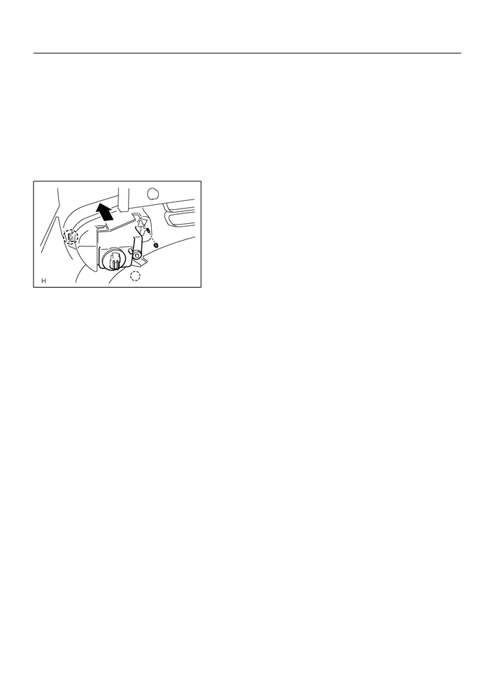
REPLACEMENT
1.
REMOVE PACKAGE TRAY TRIM PANEL ASSY (W/O REAR SPOILER)(See Page
61-15)
2.
REMOVE CENTER STOP LAMP ASSY (W/O REAR
SPOILER)
(a) Remove the center stop light assy as shown in the illustla-
tion.
Claw
E60611
3.
REMOVE CENTER STOP LAMP ASSY (W/ REAR
SPOILER)
(a) Remove the 2 screws.
(b) Disconnect the connector and remove the center stop
light assy.
E60461

65-12
LIGHTING
- LH HEADLAMP ASSY
LH HEADLAMP ASSY
650GR-01
COMPONENTS
Headlight Bulb No.1
Headlight Protector Retainer UPR LH
Headlight Bulb No.2
Headlight Protector Retainer LWR LH
Front Turn Signal Light Bulb
Headlight Unit LH
E60628

65-18
LIGHTING
- FOG LAMP ASSY LH
650GV-01
ADJUSTMENT
1.
PUT VEHICLE THESE CONDITIONS
(a) Tire inflation pressure is the specified value (See page 28-1).
(b) Start the engine.
2.
ADJUST FOG LIGHT AIM
(a) The fog light aim can be adjusting by moving the aiming
screw in the vertical direction.
HINT:
The optical aim moves upward when turning a screwdriver
clockwise, while it moves downward when turning a screwdriver
counterclockwise.
E60629
3.
CHECK FOG LIGHT AIM
65-17
LIGHTING
- FOG LAMP ASSY LH
FOG LAMP ASSY LH
650GU-01
REPLACEMENT
1.
REMOVE RADIATOR GRILLE SUB-ASSY(See page 76-2)
2.
REMOVE FRONT BUMPER COVER(See page 76-2)
3.
REMOVE FOG LAMP ASSY LH
(a) Remove a nut and release a claw.
(b) Remove the fog light assy LH.
Claw
E60622
4.
PUT VEHICLE THESE CONDITIONS(See page 65-18)
5.
ADJUST FOG LIGHT AIM(See page 65-18)
6.
CHECK FOG LIGHT AIM(See page 65-18)

65-23
LIGHTING
- HEADLAMP DIMMER SWITCH ASSY
HEADLAMP DIMMER SWITCH ASSY
650H0-01
REPLACEMENT
1.
REMOVE STEERING COLUMN COVER LWR
(a) Remove 3 screws and steering column cover LWR.
E60462
2.
REMOVE HEADLAMP DIMMER SWITCH ASSY
(a) Disconnect the connector.
(b) Release the claw and pull out the head light dimmer
switch assy.
Claw
E60467

65-7
LIGHTING
- LIGHTING SYSTEM (April, 2003)
650WO-01
INSPECTION
1.
HEADLAMP DIMMER SWITCH ASSY
Connector Front View:
(a) Inspect light control switch continuity.
C12
(1)
Measure the resistance according to the value(s) in
the table below.
Standard:
Tester connection
Switch operation
Specified resistance
10 - 11
11 - 12
OFF
10 kW or higher
10 - 13
E59482
10 - 13
TAIL
Below 1 W
10 - 13
HEAD
Below 1 W
11 - 12
(b) Inspect headlight dimmer switch continuity.
(1)
Measure the resistance according to the value(s) in
the table below.
Standard:
Tester connection
Switch operation
Specified resistance
8 - 11
FLASH
Below 1 W
9 - 11
8 - 11
LOW BEAM
Below 1 W
9 - 11
HI BEAM
Below 1 W
HINT:
Turn light control switch to the HEAD position when checking
”LOW BEAM” and ”HI BEAM”.
(c)
Inspect turn signal switch continuity.
(1)
Measure the resistance according to the value(s) in
the table below.
Standard:
Tester connection
Switch operation
Specified resistance
6 - 7
Right turn
Below 1 W
5 - 6
Neutral
10 kW or higher
6 - 7
6 - 5
Left turn
Below 1 W
(d) w/ Fog light:
Inspect front fog light switch continuity.
(1)
Measure the resistance according to the value(s) in
the table below.
Standard:
Tester connection
Switch operation
Specified resistance
2 - 4
OFF
10 kW or higher
2 - 4
ON
Below 1 W

65-8
LIGHTING
- LIGHTING SYSTEM (April, 2003)
2.
BACK UP LAMP SWITCH ASSY
(a) Measure the resistance according to the value(s) in the table below.
Standard:
Switch operation
Specified resistance
Ball is not pressed
10 kW or higher
Ball is pressed
Below 1 W
3.
STOP LAMP SWITCH ASSY (W/O CRUISE CONTROL)
(a) Measure the resistance according to the value(s) in the table below.
Standard:
Switch operation
Specified resistance
Switch pin free
10 kW or higher
Switch pin pushed in
Below 1 W
4.
STOP LAMP SWITCH ASSY (W/ CRUISE CONTROL)
2
1
(a) Measure the resistance according to the value(s) in the
table below.
Standard:
Tester connection
Switch operation
Specified resistance
1 - 2
Switch pin free
10 kW or higher
4
3
3 - 4
Switch pin free
Below 1 W
Free Pushed in
1 - 2
Switch pin pushed in
Below 1 W
3 - 4
Switch pin pushed in
10 kW or higher
E65594
5.
HAZARD WARNING SIGNAL SWITCH ASSY
Connector Front View:
(a) Measure the resistance according to the value(s) in the
H7
table below.
Standard:
Tester connection
Switch operation
Specified resistance
6
5
4
3
2 1
2 - 3
ON
Below 1 W
2 - 3
OFF
10 kW or higher
(b) Inspect illumination operation.
E59552
E69180
(1)
Connect the positive (+) lead from the battery to ter-
minal 5 and the negative (-) lead to terminal 4, then
check that the illumination comes on.
6.
FRONT DOOR COURTESY LAMP SWITCH ASSY
(a) Measure the resistance according to the value(s) in the table below.
Standard:
Switch operation
Specified resistance
Shaft is pressed
10 kW or higher
Shaft is not pressed
Below 1 W

65-9
LIGHTING
- LIGHTING SYSTEM (April, 2003)
7.
REAR DOOR COURTESY LAMP SWITCH ASSY
(a) Measure the resistance according to the value(s) in the table below.
Standard:
Switch operation
Specified resistance
Shaft is pressed
10 kW or higher
Shaft is not pressed
Below 1 W
8.
LUGGAGE COMPARTMENT ROOM COURTESY LAMP SWITCH ASSY
(a) Measure the resistance according to the value(s) in the table below.
Standard:
Switch operation
Specified resistance
Shaft is pressed
10 kW or higher
Shaft is not pressed
Below 1 W
9.
MAP LAMP ASSY (W/O SLIDING ROOF)
Connector Front View:
(a) Measure the resistance according to the value(s) in the
I12
table below.
Standard:
Tester connection
Switch operation
Specified resistance
1 - 6
OFF
10 kW or higher
(b) Connect the positive (+) lead from the battery to terminal
1 and the negative (-) lead to terminal 6, then check that
E69181
the illumination comes on when switch operation is ON
position.
10. MAP LAMP ASSY (W/ SLIDING ROOF)
Connector Front View:
(a) Measure the resistance according to the value(s) in the
M2
table below.
Standard:
Tester connection
Switch operation
Specified resistance
1 - 3
OFF
10 kW or higher
(b) Connect the positive (+) lead from the battery to terminal
1 and the negative (-) lead to terminal 3, then check that
E50229
the illumination comes on when switch operation is ON
position.

65-10
LIGHTING
- LIGHTING SYSTEM (April, 2003)
11. ROOM LAMP ASSY NO.1
Connector Front View:
(a) Connect the positive (+) lead from the battery to terminal
I13
1 and the negative (-) lead to terminal 2, then check that
the illumination comes on .
E50228
E69434
12. LUGGAGE COMPARTMENT LAMP ASSY NO.1
(a) Connect the positive (+) lead from the battery to terminal 1 and the negative (-) lead to terminal 2, then
check that the illumination comes on .
13. HEADLAMP RELAY
(a) Measure the resistance according to the value(s) in the
table below.
Standard:
Tester connection
Condition
Specified resistance
3 - 5
Always
10 kW or higher
Apply B+ between
3 - 5
Below 1 W
terminals 1 and 2
E33820
14. FOG LAMP RELAY
(a) Measure the resistance according to the value(s) in the
table below.
Standard:
Tester connection
Condition
Specified resistance
3 - 5
Always
10 kW or higher
Apply B+ between
3 - 5
Below 1 W
terminals 1 and 2
B16200
15. TAILLAMP RELAY
(a) Measure the resistance according to the value(s) in the
table below.
Standard:
Tester connection
Condition
Specified resistance
3 - 5
Always
10 kW or higher
Apply B+ between
3 - 5
Below 1 W
terminals 1 and 2
B16200

65-11
LIGHTING
- LIGHTING SYSTEM (April, 2003)
16. HEADLAMP DIMMER RELAY
(a) Measure the resistance according to the value(s) in the
table below.
Standard:
Tester connection
Condition
Specified resistance
3 - 5
Always
10 kW or higher
Apply B+ between
3 - 5
Below 1 W
terminals 1 and 2
E33820
17. LIGHT CONTROL RHEOSTAT
Maximum Position
(a) Connect the connector to the rheostat and inspect the
wire harness side connector from the back side as shown
R7
in the table below.
Standard:
Tester connection
Switch operation
Specified condition
1 - 3
Maximum position
Below 1 V
1 - 3
Minimum position
10 to 14 V
Minimum Position
3 - 7
OFF
10 to 14 V
E69179
3 - 7
ON
Below 1 V
(b) Inspect illumination operation.
(1)
Connect the positive (+) lead from the battery to ter-
minal 2 and the negative (-) lead to terminal 3, then
check that the illumination comes on.

65-13
LIGHTING
- LH HEADLAMP ASSY
650GS-01
REPLACEMENT
HINT:
COMPONENTS: See page 65-12
1.
REMOVE RADIATOR GRILLE SUB-ASSY(See page 76-2)
2.
REMOVE FRONT BUMPER COVER(See page 76-2)
3.
REMOVE LH HEADLAMP ASSY
(a) Remove the 3 bolts.
(b) Pull out the headlight assy LH forward, then disconnect
the bracket of body side.
E60619
(c)
Release the claws and disconnect the connectors as
shown in the illustration, and remove the headlight assy
LH.
Claw
E60621
4.
INSTALL RETAINER, HEADLAMP PROTECTOR, UPR
LH
HINT:
When only the installation part of the headlight assy LH is dam-
aged, it can be repaired inexpensively by using a headlight pro-
tector retainer UPR LH. In this case, however, the headlight
assy LH itself should not be damaged.
(a) Cut off the part shaded in the illustration and sand smooth
with sandpaper.
NOTICE:
After cutting off the part roughly, place the headlight pro-
tector retainer UPR LH against the bosses and gradually
file any interfering part until the proper condition for instal-
lation is made.
E60463

65-14
LIGHTING
- LH HEADLAMP ASSY
(b) Install the headlight protector retainer UPR LH with 2
screws.
E60464
5.
INSTALL RETAINER, HEADLAMP PROTECTOR, LWR
LH
(a) Cut off the part shaded in the illustration and sand smooth
with sandpaper.
2mm
NOTICE:
After cutting off the part roughly, place the headlight pro-
tector retainer LWR LH against the bosses and gradually
file any interfering part until the proper condition for instal-
lation is made.
E60465
(b) Install the headlight protector retainer LWR LH with a
screw.
E60466
6.
PUT VEHICLE THESE CONDITIONS(See page 65-18)
7.
ADJUST FOG LIGHT AIM(See page 65-18)
8.
HEADLIGHT AIM ONLY(See page 65-15)

65-20
LIGHTING
- LICENSE PLATE LAMP ASSY
LICENSE PLATE LAMP ASSY
650GX-01
REPLACEMENT
1.
REMOVE LUGGAGE COMPARTMENT LOCK CYLINDER & KEY SET(See Page 76-16)
2.
REMOVE LUGGAGE COMPARTMENT DOOR GARNISH OUTSIDE(See Page 76-16)
3.
REMOVE LICENSE PLATE LAMP ASSY
(a) Pull the license plate light assy to the side of vehicle as
shown in the illustration and release the claw.
(b) Disconnect the connector and remove the license plate
light assy.
E60618
4.
INSTALL SYMBOL EMBLEM(See Page 76-16)

65-4
LIGHTING
- LIGHTING SYSTEM (April, 2003)
650WN-01
ON-VEHICLE INSPECTION
1.
INSPECT TURN SIGNAL FLASHER RELAY CIRCUIT
Connector Front View:
(a) Disconnect the connector from the turn signal flasher
T2
relay and inspect the connector on wire harness side as
shown in the chart.
E15683
Standard:
Tester connection
Condition
Specified condition
7 - Ground
Constant
Below 1 W
1 - Ground
Ignition switch ON
10 to 14 V
1 - Ground
Ignition switch OFF
Below 1 V
4 - Ground
Constant
10 to 14 V
(b) Connect the connector to the turn signal flasher and in-
spect the wire harness side connector from the back side
as shown in the chart.
Standard:
Tester connection
Condition
Specified condition
0 V 0 Above 9 V
2 - Ground
Hazard warning signal switch OFF ON
(60 to 120 times per minute)
0 V 0 Above 9 V
2 - Ground
Turn signal switch (right turn) OFF ON
(60 to 120 times per minute)
0 V 0 Above 9 V
3 - Ground
Hazard warning signal switch OFF ON
(60 to 120 times per minute)
0 V 0 Above 9 V
3 - Ground
Turn signal switch (left turn) OFF ON
(60 to 120 times per minute)
5 - Ground
Turn signal switch (left turn) OFF ON
Above 9 V 0 V
6 - Ground
Turn signal switch (right turn) OFF ON
Above 9 V 0 V
8 - Ground
Hazard warning signal switch OFF ON
Above 9 V 0 V

65-5
LIGHTING
- LIGHTING SYSTEM (April, 2003)
2.
INSPECT DAYTIME RUNNING LIGHT RELAY
Connector Front View:
(a) Connect the connector to the daytime running light relay
D2
and inspect the wire harness side connector from the
back side as shown in the table below.
E69178
Standard:
Tester connection
Condition
Specified condition
1 - Body ground
Light control switch OFF or TAIL HEAD
Below 1 V Below 1 V
2 - Body ground
Always
Below 1 V
3 - Body ground
Always
10 to 14 V
4 - Body ground
Light control switch HEAD OFF or TAIL
Below 1 V 10 to 14 V
6 - Body ground
Light control switch OFF or TAIL HEAD
10 to 14 V Below 1 V
7 - Body ground
Light control switch OFF or TAIL HEAD
10 to 14 V Below 1 V
8 - Body ground
Engine stops Running
Below 1 V 10 to 14 V
10 - Body ground
Brake fluid level low Maximum
Below 1 V 10 to 14 V
11 - Body ground
Parking brake lever is released ON
10 to 14 V Below 1 V
12 - Body ground
Ignition switch OFF ON
Below 1 V 10 to 14 V
Light control switch OFF or TAIL
13 - Body ground
Light control switch HEAD and headlight dimmer
Below 1 V Below 1 V
switch is HIGH or FLASH
14 - Body ground (*1)
Light control switch OFF TAIL or HEAD
10 to 14 V Below 1 V
15 - Body ground (*1)
Light control switch OFF TAIL or HEAD
10 to 14 V Below 1 V
Headlight dimmer switch LOW
16 - Body ground
10 to 14 V Below 1 V
HIGH or FLASH
18 - Body ground (*1)
Always
Below 1 V
19 - Body ground (*1)
Ignition switch OFF ON
Below 1 V 10 to 14 V
20 - Body ground (*1)
Ignition switch OFF ON
Below 1 V 10 to 14 V
*1: USA only.