Toyota Corolla (2004+). Manual - part 88

11-32
FUEL
- FUEL TANK ASSY
36. INSTALL FUEL TANK ASSY
(a) Set a mission jack to the fuel tank.
(b) Install the fuel tank and 2 fuel tank bands with the 4 bolts.
Torque: 39 N m (400 kgf cm, 29 ft lbf)
37. CONNECT FUEL EMISSION TUBE SUB-ASSY NO.1
(a) Push in the fuel tube connector to the pipe until fuel tube connector makes ”click” sound.
NOTICE:
F
Check if there is any damage or foreign objects on the connected part.
F
After connecting, check if the fuel tube connector and pipe are securely connected by pulling
them.
38. CONNECT FUEL TANK MAIN TUBE SUB-ASSY
(a) Push in the fuel tube connector to pipe until fuel tube connector, and install the fuel tube connector
clip.
NOTICE:
F
Check if there is any damage or foreign objects on the connected part.
F
After connecting, check if the fuel tube connector and pipe are securely connected by pulling
them.
39. INSTALL PARKING BRAKE CABLE ASSY NO.3
(a) Install the parking brake cable with the 2 bolts.
Torque: 5.4 N m (55 kgf cm, 48 in. lbf)
40. INSTALL PARKING BRAKE CABLE ASSY NO.2
(a) Install the parking brake cable with the 2 bolts.
Torque: 5.4 N m (55 kgf cm, 48 in. lbf)
41. INSTALL FUEL TANK PROTECTOR NO.1
(a) Install the fuel tank protector with the 5 bolts.
Torque: 5.4 N m (55 kgf cm, 48 in. lbf)
42. INSTALL EXHAUST PIPE ASSY FRONT
(a) Using vernier calipers, measure the free length of the
compression spring.
Free length:
Wooden
Front side 43mm
(1.6929 in.)
Block
Rear side 40mm (1.5748 in.)
(b) Using a hammer and wooden block, tap in a new gasket
Gasket
until its surface is flush with the exhaust manifold.
A63953
NOTICE:
F
Tap in the gasket in the correct direction.
F
Do not reuse the removed gasket.
F
Be sure not to push in the gasket by installing the ex-
haust pipe.

11-33
FUEL
- FUEL TANK ASSY
(c)
Install a new gasket on the exhaust pipe (rear side).
(d) Install the exhaust pipe with the 4 compression springs
Tail Pipe Side
and 4 bolts.
Torque: 43 N m (440 kgf cm, 32 ft lbf)
(e) Install the 2 exhaust pipe supports.
(f)
Connect the oxygen sensor connector.
Gasket
(g) Install the font floor carpet with a clip.
A51891
43.
INSTALL FLOOR PANEL BRACE FRONT
(a)
Install the floor panel brace front with the 2 nuts.
Torque: 30 N m (302 kgf cm, 22 ft lbf)
44.
INSTALL FUEL SUCTION TUBE SET GASKET (See page
11-16)
45.
INSTALL FUEL PUMP ASSEMBLY (See page
11-16)
46.
INSTALL FUEL TANK VENT TUBE SET PLATE (See page
11-16)
47.
CONNECT FUEL EMISSION TUBE SUB-ASSY NO.1 (See page 11-16)
48.
CONNECT FUEL TANK MAIN TUBE SUB-ASSY (See page 11-16)
49.
CHECK FUEL LEAK (See page 11-1)
50.
CHECK EXHAUST GAS LEAK
51.
INSTALL REAR FLOOR SERVICE HOLE COVER (See page 11-16)
52.
INSTALL BENCH TYPE REAR SEAT CUSHION ASSY (See page
72-6, 72-8)

11-7
FUEL
- FUEL SYSTEM
110FH-01
INSPECTION
1.
FUEL INJECTOR ASSY
(a) Inspect injector resistance.
(1)
Using an ohmmeter,measure the resistance be-
tween the terminals.
2
1
Resistance: 13.4 - 14.2
W at 20_C (68_F)
A66088
(b) Inspect injector inspection
Fuel Tube Connector
CAUTION:
Keep injector clear of sparks during the test.
(1)
Purchase a new fuel tube, and take out the fuel tube
connector from its tube.
HINT:
Part No. 23901-0D010
A62159
(2)
Connect SST and fuel tube connector to the fuel
Fuel Tube Connector
pipe.
SST
09268-41047 (90467-13001, 95336-08070)
CAUTION:
SST (Hose)
Perform connecting operations of the fuel tube connector
(quick type) after observing the precautions.
SST (Clip)
A60555
(3)
Install an O-ring to the fuel injector.
SST (Hose)
(4)
Connect SST (union and hose) to fuel the injector,
SST
SST (Clip)
and hold the fuel injector to prevent gasoline from
(Adapter)
O-ring
splashing out. (See page 11-1)
SST
09268-41047 (90467-13001, 95336-08070,
SST
09268-41110, 09268-41300)
(Clamp)
Vinyl Tube
A62878

11-8
FUEL
- FUEL SYSTEM
(5)
Put the fuel injector into a graduated cylinder.
HINT:
Install a suitable vinyl tube onto the injector to prevent gasoline
SST
from splashing out.
(6)
Operate the fuel pump.
(7)
Connect SST to the connector of fuel injector.
SST
09842-30080
(8)
Connect SST to the battery for 15 seconds, and
A62879
measure the injection volume with a graduated cyl-
inder. Test the each fuel injector 2 or 3 time.
Injection volume:
60 - 73 cm 3 (3.7 - 4.5 cu in.) per 15 seconds
Difference between each injector:
13 cm 3 (0.8 cu in.) or less
(c)
Inspect leakage
(1)
In the condition above, disconnect the test probes
of the from the battery, and check the fuel leakage
from the fuel injector.
Fuel drop: 1 drop or less per 12 minutes
B00069
2.
FUEL PUMP
(a) Inspect fuel pump resistance.
(1)
Using an ohmmeter, measure the resistance be-
tween the terminals.
Resistance: 0.2 - 3.0
W at 20_C (68_F)
2
1
(b) Inspect fuel pump operation
(1)
Apply battery voltage to both terminals. Check that
the pump operates.
A66089
NOTICE:
F
These tests must be done quickly (within 10 seconds)
to prevent the coil from burning out.
F
Keep fuel pump as far away from the battery as pos-
sible.
F
Always do the switching at the battery side.

11-5
FUEL
- FUEL SYSTEM
110FG-01
ON-VEHICLE INSPECTION
1.
CHECK FUEL PUMP OPERATION
(a) Connect the hand-held tester to the DLC3.
3
2 1
(b) Turn the ignition switch ON and hand-held tester main
5 4
switch ON.
NOTICE:
Do not start the engine.
(c)
Select the active test mode on the hand-held tester.
(d) Please refer to the hand-held tester operator’s manual
A65704
for further details.
(e) If you have no hand-held tester, connect the positive (+)
lead form the battery to terminal 4 of the connecter, and
the negative (-) lead to terminal 5.
NOTICE:
F
These tests must be done quickly (within 10 seconds)
to prevent the coil burning out.
F
Keep the fuel pump as far away from the battery as
possible.
F
Always do the switching at the battery side.
2.
CHECK FUEL PRESSURE
Fuel Tube Connector
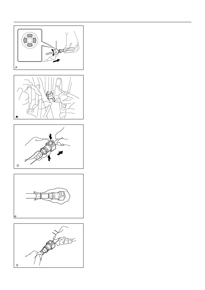
(a) Prepare for inspection.
(1)
Purchase a new fuel tube, and take out the fuel tube
connector from its tube.
HINT:
Part No. 23901-0D010
(b) Work for prevent gasoline from spilling out.
(See page 11-1)
A62159
(c)
Disconnect the EFI fuel pipe clamp. (See page 11-1)
(d) Disconnect the fuel tube from the fuel main tube.
(See page 11-1)
11-6
FUEL
- FUEL SYSTEM
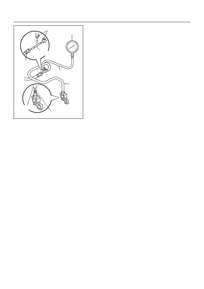
(e) Install SST (pressure gauge) as shown in the illustration
SST (Clip)
SST (Gauge)
by using the SST and fuel tube connector.
SST
09268-41047 (90467-13001, 95336-08070),
09268-45014 (09268-41200, 09268-41220,
09268-41250, 90467-13001)
(f)
Wipe off any splattered gasoline.
SST (T-joint)
(g) Start the engine.
(h) Measure the fuel pressure at idle.
Fuel Tube
Fuel pressure:
SST (Hose)
304 - 343 kPa (3.1 - 3.5 kgf cm 2, 44 - 50 psi)
(i)
Stop the engine.
(j)
Check that the fuel pressure remains as specified for 5
SST
minutes after the engine has stopped.
Fuel pressure:
147 kPa (1.5 kgf cm 2, 21 psi) or more
If pressure is not as specified, check the fuel pump, pressure
regulator and/or injectors.
SST (Hose)
(k)
After checking fuel pressure, disconnect the negative (-)
Fuel Tube Connector
A65093
terminal cable from the battery and carefully, remove the
SST and fuel tube connector to prevent gasoline from the
splashing.
(l)
Reconnect the fuel tube to fuel main tube.
(m) Install the EFI fuel pipe clamp.
(n) Check fuel leak. (See page 11-1)

11-1
FUEL
- FUEL SYSTEM
FUEL SYSTEM
110FF-01
PRECAUTION
1.
BEFORE WORKING ON FUEL SYSTEM, DISCONNECT NEGATIVE (-) TERMINAL CABLE FROM
BATTERY
2.
DO NOT SMOKE OR WORK NEAR AN OPEN FLAME WHEN WORKING ON FUEL SYSTEM
3.
KEEP GASOLINE AWAY FROM RUBBER OR LEATHER PARTS
4.
WORK FOR PREVENT GASOLINE FROM SPILLING
OUT
(a)
Remove the rear seat cushion.
(See page 72-6, 72-8)
(b)
Remove rear floor service hole cover.
(See page 11-16)
(c)
Disconnect the fuel pump connector.
(d)
Start the engine. After the engine has stopped on its own,
A65618
turn the ignition switch to lock.
(e)
Disconnect negative (-) terminal cable from battery.
(f)
Connect the fuel pump connector.
(g)
Install rear floor service hole cover. (See page 11-16)
(h)
Install the rear seat cushion.
(See page 72-6, 72-8)
5.
FUEL SYSTEM
(a)
When disconnecting the high fuel pressure line, a large
amount of gasoline will spill out, so observe these proce-
dures.
(1)
Work for prevent gasoline from spilling out.
(2)
Disconnect the fuel tank main tube.
(3)
Drain the fuel remained inside the fuel tank main
tube.
A62151
(4)
Protect the disconnected fuel tank main tube from
damage and foreign material by covering it with a vi-
nyl bag.
(5)
Put a container under the connection.
B07739

11-2
FUEL
- FUEL SYSTEM
(b) Observe these precautions when removing and installing
Correct
O-ring
the fuel injector.
(1)
Never reuse an O-ring.
(2)
When placing a new O-ring on the fuel injector, take
Injector
care not to damage it in any way.
Delivery Pipe
(3)
Coat a new O-ring with spindle oil or gasoline be-
Wrong
fore installing.
NOTICE:
A62152
Never use engine, gear or brake oil.
(c)
Install the fuel injector to the fuel delivery pipe and cylin-
Delivery Pipe
der head, as shown in the illustration. Before installing the
fuel injector, be sure to apply spindle oil or gasoline on the
place where the fuel delivery pipe touches an O-ring of
Insulator
the fuel injector.
O-ring
A65703
(d) Observe these precautions when disconnecting the fuel
delivery pipe.
O-ring
Retainer
Pipe
HINT:
The structure of the metallic connector is shown as illustration.
Nylon Tube
Housing
A62154
(1)
Remove the EFI fuel pipe clamp.
(2)
Get the metallic connector of the fuel tube assem-
bly, pull it out towards the rear and hold it as it is.
A65080
(3)
Assemble SST to the connection as shown.
SST
09268-21010
SST
A62165
11-3
FUEL
- FUEL SYSTEM
(4)
Turn SST, align the retainers inside the connector
with SST chamfered parts and insert SST into the
connector.
SST
(5)
Slide SST and the connector together towards the
fuel tube assembly.
Retainer
(at 4 places)
Insert
A62156
(e) Observe these precautions when disconnecting the fuel
tube connector (quick type).
(1)
Remove the EFI fuel pipe clamp.
(2)
Check if there is any dirt like mud on the pipe and
around the connector before disconnecting them
and clean the dirt away.
A65012
(3)
Be sure to disconnect with hands.
Push
(4)
When the connector and the pipe are stuck, pinch
the retainer between the hands, push and pull the
connector to free to disconnect and pull it out.
NOTICE:
Pull
Do not use any tool at this time.
(5)
Inspect if there is any dirt or the likes on the seal sur-
face of the disconnected pipe and clean it away.
A62157
(6)
Prevent the disconnected pipe and connector from
damaging and mixing foreign objects by covering
them with a vinyl bag.
B09222
(f)
Observe these precautions when connecting the fuel
tube connector (quick type).
(1)
Match the axis of the connector with axis of the pipe,
and push in the connector until retainer makes a
”click” sound. In case that the connections is tight,
apply little amount of new engine oil on the tip of the
pipe.
(2)
After having finished the connection, check if the
A56654
pipe and the connector are securely connected by
pulling them.

11-4
FUEL
- FUEL SYSTEM
6.
CHECK FUEL LEAK
(a) Check that there are no fuel leaks after doing mainte-
3
2 1
nance anywhere on the fuel system.
5 4
(1)
Connect the hand-held tester to the DLC3.
(2)
Turn the ignition switch ON and hand-held tester
main switch ON.
(3)
Select the active test mode on the hand-held tester.
(4)
Please refer to the hand-held tester operator’s
A65704
manual for further details.
(5)
If you have no hand-held tester, connect the posi-
tive (+) and negative (-) leads from the battery to the
fuel pump connector.
(6)
Check that there are no leaks from any part of the
fuel system.
(7)
Turn the ignition switch to LOCK.
(8)
Disconnect the hand-held tester from the DLC3.

12-6
EMISSION CONTROL
- EMISSION CONTROL SYSTEM
1204E-01
INSPECTION
1.
CHARCOAL CANISTER ASSY
(a) Visually check the charcoal canister for cracks or dam-
age.
A63966
(b) Inspect the charcoal canister operation.
Purge Port
EVAP Port
(1)
Plug the vent port with the cap.
Vent Port
(2)
While holding the purge port closed, blow air (1.76
Air Drain Port
kPa, 18 gf/cm2, 0.26 psi) into the EVAP port and
check that air flows from the air drain port.
Cap
Air
A63968
(3)
While holding the purge port and the air drain port
Air Inlet Port
Purge Port
closed, blow air (1.76 kPa, 18 gf/cm2, 0.26 psi) into
EVAP Port
Air Drain Port
the EVAP port and check that air does not flow from
the air inlet port.
Air
A63970
(4)
Apply vaccum (3.43 kPa, 25.7 mmHg, 1.01 in.Hg)
to the purge port, check that the vacuum dose not
Air Inlet
decrease when the air inlet port is closed, and
Port
check that the vacuum decreases when the air inlet
port is released.
Vacuum Purge Port
A63972

12-7
EMISSION CONTROL
- EMISSION CONTROL SYSTEM
(5)
While holding the air inlet port closed, apply vacuum
Purge Port
Air Inlet
(3.43 kPa, 25.7 mmHg, 1.01 in.Hg) to the EVAP port
Port
and check that air flows into the purge port.
If operation is not as spacified, replace the charcoal canister.
(6)
Remove the hose and cap from vent port.
Vacuum
EVAP Port
A65903
(c)
Inspect VSV for Pressure Swiching Valve
Ohmmeter
(1)
Using an ohmmeter, check that there is continuity
between the terminals.
Resistance: 37 - 44
W at 20FC (68FF)
If there is no continuity, replace the VSV.
Continuity
A65908
Ohmmeter
(2)
Using an ohmmeter, check that there is no continu-
ity between each terminal and the body.
If there is continuity, replace the VSV.
No Continuity
A65909
(3)
Check that air does not flow from ports E to F.
F
E
Air
A65910
(4)
Apply battery positive voltage across the terminals.
(5)
Check that air flows from ports E to F.
If operation is not as specified, replace the VSV.
F
E
Battery
Air
A65911

12-8
EMISSION CONTROL
- EMISSION CONTROL SYSTEM
2.
VENTILATION VALVE SUB-ASSY
Cylinder Head Side
(a) Install clean hose to the PCV valve.
(b) Inspect the PCV valve operation.
Clean Hose
(1)
Blow air into the cylinder head side, and check that
air passes through easily.
CAUTION:
Do not suck air through the valve. Petroleum substances
inside the valve air harmful.
P11834
(2)
Blow air into the intake manifold side, and check
Intake Manifold Side
that air passes through with difficulty.
If operation is not as specified, replace the PCV valve.
(c)
Remove clean hose from the PCV valve.
P11831
3.
FUEL TANK CAP ASSY
(a) Visually check if cap and/or gasket are deformed or dam-
aged.
If necessary, repair or replace the cap.
Gasket
B11870
4.
VACUUM SWITCHING VALVE NO.1
Ohmmeter
(a) Inspect VSV for evaporative emission (EVAP).
(1)
Using an ohmmeter, check that there is continuity
between the terminals.
Resistance: 27 - 33
W at 20FC (68FF)
If there is no continuity, replace the VSV.
Continuity
A65912
(2)
Using an ohmmeter, check that there is no continu-
Ohmmeter
ity between each terminal and the body.
If there is continuity, replace the VSV.
No Continuity
A65913

12-9
EMISSION CONTROL
- EMISSION CONTROL SYSTEM
(3)
Check that air flows from ports E to F.
Air
E
F
A65914
(4)
Apply battery positive voltage across the terminals.
(5)
Check that air does not flow from ports E to F.
Air
If operation is not as specified, replace the VSV.
E
F
Battery
A65915
5.
VACUUM SWITCHING VALVE ASSY NO.1
Ohmmeter
Continuity
(a) Inspect VSV for Canister Closed valve (CCV).
(1)
Using an ohmmeter, check that there is continuity
between the terminals.
Resistance: 25 - 30
W at 20FC (68FF)
If there is no continuity, replace the VSV.
A65916
(2)
Using an ohmmeter, check that there is no continu-
Ohmmeter
No Continuity
ity between each terminal and the body.
If there is continuity, replace the VSV.
A65917
(3)
Check that air flows from ports A to B.
B
Air
A
A65918

12-10
EMISSION CONTROL
- EMISSION CONTROL SYSTEM
(4)
Apply battery positive voltage across the terminals.
(5)
Check that air does not flow from ports A to B.
If operation is not as specified, replace the VSV.
B
Air
A
Battery
A65919