Toyota Corolla (2004+). Manual - part 87
11-17
FUEL
- FUEL PUMP ASSY
5.
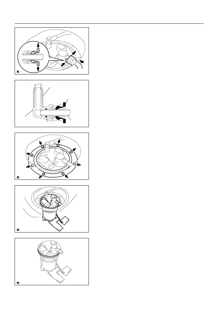
DISCONNECT FUEL EMISSION TUBE SUB-ASSY
NO.1
(a) Pinch the fuel tube connector clip and then pull out the
fuel emission tube.
NOTICE:
F
Check if there is any dirt like mud around the fuel tube
connector before this work and clean dirt away.
F
Be careful of dirt like mud because the fuel tube con-
A65025
nector has an O-ring to seal the fuel tube connector
and pipe.
F
Do not use any tool in this work.
Nylon Tube
F
Do not bend or twist the nylon tube by force.
Fuel Tube
F
After disconnecting, cover the fuel tube connector
Connector Clip
with a vinyl bag.
F
When the fuel tube connector and pipe are stuck,
pinch the fuel emission tube between fingers, and
turn it carefully to free and then disconnect the fuel
Fuel Tube
emission tube.
Connector
O-ring
Pipe
A60576
6.
REMOVE FUEL TANK VENT TUBE SET PLATE
(a) Remove the 8 bolts and fuel tank vent tube set plate.
A65026
7.
REMOVE FUEL PUMP ASSEMBLY
(a) Pull out the fuel pump assembly.
NOTICE:
F
Do not damage the fuel pump filter.
F
Be careful that the arm of the fuel sender gauge
should not bent.
A65027
8.
REMOVE FUEL SUCTION TUBE SET GASKET
(a) Remove the gasket from the fuel pump assembly.
A65028

11-18
FUEL
- FUEL PUMP ASSY
9.
REMOVE FUEL SUCTION SUPPORT NO.2
(a) Using a screwdriver, disconnect the 5 snap claws from the
claw holes, and remove the fuel suction support.
NOTICE:
Do not damage the fuel suction support.
A65029
10. REMOVE FUEL PUMP CUSHION RUBBER
(a) Remove the fuel pump cushion rubber.
A65030
11. REMOVE FUEL SENDER GAGE ASSY
(a) Disconnect the fuel sender gage connector.
(b) Using a screwdriver, unlock the fuel sender gage, and
slide it remove.
A65031
12. REMOVE FUEL SUCTION PLATE SUB-ASSY
(a) Disconnect the fuel pump connector.
(b) Using a screwdriver, disconnect the 4 snap claws from the
claw holes, and remove the fuel suction plate.
NOTICE:
Do not damage the fuel suction plate.
A65032
13. REMOVE VAPOR PRESSURE SENSOR ASSY
(a) Remove the tube joint clip, and pull out the vapor pres-
sure sensor.
A65033

11-19
FUEL
- FUEL PUMP ASSY
14. REMOVE FUEL PUMP HARNESS
(a) Remove the fuel pump harness from the fuel suction
plate.
A65034
15. REMOVE FUEL PUMP
(a) Pull out the fuel pump from the fuel filter.
A65035
16. REMOVE FUEL PUMP FILTER
(a) Using a small screwdriver, pry out the clip.
(b) Pull out the fuel pump filter from the fuel pump.
A65036
17. REMOVE FUEL PRESSURE REGULATOR ASSY
(a) Pull out the fuel pressure regulator from the fuel filter.
A65037
18. REMOVE FUEL PRESSURE REGULATOR O-RING
(a) Remove an O-ring from the fuel pressure regulator.
A65038

11-20
FUEL
- FUEL PUMP ASSY
19. INSTALL FUEL PRESSURE REGULATOR O-RING
Apply a light coat
(a) Apply a light coat of gasoline to a new O-ring, and install
of gasoline
it to the fuel pressure regulator.
A65038
20. INSTALL FUEL PUMP FILTER
(a) Install the fuel pump filter with a new clip.
21. INSTALL FUEL PUMP
Apply a light coat
(a) Apply a light coat of gasoline to an O-ring, and install the
of gasoline
fuel pump to the fuel filter.
A65040
22. INSTALL VAPOR PRESSURE SENSOR ASSY
(a) Install the vapor pressure sensor with the tube joint clip.
NOTICE:
F
Check that there is no scratch or foreign objects on the connecting parts.
F
Check that the fuel tube joint is inserted fully and securely.
F
Check that the tube joint clip is on the collar of the fuel tube joint.
F
After installing the tube joint clip, check that the fuel tube joint is not pulled off.
23. INSTALL FUEL SUCTION TUBE SET GASKET
(a) Install a new gasket to the fuel pump assembly.
24. INSTALL FUEL PUMP ASSEMBLY
(a) Install the fuel pump assembly to the fuel tank.
NOTICE:
F
Do not damage the fuel pump filter.
F
Be careful that the arm of the fuel sender gauge should not bent.
25. INSTALL FUEL TANK VENT TUBE SET PLATE
(a) Install the fuel tank vent tube set plate with the 8 bolts.
Torque: 6.0 N m (61 kgf cm, 53 in. lbf)
26. CONNECT FUEL EMISSION TUBE SUB-ASSY NO.1
(a) Push in the fuel emission tube to the pipe until fuel tube connector makes ”click” sound.
NOTICE:
F
Check if there is any damage or foreign objects on the connected part.
F
After connecting, check if the fuel tube connector and pipe are securely connected by pulling
them.

11-21
FUEL
- FUEL PUMP ASSY
27. CONNECT FUEL TANK MAIN TUBE SUB-ASSY
(a) Connect the fuel tank main tube with the tube joint clip.
NOTICE:
F
Check that there is no scratch or foreign objects on the connecting parts.
F
Check that the fuel tube joint is inserted fully and securely.
F
Check that the tube joint clip is on the collar of the fuel tube joint.
F
After installing the tube joint clip, check that the fuel tube joint is not pulled off.
28. CHECK FUEL LEAK (See page 11-1)
29. INSTALL REAR FLOOR SERVICE HOLE COVER
(a) Using the butyl tape, install the rear floor service hole cov-
er.
Butyl Tape
A65023
30. INSTALL BENCH TYPE REAR SEAT CUSHION ASSY (See page
72-6, 72-8)

11-22
FUEL
- FUEL TANK ASSY
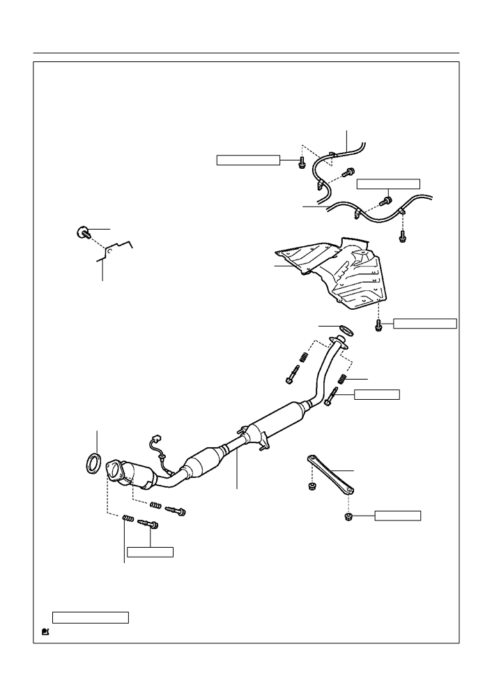
FUEL TANK ASSY
110FD-01
COMPONENTS
Rear Seat Cushion Assy
Rear Floor Service Hole Cover
Fuel Tank Main Tube Sub-assy
6.0 (61, 53 in. lbf)
Fuel Evaporation Tube Sub-assy No 2
X8
Fuel Tank Vent Tube Set Plate
Tube Joint Clip
Fuel Pump Assembly
F Gasket
N·m (kgf·cm, ft·lbf)
: Specified torque
F Non-reusable part
A65087
11-23
FUEL
- FUEL TANK ASSY
Parking Brake Cable Assy No. 2
5.4 (55, 48 in. lbf)
5.4 (55, 48 in. lbf)
Parking Brake Cable Assy No. 3
Clip
Fuel Tank Protector No. 1
Front Floor Carpet Assy Front
5.4 (55, 48 in. lbf)
F Gasket
X5
Compression Spring
43 (440, 32)
F Gasket
Floor Panel Brace Front
Exhaust Pipe Assy Front
30 (302, 22)
43 (440, 32)
Compression Spring
N·m (kgf·cm, ft·lbf)
: Specified torque
F Non-reusable part
A65709

11-24
FUEL
- FUEL TANK ASSY
Fuel Emission Tube
Check Valve Protector
Sub-assy No. 1
Fuel Tube Vent Hose
Valve
to Fuel Filler Pipe Hose
Fuel Tank Inlet Valve Assy
Fuel Tank Main Tube Sub-assy
F Gasket
F Fuel Tank Cushion No. 1
Fuel Tube Clamp No. 2
Fuel Tank Breather Hose
Fuel Tank Assy
Fuel Tank
to Filler Pipe Hose
Fuel Tube Bracket
6.0 (61, 53 in. lbf)
Fuel Tube Clamp No. 4
39 (400, 29)
Fuel Tank Band Sub-assy No. 1
Fuel Tank Band Sub-assy No. 1 LH
39 (400, 29)
N·m (kgf·cm, ft·lbf)
: Specified torque
F Non-reusable part
A65044

11-25
FUEL
- FUEL TANK ASSY
110FE-01
Removal & Installation and Disassembly & Reassembly
1.
REMOVE BENCH TYPE REAR SEAT CUSHION ASSY (See page 72-6, 72-8)
2.
REMOVE REAR FLOOR SERVICE HOLE COVER (See page 11-16)
3.
WORK FOR PREVENTING GASOLINE FROM SPILLING OUT
(a) Start the engine.
(b) After the engine has stopped on the its own, turn the ignition switch to lock.
4.
DISCONNECT FUEL TANK MAIN TUBE SUB-ASSY (See page 11-16)
5.
DISCONNECT FUEL EMISSION TUBE SUB-ASSY NO.1 (See page 11-16)
6.
REMOVE FUEL TANK VENT TUBE SET PLATE (See page 11-16)
7.
REMOVE FUEL PUMP ASSEMBLY (See page 11-16)
8.
REMOVE FUEL SUCTION TUBE SET GASKET
9.
DRAIN FUEL
10. REMOVE FLOOR PANEL BRACE FRONT
(a) Remove the 2 nuts and floor panel brace front.
A65046
11. REMOVE EXHAUST PIPE ASSY FRONT
(a) Using a clip remover, remove the clip.
Front Floor Carpet
(b) Tear off the front floor carpet.
A65047

11-26
FUEL
- FUEL TANK ASSY
(c)
Disconnect the oxygen sensor connector.
(d) Remove the 2 exhaust pipe supports.
(e) Remove the 4 bolts, 4 compression springs and exhaust
pipe.
A65706
12. REMOVE FUEL TANK PROTECTOR NO.1
(a) Remove the 5 bolts and fuel tank protector.
A65049
13. SEPARATE PARKING BRAKE CABLE ASSY NO.2
(a) Remove the 2 installing bolts of the parking brake cable.
A65050

11-27
FUEL
- FUEL TANK ASSY
14. SEPARATE PARKING BRAKE CABLE ASSY NO.3
(a) Remove the 2 installing bolts of the parking brake cable.
A65051
15. DISCONNECT FUEL TANK MAIN TUBE SUB-ASSY
(a) Pinch the fuel tube connector clip, and remove the fuel
tube connector clip.
(b) Pull out the fuel tank main tube.
NOTICE:
F
Check if there is any dirt like mud around the fuel tube
connector before this work and clean the dirt away.
F
Be careful of dirt like mud because the fuel tube con-
A65052
nector has an O-ring to seal the fuel tube connector
and pipe.
F
Do not use any tool in this work.
Fuel Tube
Nylon Tube
F
Do not bend or twist the nylon tube by force.
Connector Clip
F
After disconnecting, cover the fuel tube connector
with a vinyl bag.
F
When the fuel tube connector and pipe are stuck,
pinch the fuel tank main tube between fingers, and
turn it carefully to free and then disconnect the fuel
O-ring
Pipe
tank main tube.
Fuel Tube Connector
A66709
16. DISCONNECT FUEL TANK INLET PIPE FUEL HOSE
(a) Disconnect the fuel tank inlet filler pipe hose from the fuel
tank.
A65054
17. DISCONNECT FUEL TANK BREATHER HOSE
(a) Disconnect the fuel tank breather hose from the fuel tank.
A65055

11-28
FUEL
- FUEL TANK ASSY
18. DISCONNECT FUEL TANK VENT HOSE
Push
(a) Disconnect the fuel tank bent hose from the charcoal can-
ister.
Pinch
(1)
Push the connector deep inside.
(2)
Pinch portion A.
Pinch
A
(3)
Pull out the connector.
A
A65056
19. DISCONNECT VALVE TO FUEL FILLER PIPE HOSE
(a) Disconnect the valve to fuel filler pipe hose from the fuel
tank inlet pipe.
A65057
20. DISCONNECT FUEL EMISSION TUBE SUB-ASSY
NO.1
(a) Pinch the fuel tube connector clip and then pull out the
fuel emission tube.
NOTICE:
F
Check if there is any dirt like mud around the fuel tube
connector before this work and clean the dirt away.
F
Be careful of dirt like mud because the fuel tube con-
A65058
nector has an O-ring to seal the fuel tube connector
and pipe.
Fuel Tube
F
Do not use any tool in this work.
Nylon Tube
Connector Clip
F
Do not bend or twist the nylon tube by force.
O-ring
F
After disconnecting, cover the fuel tube connector
with a vinyl bag.
F
When the fuel tube connector and pipe are stuck,
pinch the fuel emission tube between fingers, and
turn it carefully to free and then disconnect the fuel
Pipe
Fuel Tube
emission tube.
Connector
A65059
21. REMOVE FUEL TANK ASSY
(a) Set a mission jack to the fuel tank.
(b) Remove the 4 bolts, 2 fuel tank bands and fuel tank.
A65060

11-29
FUEL
- FUEL TANK ASSY
22. REMOVE FUEL TANK MAIN TUBE SUB-ASSY
(a) Remove the fuel tank main tube from the fuel tube clamp
and bracket.
A65061
23. REMOVE FUEL TUBE CLAMP NO.4
(a) Remove the bolt and fuel tank clamp.
A65062
24. REMOVE FUEL TUBE BRACKET
(a) Remove the fuel tube bracket from the fuel tank.
A65063
25. REMOVE FUEL EMISSION TUBE SUB-ASSY NO.1
(a) Pinch the fuel tube connector clip and then pull out the
fuel emission tube.
NOTICE:
F
Check if there is any dirt like mud around the fuel tube
connector before this work and clean the dirt away.
F
Be careful of dirt like mud because the fuel tube con-
nector has an O-ring to seal the fuel tube connector
A65064
and pipe.
F
Do not use any tool in this work.
F
Do not bend or twist the nylon tube by force.
Nylon Tube
F
After disconnecting, cover the fuel tube connector
Fuel Tube
with a vinyl bag.
Connector Clip
F
When the fuel tube connector and pipe are stuck,
pinch the fuel emission tube between fingers, and
turn it carefully to free and then disconnect the fuel
emission tube.
Fuel Tube
Pipe
Connector
O-ring
A60576

11-30
FUEL
- FUEL TANK ASSY
26. REMOVE FUEL TUBE CLAMP NO.2
(a) Remove the fuel tube clamp from the fuel tank.
A65065
27. REMOVE CHECK VALVE PROTECTOR
(a) Using a screwdriver, unlock the claw, and remove the
check valve protector by turning it counter clockwise.
A65066
28. REMOVE FUEL TANK INLET VALVE ASSY
Clip Remover
(a) Insert a clip remover between the fuel tank inlet valve and
gasket, remove the fuel tank inlet valve by gradually
pushing it upward.
NOTICE:
F
Work accurately to maintain the sealing performance
of the fuel tank inlet valve, since it is made from resin.
It is easy to damage by removing and installing forci-
Gasket
A65067
bly.
F
Be sure to install a new fuel tank inlet valve and gas-
ket.
29. REMOVE CHECK VALVE GASKET
(a) Remove the gasket from the fuel tank inlet valve.
A65068

11-31
FUEL
- FUEL TANK ASSY
30. REMOVE FUEL TANK CUSHION NO.1
(a) Remove the 7 fuel tank cushions from the fuel tank.
A65069
31. INSTALL FUEL TANK CUSHION NO.1
(a) Install the 7 new fuel tank cushions to the fuel tank.
A65069
32. INSTALL CHECK VALVE GASKET
(a) Install a new gasket to the fuel tank.
A65070
33. INSTALL FUEL TANK INLET VALVE ASSY
(a) Apply a light coat of oil around the fuel tank inlet valve as
shown in the illustration, and insert it into the fuel tank
without force.
NOTICE:
Be careful not to drop the gasket into the fuel tank.
Apply a light coat
of oil
A65071
34. INSTALL FUEL EMISSION TUBE SUB-ASSY NO.1
(a) Push in the fuel tube connector to the pipe until fuel tube connector makes ”click” sound.
NOTICE:
F
Check if there is any damage or foreign objects on the connected part.
F
After connecting, check if the fuel tube connector and pipe are securely connected by pulling
them.
35. INSTALL FUEL TUBE CLAMP NO.4
(a) Install the fuel tube clamp with the bolt.
Torque: 6.0 N m (61 kgf cm, 53 in. lbf)