Toyota Corolla (2004+). Manual - part 86

05-698
DIAGNOSTICS
- WIRELESS DOOR LOCK CONTROL SYSTEM
13
CHECK DOOR CONTROL RECEIVER
(a) Reconnect the connector to the door control receiver, and
Door Control Receiver
check the voltage between the terminal and the body
ground, as shown in the illustration and table.
D3
B51174
Standard:
Symbols (Terminal No.)
Condition
Specified condition
No key in ignition key cylinder, all doors closed
RDA (D3-2) Body ground
1 V or less Approx. 6 - 7 V 1 V or less
and each transmitter switch OFF ON
NG Go to step 15
OK
14
CHECK WIRE HARNESS (DOOR CONTROL RECEIVER INSTRUMENT PANEL
J/B) (DOOR CONTROL RECEIVER OR INSTRUMENT PANEL J/B BODY
GROUND)
(a) Disconnect the door control receiver and instrument pan-
Door Control Receiver
(Wire Harness Side)
el J/B connectors.
D3
(b) Check the continuity between the terminals of the door
control receiver and instrument panel J/B connectors, as
shown in the illustration and table.
Standard:
Symbols (Terminal No.)
Specified condition
(Receiver - Instrument panel J/B)
RDA (D3-2) RDA (ID-8)
Continuity
RDA (D3-2) Body ground
Instrument Panel J/B
No continuity
RDA (ID-8) Body ground
(Wire Harness Side)
ID
NG REPAIR OR REPLACE HARNESS AND
CONNECTOR
B59377
OK

05-699
DIAGNOSTICS
-
WIRELESS DOOR LOCK CONTROL SYSTEM
15
REPLACE DOOR CONTROL RECEIVER WITH NORMAL ONE
NG Go to step 16
OK
REPLACE DOOR CONTROL RECEIVER
16
REPLACE INTEGRATION RELAY WITH NORMAL ONE
NG REPLACE INSTRUMENT PANEL JUNCTION
BLOCK ASSY
OK
REPLACE INTEGRATION RELAY

05-691
DIAGNOSTICS
- WIRELESS DOOR LOCK CONTROL SYSTEM
056BD-07
PROBLEM SYMPTOMS TABLE
Symptom
Suspected area
See page
1. Transmitter battery
2. Door control transmitter
Only wireless control function is inoperative
3. Door control receiver
05-692
(Prepare new or normal transmitter of the same type vehicle)
4. Unlock warning switch
5. Integration relay
6. Wire harness

05-688
DIAGNOSTICS
- WIRELESS DOOR LOCK CONTROL SYSTEM
056BC-02
TERMINALS OF ECU
1.
INSPECT INTEGRATION RELAY
Integration Relay Connector
(Wire Harness Side)
I11
B57790
(a) Disconnect the connector from the integration relay.
(b) Check the continuity between each terminal of the disconnected connector and the body ground, as
shown in the illustration and table.
Standard:
Symbols (Terminal No.)
Wiring color
Condition
Specified condition
LSWD (I11-19)
W Body ground
Driver’s door lock control knob LOCK UNLOCK
Body ground
LSWP (I11-18)
W-R Body ground
Front passenger’s door lock control knob LOCK UNLOCK
Body ground
No continuity Continuity
L1 (I11-9)
Door lock control switch (Manual operation)
L-W Body ground
Body ground
OFF LOCK
UL1 (I11-8)
Door lock control switch (Manual operation)
L Body ground
Body ground
OFF UNLOCK
L2 (I11-7)
Using key, front door lock cylinder
G Body ground
Continuity No continuity
Body ground
LOCK Other position
UL3 (I11-6)
Using key, driver’s door lock cylinder
L-Y Body ground
Body ground
UNLOCK Other position
Continuity No continuity
UL2 (I11-5)
Using key, front passenger’s door lock cylinder
L-B Body ground
Body ground
UNLOCK Other position
PCTY (I11-13)
R-W Body ground
Front passenger’s door fully closed Opened
No continuity Continuity
Body ground
If the result is not as specified, the vehicle’s side may malfunction.
(c)
Reconnect the connector and check the voltage between each terminal and the body ground, as
shown in the illustration and table.
Standard:
Symbols (Terminal No.)
Wiring color
Condition
Specified condition
ACTD (I11-1)
0 V 10 - 14 V
R Body ground
Driver’s door lock OFF ON
Body ground
1 V or less
HAZ (I11-25)
Transmitter LOCK or UNLOCK switch is pushed
0 V (Hazard not flashing)
Y-B Body ground
Body ground
Hazard warning switch ON
10 - 14 V (Hazard flashing)
If the result is not as specified, the integration relay may malfunction.

05-689
DIAGNOSTICS
- WIRELESS DOOR LOCK CONTROL SYSTEM
2.
INSPECT INSTRUMENTAL PANEL J/B (INTEGRATION RELAY)
Instrument Panel J/B (Integration Relay)
Instrument Panel J/B Side
IK
ID
Connector IA
IA
IG
IB
Instrument Panel J/B Side
Connector IB
IF
IH
IJ
+B
Instrument Panel J/B Side
Instrument Panel J/B Side
Instrument Panel J/B Side
Connector IK
Connector IF
Connector IJ
ACT+
ACT-
GND
KSW
Instrument Panel J/B Side
ACT+
Instrument Panel J/B Side
Connector ID
PRG
RDA
DCTY
Connector IH
B59376
B59378
ACT-
PRCTY
GND
B59532

05-690
DIAGNOSTICS
- WIRELESS DOOR LOCK CONTROL SYSTEM
(a) Disconnect the connectors IA, IB, ID, IF, IH and IJ of the instrument panel J/B.
(b) Check the continuity between each terminal of the disconnected connectors and the body ground, as
shown in the illustration and table.
Standard:
Symbols (Terminal No.)
Wiring color
Condition
Specified condition
DCTY (ID-1)
R-W Body ground
Driver’s door fully closed Opened
Body ground
PRCTY (ID-14)
R-B Body ground
Rear LH door fully closed Opened
No continuity Continuity
Body ground
PRCTY (ID-15)
R-Y Body ground
Rear RH door fully closed Opened
Body ground
KSW (IJ-8)
L-B Body ground
No key in ignition switch cylinder Key inserted
No continuity Continuity
Body ground
+B (IB-1)
W Body ground
Body ground
Constant
10
- 14 V
IG (IA-1)
W Body ground
Body ground
GND (IF-4)
W-B Body ground
Body ground
Constant
Continuity
GND (IH-10)
W-B Body ground
Body ground
If the result is not as specified, the vehicle’s side may malfunction.
(c)
Reconnect the connectors and check the voltage between each terminal and the body ground, as
shown in the illustration and table.
Standard:
Symbols (Terminal No.)
Wiring color
Condition
Specified condition
ACT+ (IK-2)
F Front door lock OFF ON
L Body ground
Body ground
F Rear RH door lock OFF ON
ACT- (IK-5)
F Front passenger’s door lock OFF ON
R Body ground
Body ground
F Rear RH door lock OFF ON
0 V 10 - 14 V
ACT+ (ID-9)
1 V or less
L Body ground
Body ground
Rear LH door lock OFF ON
ACT- (ID-20)
R Body ground
Body ground
1 V or less
RDA (ID-8)
No key in ignition key cylinder, all doors closed and
L-R Body ground
Approx. 6 - 7 V
Body ground
transmitter switch OFF ON
1 V or less
If the result is not as specified, the integration relay or instrument panel J/B assembly may malfunction.

05-685
DIAGNOSTICS
- WIRELESS DOOR LOCK CONTROL SYSTEM
WIRELESS DOOR LOCK CONTROL SYSTEM
05DUB-01
HOW TO PROCEED WITH TROUBLESHOOTING
HINT:
F
Troubleshooting of the wireless door lock control system is based on the premise that the power door
lock system is operating normally. Therefore, before troubleshooting the wireless door lock control sys-
tem, first make certain that the the power door lock system is operating normally.
F
Use this procedure to troubleshoot the wireless door lock control system.
1
VEHICLE BROUGHT TO WORKSHOP
2
CUSTOMER PROBLEM ANALYSIS CHECK AND SYMPTOM CHECK
(See page 05-686)
3
PROBLEM SYMPTOMS TABLE (See page 05-691)
(a) If the fault is not listed on the problem symptoms table, proceed to A.
(b) If the fault is listed on the problem symptoms table, proceed to B.
B
Go to step 5
A
4
OVERALL ANALYSIS AND TROUBLESHOOTING
(a) Terminals of ECU (See page 05-688)
(b) On-vehicle inspection (See page 73-8)
5
ADJUST, REPAIR OR REPLACE
6
CONFIRMATION TEST
END

11-9
FUEL
- FUEL INJECTOR ASSY
FUEL INJECTOR ASSY
110FI-01
COMPONENTS
Clip
7.0 (71, 62 in.·lbf)
Cylinder Head Cover No. 2
EFI Fuel Pipe Clamp
19 (189, 14)
Fuel Tube Sub-assy
Fuel Delivery PIpe
Sub-assy
F O-ring
Fuel Injector Assy
9.0 (92, 80 in.·lbf)
F Insulator
No. 1 Spacer
Engine Wire
Ventilation Hose
N·m (kgf·cm, ft·lbf)
: Specified torque
F Non-reusable part
A65076

11-10
FUEL
- FUEL INJECTOR ASSY
110FJ-01
REPLACEMENT
1.
WORK FOR PREVENTING GASOLINE FROM SPILLING OUT (See page 11-1)
2.
REMOVE CYLINDER HEAD COVER NO.2
(a) Remove the 2 nuts, 2 clips and cylinder head cover.
A65077
3.
DISCONNECT VENTILATION HOSE
(a) Disconnect the ventilation hose from the cylinder head
cover.
A65078
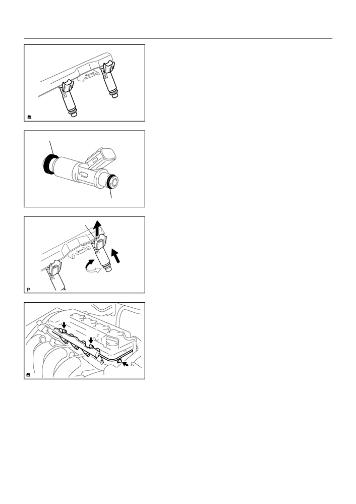
4.
DISCONNECT ENGINE WIRE
(a) Disconnect the 4 fuel injector connectors.
(b) Remove the 3 wire harness clamps from the clamp brack-
ets.
A65079
5.
REMOVE EFI FUEL PIPE CLAMP
(a) Remove the EFI fuel pipe clamp.
A65080

11-11
FUEL
- FUEL INJECTOR ASSY
6.
DISCONNECT FUEL TUBE SUB-ASSY
(a) Using a SST, disconnect the fuel tube.
Retainer
SST
09268-21010
(at 4 places)
(1)
Assemble the SST to the connection as shown.
(2)
Turn the SST, align the retainers inside the connec-
tor with the SST chamfered parts and insert the SST
into the connector.
(3)
Slide the SST and the connector together towards
Turn
the fuel tube assembly.
NOTICE:
SST
F
Check if there is dirt mud on the pipe and around the
connector before disconnecting them and clean the
dirt away.
Insert
F
Do not bent, fold and rotate the nylon tube.
F
When the connector and the pipe are stuck, push and
pull the connector to free to disconnect and
pull it out.
F
Prevent the disconnected pipe and connector from
damaging and mixing foreign objects by covering
A65081
them with a vinyl bag.
Retainer
O-ring
Pipe
Nylon Tube
Housing
A65082
7.
REMOVE FUEL DELIVERY PIPE SUB-ASSY
(a) Remove the 3 bolts and fuel delivery pipe together with
the 4 fuel injectors.
NOTICE:
Be careful not to drop the fuel injectors when removing the
fuel delivery pipe.
A65083
(b) Remove the 2 spacers from the cylinder head.
A65084
11-12
FUEL
- FUEL INJECTOR ASSY
8.
REMOVE FUEL INJECTOR ASSY
(a) Pull out the 4 fuel injectors from the fuel delivery pipe.
A65085
9.
INSTALL FUEL INJECTOR ASSY
New Insulator
(a) Install a new insulator to the each fuel injector.
(b) Apply a light coat of spindle oil or gasoline to a new O-
ring, and install it to the each fuel injector.
NOTICE:
Never use engine, gear or brake oil.
Apply a light coat of gasoline
A60598
(c)
Apply a light coat of spindle oil or gasoline on the place
Connector
Upward
where the fuel delivery pipe touches on the O-ring.
(d) While turning the fuel injector clockwise and counter-
clockwise, and push it to the fuel delivery pipe.
NOTICE:
F
Be careful not twist the O-ring.
Push
F
After installing the fuel injectors, Check that they
Turn
turns smoothly. If the fuel injector does not, reinstall
A60600
it with a new O-ring.
10. INSTALL FUEL DELIVERY PIPE SUB-ASSY
(a) Install the 2 spacers to the cylinder head.
A
(b) Install the fuel delivery pipe together with the 4 fuel injec-
tors with the 3 bolts.
A
Torque:
Bolt A 19 N m (194 kgf cm, 14 ft lbf)
Bolt B 9.0 N m (92 kgf cm, 80 in. lbf)
NOTICE:
B
A65083
F
Be careful not drop the fuel injectors when installing
the fuel delivery pipe.
F
Check that the fuel injectors rotate smoothly after
installing the fuel delivery pipe.
11.
CONNECT FUEL TUBE SUB-ASSY
(a)
Connect the fuel tube to the fuel delivery pipe.
NOTICE:
F
Check if there is any damage or foreign objects on the connected part of the fuel tube.
F
After connecting, check if the fuel tube and the connector are securely connected by pulling
them.
11-13
FUEL
-
FUEL INJECTOR ASSY
12. INSTALL CYLINDER HEAD COVER NO.2
(a) Install the cylinder head cover with the 2 nuts and 2 clips.
Torque: 7.0 N m (71 kgf cm, 62 in. lbf)
13. CHECK FUEL LEAK (See page 11-1)

11-14
FUEL
- FUEL PUMP ASSY
FUEL PUMP ASSY
110FK-01
COMPONENTS
Rear Seat Cushion Assy
Rear Floor Service Hole Cover
Fuel Tank Main Tube Sub-assy
6.0 (61, 53 in. lbf)
Fuel Evaporation Tube Sub-assy No 2
X8
Fuel Tank Vent Tube Set Plate
Tube Joint Clip
Fuel Pump Assembly
F Gasket
N·m (kgf·cm, ft·lbf)
: Specified torque
F Non-reusable part
A65087

11-15
FUEL
- FUEL PUMP ASSY
Vapor Pressure Sensor Assy
Tube Joint Clip
Fuel Pump Harness
Fuel Suction Plate Sub-assy
Fuel Filter
Fuel Sender Gauge Assy
Fuel Pump Assy
F O-ring
Fuel Pressure Regulator Assy
Fuel Pump Filter
F Clip
Fuel Pump Cushion Rubber
Fuel Suction Support No. 2
F Non-reusable part
A65021

11-16
FUEL
- FUEL PUMP ASSY
110FL-01
Removal & Installation and Disassembly & Reassembly
1.
REMOVE BENCH TYPE REAR SEAT CUSHION ASSY (See page 72-6, 72-8)
2.
REMOVE REAR FLOOR SERVICE HOLE COVER
(a) Remove the rear service hole cover.
Butyl Tape
A65023
(b) Disconnect the fuel pump and vapor pressure sensor
connector.
A65088
3.
WORK FOR PREVENTING GASOLINE FROM SPILLING OUT
(a) Start the engine.
(b) After the engine has stopped on the its own, turn the ignition switch to lock.
4.
DISCONNECT FUEL TANK MAIN TUBE SUB-ASSY
(a) Remove the tube joint clip, and pull out the fuel tank main
tube.
NOTICE:
F
Check if there is any dirt like mud around the fuel tube
joint before this work and clean dirt away.
F
Be careful of dirt like mud because the fuel tube joint
has an O-ring to seal the fuel tube joint and fuel suc-
A65024
tion plate.
F
Do not use any tool in this work.
F
Do not bend or twist the nylon tube by force.
Fuel Tube Joint
Nylon Tube
F
After disconnecting, cover the fuel t ube joint with a vi-
nyl bag.
F
When the fuel tube joint and fuel suction plate are
stuck, pinch the fuel tank main tube between fingers,
O-ring
Tube Joint Clip
and turn it carefully to free and then disconnect the
fuel tank main tube.
Fuel Suction Plate
A60575