Toyota Corolla (2004+). Manual - part 89

12-1
EMISSION CONTROL
- EMISSION CONTROL SYSTEM
EMISSION CONTROL SYSTEM
1204D-01
ON-VEHICLE INSPECTION
1.
INSPECT AIR-FUEL RATIO COMPENSATION SYS-
TEM
HINT:
You can also check the system by choosing ”DATA MONITOR”,
then ”O2 SENSOR OUTPUT VOLTAGE” on the monitor of the
hand-held tester.
(a) Connect the hand-held tester to the terminal 23 (OX1A)
7 (E1) and 21 (OX1B) 7 (E1) of the ECM.
CAUTION:
Connect test l eads from the back side of the connector with
the ECU connected.
E1
OX1B
(b) Warm up the oxygen sensor with the engine speed at
2,500 rpm for approx. 2 minutes.
(c)
Confirm that the voltage changes between 0V to 1V with
the engine speed at 2,500 rpm.
OK:
The voltage changes more than 8 times in 10 se-
conds.
CAUTION:
OX1A
A65749
F
Perform the check immediately after the end of the
warming up.
F
If not confirming the change of voltage, warming up
the oxygen sensor again.
2.
INSPECT FUEL CUT OFF RPM
(a)
Increase the engine speed to at least 3,500 rpm.
(b)
Use a sound scope to check for injector operating noise.
(c)
Check that when the throttle lever is released, injector operation noise stops momentarily and then
resumes.
3.
INSPECT EVAPORATIVE EMISSION CONTROL SYS-
TEM
(a) After starting the engine, disconnect the vacuum hose
shown in the illustration.
(b) Confirm vacuum occurs at the vsv port, when choosing
”ACTIVE TEST” and ”PURGE VSV” according to the dis-
play on hand-held tester.
(c)
Finish ”ACTIVE TEST”, then connect the vacuum hose
A65936
again.
(d) After going to ”ECM DATA MONITOR” on the hand-held
tester, choose ”PURGE VSV” to check the operation of
the purge VSV.
(e) After warm up the engine and drive the vehicle, confirm
the VSV turns on from off.

12-2
EMISSION CONTROL
- EMISSION CONTROL SYSTEM
4.
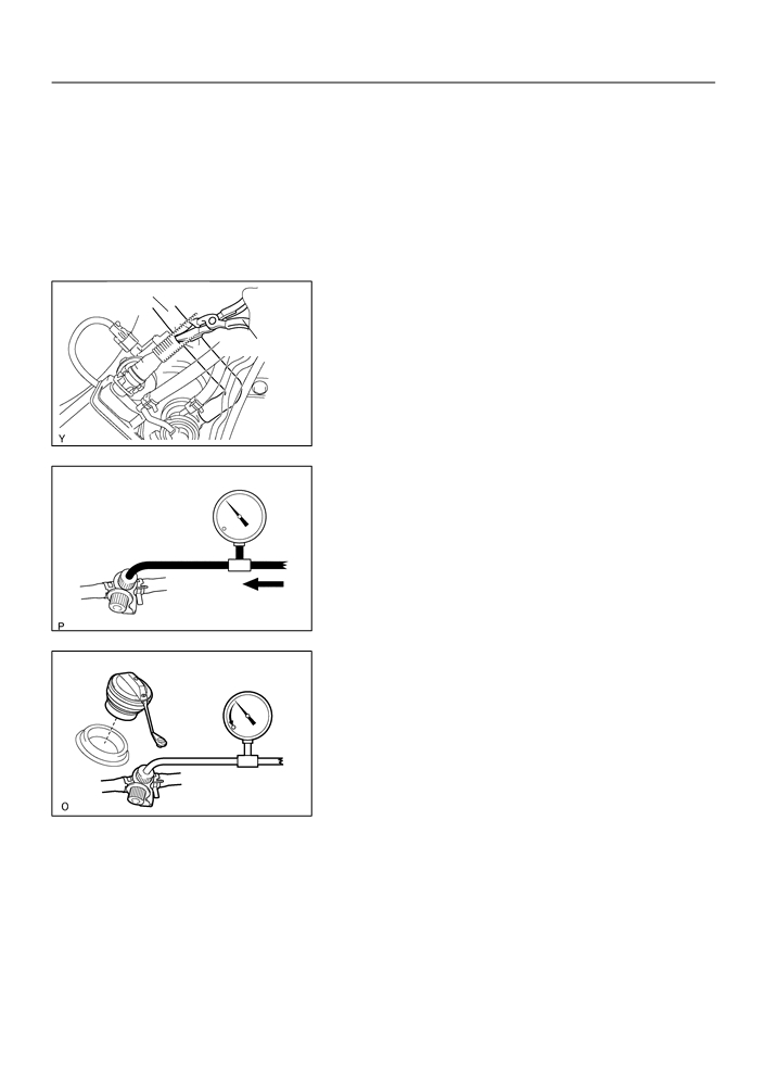
INSPECT EVAP SYSTEM LINE
Vacuum Gauge
(a) Warm up the engine and stop the engine. Allow the en-
gine to warm up to normal operating temperature.
(b) Install a vacuum gauge (EVAP control system test equip-
ment vacuum gauge) to the EVAP service port on the
purge line.
B06544
(c)
TOYOTA Hand-Held Tester:
Forced driving of the VSV for the EVAP.
(1)
Connect a TOYOTA hand-held tester to the DLC3
(2)
Start the engine.
(3)
Push the TOYOTA hand-held tester main switch
ON.
(4)
Use the ACTIVE TEST mode on the TOYOTA
hand-held tester to operate the VSV for the EVAP.
(d) If you have no TOYOTA Hand-Held Tester:
Forced driving of the VSV for the EVAP.
(1)
Disconnect the VSV connector for the EVAP.
(2)
Connect the positive (+) and negative (-) leads from
the battery to the VSV terminals for the EVAP.
(3)
Start the engine.
Battery
A65906
(e) Check the vacuum at idle
Vacuum Gauge
Vacuum:
Maintain at 0.368 - 19.713 in.Hg (5 -268 in.Aq) for over
5 seconds.
HINT:
If the vacuum does not change, you can conclude that the hose
connecting the VSV to the service port has come loose or is
blocked, or the VSV is malfunctioning.
B06545
(f)
TOYOTA Hand-Held Tester:
Conclude forced driving of the VSV for the EVAP.
(1)
Stop the engine.
(2)
Disconnect the TOYOTA hand-held tester from the
DLC3.
(g) If you have no TOYOTA Hand-Held tester:
Conclude forced driving of the VSV for the EVAP.
(1)
Stop the engine.
12-3
EMISSION CONTROL
- EMISSION CONTROL SYSTEM
(2)
Disconnect the positive (+) and negative (-) leads
from the battery from the VSV terminals for the
EVAP.
(3)
Connect the VSV connector for the EVAP.
(h) Disconnect the vacuum gauge from the EVAP service
port on the purge line.
(i)
Connect a pressure gauge to the EVAP service port on
the purge line.
Air Drain Hose
(j)
Check the pressure.
(1)
Close off the air drain hose at the marked position
of the canister with a hose clipper or similar instru-
ment.
Hose Clipper
A63957
(2)
Add the pressure (13.5 - 15.5 in. Aq) from the EVAP
service port.
Pressure Gauge
Pressure:
2 minutes after the pressure is added, the gauge
should be over 7.7-8.8 in.Aq.
HINT:
If you can not add pressure, you can conclude that the hose
Pressure
connecting the VSV - canister - fuel tank has slipped off or the
B06546
VSV is open.
(3)
Check if the pressure decreases when the fuel tank
cap is removed while adding pressure.
HINT:
If the pressure dose not decrease when the filler cap is re-
moved, then you can conclude that the hose connecting the
service port to the fuel tank is blocked, etc.
(k)
Disconnect the pressure gauge from the EVAP service
port on the purge line.
A52634

12-4
EMISSION CONTROL
- EMISSION CONTROL SYSTEM
5.
CHECK AIRTIGHTNESS IN FUEL TANK AND FILLER
EVAP Line Hose
PIPE
(a) Disconnect the EVAP line hose from the charcoal canis-
ter.
(1)
Pinch portion A.
(2)
Pull out the connector.
(b) Pressurize and make the internal pressure in the fuel tank
4 kPa (41 gf/cm2, 0.58 psi).
(c)
Check that the internal pressure of the fuel tank can be
hold for 1 minute.
(d) Check the connected portions of each hose and pipe.
A
(e) Check the installed parts on the fuel tank.
If there is no abnormality, replace the fuel tank and filler pipe.
(f)
Reconnect the EVAP line hose to the charcoal canister.
A65905
6.
INSPECT FUEL CUT OFF VALVE AND FILL CHECK
VALVE
(a) Disconnect the purge line hose and EVAP line hose from
the charcoal canister.
(b) Plug the cap to the air drain hose.
Air
(c)
Pressurize 4 kPa (41 gf/cm2, 0.58 psi) to the purge port
and check that there is ventilation through the EVAP line
hose.
Purge Line Hose
EVAP Line Hose
HINT:
A63960
In the condition that the fuel is full, as the float value of the fill
check valve is closed and has no ventilation, it is necessary to
check the fuel amount (volume).
(d) Check if there is anything struck in the vent line hose and
EVAP line hose.
If there is no stuck in hoses, replace the fuel cut off valve and
fill check valve.
(e) Reconnect the purge line hose and EVAP line hose to the
charcoal canister.
7.
CHECK AIR INLET LINE
Air Inlet
(a) Disconnect the air inlet line hose from the charcoal canis-
Line Hose
ter.
(b) Check that there is ventilation in the air inlet line.
(c)
Reconnect the air inlet line hose to the charcoal canister.
Air
A63962

12-5
EMISSION CONTROL
- EMISSION CONTROL SYSTEM
8.
VISUALLY INSPECT HOSES, CONNECTIONS AND
GASKETS
(a) Check for cracks, leaks or damage.
HINT:
Separation of the engine oil dipstick, oil filler cap, PCV hose,
etc. may cause the engine to run out of turn. Disconnection,
looseness or cracks in the parts of the air induction system be-
tween the throttle body and cylinder head will allow air suction
A65907
and cause the engine to run out of turn.
9.
INSPECT HEATER RESISTANCE OF HEATED OXY-
GEN SENSOR
(a) Disconnect the oxygen sensor connector.
+B
HT
(b) Using an ohmmeter, measure the resistance between the
terminals HT and +B.
Resistance: 11 - 16
W at 20_C (68_F)
A60559
10. INSPECT FUEL TANK CAP
(a) Visually check if the cap and/or gasket are deformed or
damaged.
Gasket
B11870

14-93
ENGINE MECHANICAL
- CAMSHAFT
CAMSHAFT
140OI-01
COMPONENTS
Fan and Generator V Belt
7.0 (71, 62 in. lbf)
Clip
Cylinder Head Cover No. 2
52 (530, 38)
Engine Mounting Insulator RH
52 (530, 38)
Clip
Engine Under Cover RH
N·m (kgf·cm, ft·lbf)
: Specified torque
A64044

14-94
ENGINE MECHANICAL
- CAMSHAFT
9.0 (92, 80 in. lbf)
9.0 (92, 80 in. lbf)
Engine Wire
9.0 (92, 80 in. lbf)
Ignition Coil Assy
Ventilation Hose No. 2
9.0 (92, 80 in. lbf)
11 (112, 8)
Seal Washer
11 (112, 8)
11 (112, 8)
Clamp Bracket
Clamp Bracket
11 (112, 8)
Ventilation Hose
Clamp Bracket
Cylinder Head Cover
Sub-assy
Gasket
N·m (kgf·cm, ft·lbf)
: Specified torque
A64043

14-95
ENGINE MECHANICAL
- CAMSHAFT
Camshaft Bearing Cap No. 3
13 (133, 10)
23 (235, 17)
Camshaft Bearing Cap No. 1
Camshaft No. 2
Camshaft Timing Gear
Camshaft
or Sprocket
54 (551, 40)
Camshaft Timing Gear Assy
54 (551, 40)
9.0 (92, 80 in. lbf)
Chain Tensioner
Assy No. 1
Timing Chain Sub-assy
29 (296, 21)
69 (704, 51)
V-ribbed Belt
Tensioner Assy
N·m (kgf·cm, ft·lbf)
: Specified torque
A64006

14-96
ENGINE MECHANICAL
- CAMSHAFT
140OJ-01
REPLACEMENT
1.
REMOVE ENGINE UNDER COVER RH
2.
REMOVE CYLINDER HEAD COVER NO.2
(a) Remove the 2 screw, 3 clips and engine under cover.
A65077
3.
REMOVE FAN AND GENERATOR V BELT
(a) Turn the V-ribbed belt tensioner slowly clockwise and
loosen it. Then, remove the fan and generator V belt and
put back the V-ribbed belt tensioner little by little and fix
it quietly.
A60622
4.
REMOVE ENGINE MOUNTING INSULATOR
SUB-ASSY RH
(a) Remove the PS oil pump reservoir and put it aside.
(b) Place a wooden block between the jack and engine, and
set the jack, then remove the 4 bolts, the 2 nuts and en-
gine mounting insulator RH.
A01045
A64005

14-97
ENGINE MECHANICAL
- CAMSHAFT
5.
DISCONNECT ENGINE WIRE
(a) Remove the 5 clamps from the 5 clamp brackets.
(b) Disconnect the 4 ignition coil connectors.
A64021
(c)
Remove the bolt and nut installing the engine wire.
A64022
6.
REMOVE IGNITION COIL ASSY
(a) Remove the 4 bolts and 4 ignition coils.
A64023
7.
DISCONNECT VENTILATION HOSE
(a) Disconnect the ventilation hose from the cylinder head
cover.
A65078
8.
DISCONNECT VENTILATION HOSE NO.2
(a) Disconnect the ventilation hose from the cylinder head
cover.
A64058

14-98
ENGINE MECHANICAL
- CAMSHAFT
9.
REMOVE CYLINDER HEAD COVER SUB-ASSY
(a) Remove the 9 bolts, 2 seal washers, 2 nuts, 3 clamp
brackets and cylinder head cover.
A64856
10. SET NO. 1 CYLINDER TO TDC/COMPRESSION
Mark
(a) Turn the crankshaft pulley, and align its groove with timing
Mark
mark ”0” of the timing chain cover.
(b) Check that the point marks of the camshaft timing sprock-
et and VVT timing sprocket are in straight line on the tim-
ing chain cover surface as shown in the illustration.
HINT:
If not, turn the crankshaft 1 revolution (360_) and align the
Mark
marks as above.
Timing Chain
Cover Surface
Groove
A62185
11. REMOVE V-RIBBED BELT TENSIONER ASSY
(a) Remove the bolt, nut and V-ribbed belt tensioner.
HINT:
Handle a jack up and down to remove the bolt.
A11858
12. REMOVE CAMSHAFT
NOTICE:
Be sure not to revolve the crankshaft without the chain ten-
sioner.
(a) Set the No. 1 cylinder to the TDC/compression.
(b) Place match marks on the timing chain and camshaft tim-
Paint Mark
ing sprockets.
A62186
14-99
ENGINE MECHANICAL
- CAMSHAFT
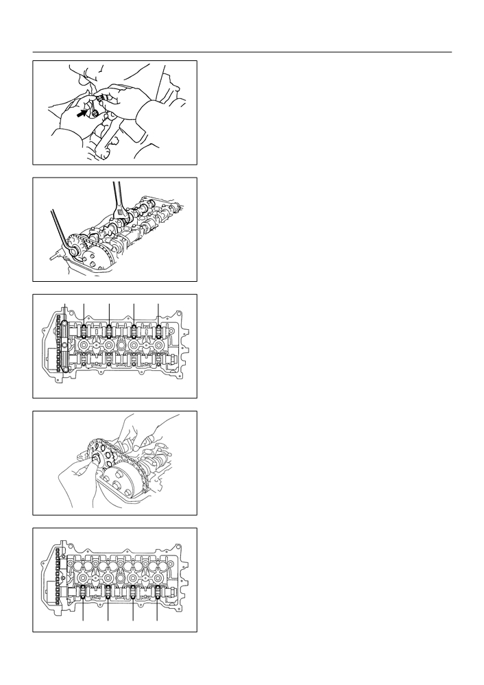
(c)
Remove the 2 nuts and chain tensioner.
Push
A62178
(d) Fix the camshaft with a wrench and so on, then loosen
Fix
the camshaft timing gear set bolt.
Tighten
NOTICE:
Be careful not to damage the valve lifter.
A62187
2
4
5
3
1
(e) Loosen the camshaft bearing cap bolts on No. 2 camshaft
in the order as shown in the illustration in several
passes,and remove the caps.
A62188
(f)
Remove the camshaft timing gear as shown in the illustra-
tion.
A32124
(g) Loosen the camshaft bearing cap bolts on camshaft in the
order as shown in the illustration in several passes,and
remove the caps.
2
4
3
1
A62189

14-100
ENGINE MECHANICAL
- CAMSHAFT
(h) Remove the camshaft with holding the timing chain.
A32125
(i)
Tie the timing chain with a string as shown in the illustra-
tion.
NOTICE:
Be careful not to drop anything inside the timing chain cov-
er.
A32556
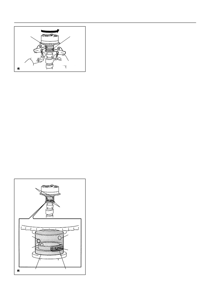
13. INSPECT CAMSHAFT TIMING GEAR ASSY
Retard Side
(a) Check the lock of camshaft timing gear.
Path
(1)
Grip the camshaft with a vice, and confirm the cam-
shaft timing gear is locked.
NOTICE:
Advance
Be careful not to damage the camshaft.
Side Path
(b) Release lock pin.
(1)
Cover 4 oil paths of cam journal with vinyl tape as
shown in the illustration.
HINT:
Two advance side paths are provided in the groove of the cam-
Open
Close
shaft. Plug one of the path with a rubber piece.
(2)
Break through the tapes of the advance side path
and the retard side path on the opposite side of the
Open
Close
groove.
Vinyl Tape
Rubber
A62190
(3)
Put air pressure into two broken paths (the advance
Retard
Advanced
side path and the retard side path) with about 150
Side Path
Side Path
kPa {1.5 kgfcm}.
CAUTION:
Cover the pathes with shop rag to avoid oil splashing.
A62191
14-101
ENGINE MECHANICAL
- CAMSHAFT
(4)
Confirm if the camshaft timing gear assembly re-
Retard
Advanced
volves in the timing advance direction when weak-
Side Path
Side Path
ening the air pressure of the timing retard path.
HINT:
The lock pin is released, and camshaft timing gear, revolves in
the advance direction.
Decompress
Hold Pressure
A62192
(5)
When the camshaft timing gear comes to the most
advanced position, take out the air pressure of the
timing retard side path, and then, take out that of
timing advance side path.
CAUTION:
Camshaft timing assembly gear occasionally shifts to the
retard side abruptly, if the air compression of the advanced
side path is released before retard side path. It often
causes the breakage of the lock pin.
(c)
Check smooth revolution
(1)
Revolve the camshaft timing gear assembly within
the movable range except for the most retarded
position several times, and check the smooth revo-
lution.
CAUTION:
Be sure to perform this check by hand, instead of air pres-
sure.
(d) Check the lock in the most retarded position.
(1)
Confirm that the camshaft timing gear assembly is
locked at the most retarded position.
14. REMOVE CAMSHAFT TIMING GEAR ASSY
Retard Side
(a) Grip the camshaft with a vice, and confirm that it the gear
Path
locked.
CAUTION:
Be careful not to damage the camshaft.
Advance
(b) Cover 4 oil paths of cam journal with vinyl tape as shown
Side Path
in the illustration.
HINT:
Two advance side paths are provided in the groove of the cam-
shaft. Plug one of the path with a rubber piece.
(c)
Break through the tapes of the advance side path and the
Open
Close
retard side path on the opposite side of the groove.
Open
Close
Vinyl Tape
Rubber
A62190

14-102
ENGINE MECHANICAL
- CAMSHAFT
(d) Put air pressure into two broken paths (the advance side
Retard
Advanced
path and the retard side path) with about 150 kPa {1.5
Side Path
Side Path
kgfcm}.
CAUTION:
Cover the pathes with shop rag to avoid oil splashing.
A62191
(e) Confirm if the camshaft timing gear assembly revolves in
Retard
Advanced
the timing advance direction when weakening the air
Side Path
Side Path
pressure of the timing retard path.
HINT:
The lock pin is released, and camshaft timing gear revolves in
the advance direction.
Decompress
(f)
When the camshaft timing gear comes to the most ad-
Hold Pressure
vanced position, take out the air pressure of the timing re-
A62192
tard side path, and then, takeout that of timing advance
side path.
CAUTION:
Camshaft timing gear assembly occasionally shifts to the
retard side abruptly, if the air compression of the advanced
side path is released before retard side paths. It often
causes the breakage of the lock pin.
(g) Remove the fringe bolt of camshaft timing gear assembly.
NOTICE:
F
Be sure not to remove the other 4 bolts.
Fringe Bolt
F
In case of reusing the camshaft timing gear, release
the strait pin locking first, and then install the gear.
Straight Pin
A62193
15. INSTALL CAMSHAFT TIMING GEAR ASSY
Straight Pin
(a) Put the camshaft timing gear assembly and the camshaft
together with the straight pin off the key groove.
(b) Turn the camshaft timing gear assembly to the left direc-
tion (as shown in the illustration) with pushing it lightly
against the camshaft. Push further at the position where
the pin gets into the groove.
CAUTION:
Key Groove
A62194
Be sure not to turn the camshaft timing gear to the retard
angle side (to the right angle).
(c)
Check that there is no clearance between the gear’s
fringe and the camshaft.
(d) Tighten the fringe bolt with the camshaft timing gear fixed.
Torque: 54 N m (551 kgf cm 40 ft lbf)