Toyota Corolla (2004+). Manual - part 62

05-151
DIAGNOSTICS
-
SFI SYSTEM (April, 2003)
MONITOR STRATEGY
P0300
Random/Multiple cylinder misfire detected
P0301
Cylinder 1 misfire detected
Related DTCs
P0302
Cylinder 2 misfire detected
P0303
Cylinder 3 misfire detected
P0304
Cylinder 4 misfire detected
Main sensors
Camshaft position sensor, crankshaft position sensor
Required sensors/components
Engine coolant temperature sensor, intake air temperature sensor,
Related sensors
throttle position sensor
Frequency of operation
Continuous
Every 1,000 revolutions (soon after engine is started: 1 time, other 4 times) (emission related misfire)
Duration
Every 200 revolutions (1 or 3 times) (catalyst deteriorating misfire)
2 driving cycles MIL ON
MIL operation
Immediate MIL blinking (Catalyst deteriorating misfire)
Sequence of operation
None
TYPICAL ENABLING CONDITIONS
Specification
Item
Minimum
Maximum
The monitor will run whenever the follow-
See ”List of Disable a Monitor” (On page 05-25)
ing DTCs are not present
Battery voltage
8 V
-
VVT
Normal operation (i. e. not under scan-tool control)
Engine speed fluctuation
Engine speed should not have changed rapidly
Engine speed (Two full revolutions (2 rev.)
6,700 rpm (AT)
450 rpm
after engine has started)
6,600 rpm (MT)
Engine coolant temperature
-10_C (14_F)
-
Intake air temperature
-10_C (14_F)
-
Intake air amount per revolution (varies
0.14 g/rev
-
with engine speed)
Throttle position learning
Completed
Rapid throttle opening or closing operation has not occurred
Throttle position
Changing value of throttle position
-
greater than 0.5_ per 0.008 seconds
Transient spark retard
(The spark timing delay control in a short
Not commanded
time for preventing surge at the time of a
sudden acceleration.)
10 times/1,000 revolutions
Rough road counter
-
(not running on rough road)
TYPICAL MALFUNCTION THRESHOLDS
Detection Criteria
Threshold
Emission related misfire rate:
1. During the first 1,000 revolutions after engine start
(1 time will set MIL)
1.44 % per 1,000 revolutions
2. After the first 1,000 revolutions have occurred
(4 times will set MIL)
Catalyst damage misfire count:
1. Low engine rpm area (ex. less than 3,000 rpm):
75 count per 200 revolutions
200 rev. (3 times to set MIL)
(threshold varies with engine speed, intake air amount per revolution)
2. High engine rpm area: Every 200 revolutions

05-152
DIAGNOSTICS
- SFI SYSTEM (April, 2003)
WIRING DIAGRAM
Refer to DTC P0351 on page 05-177 for the wiring diagram of the ignition system.
ECM
I6 Injector No. 1
1
B-W
Y
#10
E3
From
1
2
Terminal 6
I7 Injector No. 2
2
of Ignition
B-W
B-W
B
#20
E3
Switch
1
2
B-W
I8 Injector No. 3
3
B-W
W
#30
E3
1
2
I9 Injector No. 4
4
B-W
L
#40
E3
1
2
A84874
CONFIRMATION DRIVING PATTERN
(a) Connect the hand-held tester or the OBD II scan tool to the DLC3.
(b) Record DTCs and the freeze frame data.
(c)
Set the check mode using the hand-held tester (See page 05-11).
(d) Read the value on the misfire counter for each cylinder when idling. If the value is displayed on the
misfire counter, skip the following procedure of confirmation driving.
(e) Drive the vehicle several times with the engine speed, load and its surrounding range shown with EN-
GINE SPD, CALC LOAD in the freeze frame data or MISFIRE RPM, MISFIRE LOAD in the data list.
If you have no hand-held tester, turn the ignition switch OFF after the symptom is simulated once. Then re-
peat the simulation process again.
HINT:
Do not turn the ignition switch OFF during the confirmation driving pattern. This switches the diagnosis sys-
tem from the check mode to the normal mode, so all the DTCs and freeze frame data will be erased.
Engine Speed
Time
Idling
3 minutes and 30 seconds or more
1,000 rpm
3 minutes or more
2,000 rpm
1 minute and 30 seconds or more
3,000 rpm
1 minute or more
(f)
Check whether there is misfire or not by monitoring DTC and the freeze frame data. After that, record
them.
(g) Turn the ignition switch OFF and wait for at least 5 seconds.

05-153
DIAGNOSTICS
-
SFI SYSTEM (April, 2003)
INSPECTION PROCEDURE
HINT:
F
If DTCs besides misfire are memorized simultaneously, first perform the troubleshooting for them.
F
Read freeze frame data using the hand−held tester or the OBD II scan tool. Freeze frame data records
the engine conditions when a malfunction is detected. When troubleshooting, it is useful for determin-
ing whether the vehicle was running or stopped, the engine was warmed up or not, the air-fuel ratio
was lean or rich, etc. at the time of the malfunction.
F
If the misfire does not occur when the vehicle is brought to the workshop, the misfire can be confirmed
by reproducing the condition of the freeze frame data. After finishing the repair, confirm that there is
no misfire (See confirmation driving pattern).
F
When either of SHORT FT #1 or LONG FT #1 in the freeze frame data is over the range of ±20 %,
there is a possibility that the air-fuel ratio is inclining either to RICH (-20 % or less) or LEAN (+20 %
or more).
F
When COOLANT TEMP in the freeze frame data is less than 80°C (176°F), there is a possibility of
misfire only during engine warm up.
F
If the misfire cannot be reproduced, the reason may be because of the driving the vehicle with lack
of fuel, the use of improper fuel, a stain on the ignition plug, etc.
F
Be sure to check the value on the misfire counter after the repair.
1
CHECK OTHER DTC OUTPUT(IN ADDITION TO MISFIRE DTCS)
(a)
Connect the hand-held tester or the OBD II scan tool to the DLC3.
(b)
Turn the ignition switch ON and push the hand-held tester or the OBD II scan tool main switch ON.
(c)
Select the item ”DIAGNOSIS / ENHANCED OBD II / DTC INFO / CURRENT CODES”.
(d)
Read the DTCs.
Result:
Display (DTC output)
Proceed to
”P0300, P0301, P0302, P0303 and/or P0304”
A
”P0300, P0301, P0302, P0303 and/or P0304” and other DTCs
B
HINT:
If any other codes besides P0300, P0301, P0302, P0303 or P0304 are output, perform the troubleshooting
for those DTCs first.
B
GO TO RELEVANT DTC CHART
(See page 05-35)
A
2
CHECK WIRE HARNESS, CONNECTOR AND VACUUM HOSE IN ENGINE ROOM
(a) Check the connection conditions of the wire harness and connector.
(b) Check the vacuum hose piping for disconnection and break.
NG REPAIR OR REPLACE, THEN CONFIRM THAT
THERE IS NO MISFIRE
OK

05-154
DIAGNOSTICS
- SFI SYSTEM (April, 2003)
3
CHECK CONNECTION OF PCV HOSE
NG REPAIR OR REPLACE PCV HOSE
OK
4
READ VALUE OF HAND-HELD TESTER OR OBD II SCAN TOOL(NUMBER OF
MISFIRE)
(a) Connect the hand-held tester or the OBD II scan tool to the DLC3.
(b) Turn the ignition switch ON and push the hand-held tester or the OBD II scan tool main switch ON.
(c)
Start the engine.
(d) Select the item ”DIAGNOSIS / ENHANCED OBD II / DATA LIST / ALL / CYL#1 - CYL#4”.
(e) Read the number of misfire on the hand-held tester or the OBD II scan tool.
HINT:
When a misfire is not reproduced, be sure to branch below based on the stored DTC.
Result:
High Misfire Rate Cylinder
Proceed to
1 or 2 cylinders
A
More than 3 cylinders
B
B
Go to step 15
A
05-155
DIAGNOSTICS
- SFI SYSTEM (April, 2003)
5
CHECK SPARK PLUG AND SPARK OF MISFIRING CYLINDER
(a) Remove the ignition coil assembly.
(b) Remove the spark plug.
(c)
Check the spark plug type.
Recommended spark plug:
DENSO made
SK16R11
NGK made
IFR5A11
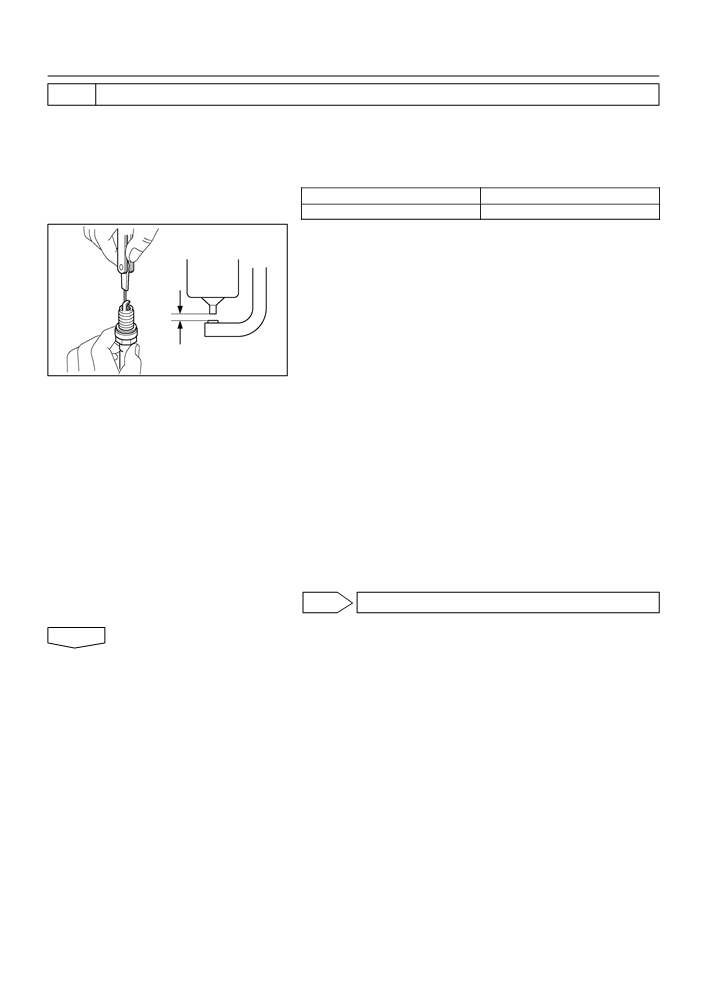
(d) Check the spark plug electrode gap.
Electrode gap: 1.0 to 1.3 mm (0.039 to 0.051 in.)
NOTICE:
If adjusting the gap of a new spark plug, bend only the base
of the ground electrode. Do not touch the tip. Never attempt
to adjust the gap on a used plug.
(e) Check the electrode for carbon deposits.
1.0 to 1.3 mm
(f)
Perform a spark test.
(0.039 to 0.051 in.)
B02101
CAUTION:
Absolutely disconnect the each injector connectors.
NOTICE:
Do not crank the engine for more than 5 seconds at a time.
(1)
Install the spark plug to the ignition coil, and connect
the ignition coil connector.
(2)
Disconnect the injector connector.
(3)
Ground the spark plug.
(4)
Check if spark occurs while the engine is being
cranked.
Standard: Spark jumps across electrode gap.
(g) Reinstall the spark plug.
(h) Reinstall the ignition coil assy.
OK Go to step 8
NG

05-156
DIAGNOSTICS
- SFI SYSTEM (April, 2003)
6
CHANGE NORMAL SPARK PLUG AND CHECK SPARK OF MISFIRING CYLINDER
(a) Change to the normal spark plug.
(b) Perform a spark test.
CAUTION:
Absolutely disconnect each injector connector.
NOTICE:
Do not crank the engine for more than 5 seconds at a time.
(1)
Install the spark plug to the ignition coil, and connect the ignition coil connector.
(2)
Disconnect the injector connector.
(3)
Ground the spark plug.
(4)
Check if spark occurs while the engine is being cranked.
Standard: Spark jumps across electrode gap.
OK REPLACE SPARK PLUG
NG

05-157
DIAGNOSTICS
- SFI SYSTEM (April, 2003)
7
CHECK HARNESS AND CONNECTOR OF MISFIRING CYLINDER(IGNITION COIL -
ECM)
(a)
Check the harness and connector between the ignition
coil and ECM (IGF terminal) connectors
E3
(1)
Disconnect the I2, I3, I4 or I5 ignition coil and igniter
connector.
(2)
Disconnect the ECM E3 connector.
(3)
Check the resistance between the wire harness
side connectors.
IGF
Standard (Check for open):
ECM Connector
A65743
Tester Connection
Specified Condition
IGF (I2-2) - IGF (E3-23)
Wire Harness Side:
IGF (I3-2) - IGF (E3-23)
Below 1 W
I2
I3
I4
I5
IGF (I4-2) - IGF (E3-23)
Ignition Coil and Igniter Connector
IGF (I5-2) - IGF (E3-23)
Standard (Check for short):
Tester Connection
Specified Condition
IGF (I2-2) or IGF (E3-23) - Body ground
IGF (I3-2) or IGF (E3-23) - Body ground
10 kW or higher
IGF
IGF (I4-2) or IGF (E3-23) - Body ground
Front View
IGF (I5-2) or IGF (E3-23) - Body ground
A54393
(4)
Reconnect the ECM connector.
(5)
Reconnect the ignition coil and igniter connector.
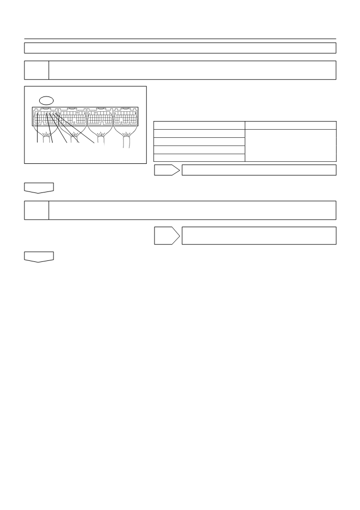
(b)
Check the harness and connector between the ignition
coil and ECM (IGT terminal) connectors
E3
(1)
Disconnect the I2, I3, I4 or I5 ignition coil and igniter
connector.
(2)
Disconnect the ECM E3 connector.
(3)
Check the resistance between the wire harness
side connectors.
IGT4
IGT3
IGT2
IGT1
Standard (Check for open):
ECM Connector
A65743
Tester Connection
Specified Condition
IGT (I2-3) - IGT1 (E3-8)
IGT (I3-3) - IGT2 (E3-9)
Wire Harness Side:
Below 1 W
I2
I3
I4
I5
IGT (I4-3) - IGT3 (E3-10)
Ignition Coil and Igniter Connector
IGT (I5-3) - IGT4 (E3-11)
Standard (Check for short):
Tester Connection
Specified Condition
IGT (I2-3) or IGT1 (E3-8) - Body ground
IGT (I3-3) or IGT2 (E3-9) - Body ground
10 kW or higher
IGT
IGT (I4-3) or IGT3 (E3-10) - Body ground
Front View
IGT (I5-3) or IGT4 (E3-11) - Body ground
A54393
(4)
Reconnect the ECM connector.
(5)
Reconnect the ignition coil and igniter connector.
OK REPLACE IGNITION COIL ASSY (THEN CON-
FIRM THAT THERE IS NO MISFIRE)
NG
05-158
DIAGNOSTICS
- SFI SYSTEM (April, 2003)
REPAIR OR REPLACE HARNESS OR CONNECTOR
8
INSPECT ECM TERMINAL OF MISFIRING CYLINDER(#10, #20, #30 OR #40
VOLTAGE)
(a) Turn the ignition switch ON.
(b) Measure the voltage between the terminals of the E3
E3
ECM connector.
Standard:
Symbols (Terminal No.)
Specified Condition
#10 (E3-1) - E01 (E3-7)
#20 (E3-2) - E01 (E3-7)
E01
#40
#30 #20
#10
8 to 14 V
#30 (E3-3) - E01 (E3-7)
ECM Connector
#40 (E3-4) - E01 (E3-7)
A18294
OK Go to step 11
NG
9
INSPECT FUEL INJECTOR RESISTANCE OF MISFIRING CYLINDER
(See page 11-7)
NG REPLACE FUEL INJECTOR ASSY
(See page 11-10)
OK

05-159
DIAGNOSTICS
- SFI SYSTEM (April, 2003)
10
CHECK HARNESS AND CONNECTOR OF MISFIRING CYLINDER(INJECTOR -
ECM, INJECTOR - IGNITION SWITCH)
(a)
Check the harness and connector between the injector
Wire Harness Side:
connector and ECM connector.
I6
I7
I8
I9
(1)
Disconnect the I6, I7, I8 or I9 injector connector.
Injector Connector
(2)
Disconnect the E3 ECM connector.
(3)
Measure the resistance between the wire harness
side connectors.
1
2
Standard (Check for open):
Tester Connection
Specified Condition
Front View
A84764
Injector (I6-2) - #10 (E3-1)
Injector (I7-2) - #20 (E3-2)
Below 1 W
Injector (I8-2) - #30 (E3-3)
Injector (I9-2) - #40 (E3-4)
E3
Standard (Check for short):
Tester Connection
Specified Condition
Injector (I6-2) or #10 (E3-1) - Body ground
Injector (I7-2) or #20 (E3-2) - Body ground
10 kW or higher
Injector (I8-2) or #30 (E3-3) - Body ground
Injector (I9-2) or #40 (E3-4) - Body ground
#40
#30
#20
#10
ECM Connector
A65743
(4)
Reconnect the ECM connector.
(5)
Reconnect the Iinjector connector.
(b)
Check the harness and connector between the injector
Wire Harness Side:
connector and ignition switch connector.
I10
Ignition Switch Connector
(1)
Disconnect the I6, I7, I8 or I9 injector connector.
(2)
Disconnect the I10 ignition switch connector.
(3)
Measure the resistance between the wire harness
side connectors.
IG2
Standard (Check for open):
Tester Connection
Specified Condition
Front View
A66267
Injector (I6-1) - IG2 (I10-6)
Injector (I7-1) - IG2 (I10-6)
Below 1 W
Injector (I8-1) - IG2 (I10-6)
Injector (I9-1) - IG2 (I10-6)
Standard (Check for short):
Tester Connection
Specified Condition
Injector (I6-1) or IG2 (I10-6) - Body ground
Injector (I7-1) or IG2 (I10-6) - Body ground
10 kW or higher
Injector (I8-1) or IG2 (I10-6) - Body ground
Injector (I9-1) or IG2 (I10-6) - Body ground
(4)
Reconnect the ignition switch connector.
(5)
Reconnect the injector connector.
NG REPAIR OR REPLACE HARNESS OR
CONNECTOR
OK

05-160
DIAGNOSTICS
- SFI SYSTEM (April, 2003)
11
INSPECT FUEL INJECTOR INJECTION AND VOLUME OF MISFIRING CYLINDER
(See page 11-7)
NG REPLACE FUEL INJECTOR ASSY
OK
12
CHECK CYLINDER COMPRESSION PRESSURE OF MISFIRING CYLINDER
(See page 14-1)
NG REPAIR OR REPLACE
OK
13
CHECK VALVE CLEARANCE OF MISFIRING CYLINDER (See page 14-5)
NG ADJUST VALVE CLEARANCE
(See page 14-5)
OK
14
SWITCH STEP BY NUMBER OF MISFIRE CYLINDER(REFER RESULT OF STEP 4)
HINT:
F
If the result of step 4 is ”1 or 2 cylinders” proceed to A.
F
If the result of step 4 is ”more than 3 cylinders” proceed to B.
B
CHECK FOR INTERMITTENT PROBLEMS
(See page 05-41)
A
15
CHECK VALVE TIMING(CHECK FOR LOOSENESS OR A JUMPED TOOTH OF THE
TIMING CHAIN) (See page 14-82)
NG ADJUST VALVE TIMING (See page 14-128)
(REPAIR OR REPLACE TIMING CHAIN)
OK
16
CHECK FUEL PRESSURE (See page 11-5)
NG CHECK AND REPLACE FUEL PUMP,
PRESSURE REGULATOR, FUEL PIPE LINE AND
FILTER
OK

05-161
DIAGNOSTICS
- SFI SYSTEM (April, 2003)
17
READ VALUE OF HAND-HELD TESTER OR OBD II SCAN TOOL(INTAKE AIR
TEMPERATURE AND MASS AIR FLOW RATE)
(a)
Connect the hand-held tester or the OBD II scan tool to the DLC3.
(b)
Turn the ignition switch ON.
(c)
Check the intake air temperature.
(1)
Select the item ”DIAGNOSIS / ENHANCED OBD II / DATA LIST / ALL / INTAKE AIR” and read
its value displayed on the hand-held tester or the OBD II scan tool.
Temperature: Equivalent to ambient temperature
(d)
Check the air flow rate.
(1)
Select the item ”DIAGNOSIS / ENHANCED OBD II / DATA LIST / ALL / MAF” and read its value
displayed on the hand-held tester or the OBD II scan tool.
Standard:
Condition
Air flow rate (gm/s)
Ignition switch ON (do not start engine)
0
Idling
4 to 6
Running without load (2,500 rpm)
13 to 20
From idling to quickly accelerating
Air flow rate fluctuates
NG REPLACE MASS AIR FLOW SENSOR
OK
18
INSPECT ENGINE COOLANT TEMPERATURE SENSOR(RESISTANCE)
(a) Remove the engine coolant temperature sensor.
Ohmmeter
(b) Measure the resistance between the terminals of the en-
gine coolant temperature sensor.
Standard:
Tester Connection
Temperature
Specified Condition
30
20_C (68_F)
2.32 to 2.59 kW
20
1
- 2
80_C (176_F)
0.310 to 0.326 kW
10
NOTICE:
5
Acceptable
If you checking the engine coolant temperature sensor in
3
water, be careful not to allow water to go into the terminals.
2
After checking, dry the sensor.
1
HINT:
0.5
Alternate procedure: Connect an ohmmeter to the installed en-
0.3
gine coolant temperature sensor and read the resistance. Use
0.2
an infrared thermometer to measure the engine temperature in
0.1
the immediate vicinity of the sensor. Compare these values to
the resistance/temperature graph. Change the engine temper-
-20
0
20
40
60
80 100
(-4)
(32)
(68)
(104)
(140)
(176)
(212)
ature (warm up or allow to cool down) and repeat the test.
S01196
S01699
TEMPERATURE _C (_F)
A81700
NG REPLACE ENGINE COOLANT TEMPERATURE
SENSOR
OK

05-162
DIAGNOSTICS
- SFI SYSTEM (April, 2003)
19
SWITCH STEP BY NUMBER OF MISFIRE CYLINDER(REFER RESULT OF STEP 4)
HINT:
F
If the result of step 4 is ”1 or 2 cylinders” proceed to A.
F
If the result of step 4 is ”more than 3 cylinders” proceed to B.
B
AGAIN GO TO STEP 5
A
CHECK FOR INTERMITTENT PROBLEMS (See page 05-41)
05-163
DIAGNOSTICS
- SFI SYSTEM (April, 2003)
05DIN-01
DTC
P0325
KNOCK SENSOR 1 CIRCUIT (BANK 1 OR
SINGLE SENSOR)
DTC
P0327
KNOCK SENSOR 1 CIRCUIT LOW INPUT
(BANK 1 OR SINGLE SENSOR)
DTC
P0328
KNOCK SENSOR 1 CIRCUIT HIGH INPUT
(BANK 1 OR SINGLE SENSOR)
CIRCUIT DESCRIPTION
A flat type knock sensor (non-resonant type) has the structure that can detect the vibration in a wider band
of frequency from about 6 kHz to 15 kHz and has the following features.
Knock sensors are fitted on the cylinder block to detect the engine knocking.
The sensor contains a piezoelectric element which generates a voltage when it becomes deformed, which
occurs when the cylinder block vibrates due to knocking. If engine knocking occurs, the ignition timing is
retarded to suppress it.
DTC No.
DTC Detecting Condition
Trouble Area
F Open or short in knock sensor circuit
Knock sensor signal level remains at low for more than 10
P0325
F Knock sensor (under-torqued or loose)
seconds
F ECM
F Short in knock sensor circuit
P0327
Output voltage of the knock sensor is 0.5 V or less
F Knock sensor
F ECM
F Open in knock sensor circuit
P0328
Output voltage of the knock sensor is 4.5 V or more
F Knock sensor
F ECM
HINT:
If the ECM detects the DTC P0325, it enters the fail-safe mode in which the corrective retarded angle value
is set to the maximum value.
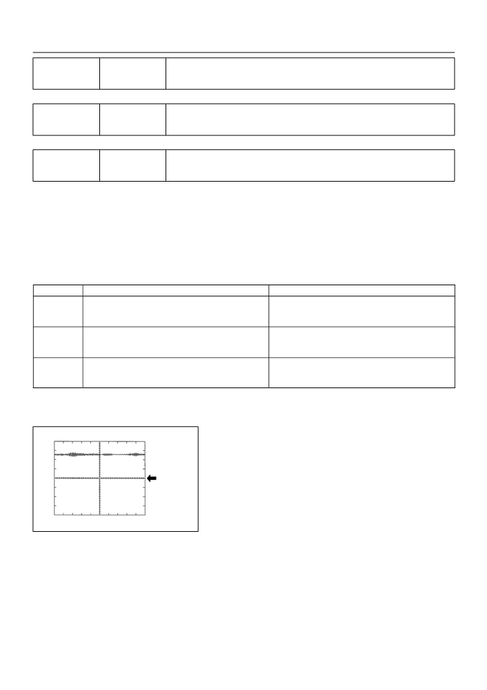
Reference: Inspection using the oscilloscope.
KNK1 Signal Waveform
1V/ DIV
(1)
After warming up run the engine at 4,000 rpm,
check the waveform between terminal KNK1 and
EKNK of the ECM connector.
GND
1 msec./ Division
A85286
MONITOR DESCRIPTION
The knock sensor, located on the cylinder block, detects spark knock. When spark knock occurs, the sensor
picks-up vibrates in a specific frequency range. When the ECM detects the voltage in this frequency range,
it retards the ignition timing to suppress the spark knock.
The ECM also senses background engine noise with the knock sensor and uses this noise to check for faults
in the sensor. If the knock sensor signal level is too low for more than 10 seconds, and if the knock sensor
output voltage is out of normal range, the ECM interprets this as a fault in the knock sensor and sets a DTC.

05-164
DIAGNOSTICS
- SFI SYSTEM (April, 2003)
MONITOR STRATEGY
P0325
Knock sensor (bank 1) range check or rationality
Related DTCs
P0327
Knock sensor (bank 1) range check (low voltage)
P0328
Knock sensor (bank 1) range check (high voltage)
Main sensors
Knock sensor
Required sensors/components
Crankshaft position sensor, camshaft position sensor, engine coolant
Related sensors
temperature sensor, mass air flow sensor
Frequency of operation
Continuous
Duration
10 seconds
MIL operation
Immediately
Sequence of operation
None
TYPICAL ENABLING CONDITIONS
Specification
Item
Minimum
Maximum
The monitor will run whenever the follow-
See ”List of Disable a Monitor” (On page 05-25)
ing DTCs are not present
Battery voltage
10 V
-
Idle
OFF
Time after engine start
5 seconds
-
Engine coolant temperature
60_C (140_F)
-
Intake air amount per revolution
0.3 g/rev
-
TYPICAL MALFUNCTION THRESHOLDS
Detection Criteria
Threshold
P0325 (Range check/Rationality):
Time while the voltage output of the knock sensor is below
10 seconds
the specific threshold
P0325 (Fluttering):
Knock sensor voltage
Less than 0.5 V and More than 4.5 V
P0327:
Knock sensor voltage
Less than 0.5 V
P0328:
Knock sensor voltage
More than 4.5 V

05-165
DIAGNOSTICS
- SFI SYSTEM (April, 2003)
WIRING DIAGRAM
ECM
(Shielded)
1
B
E4
KNK1
K1
Knock Sensor
2
2
1
W
EKNK
E4
A
A
J4
J5
Junction
Connector
BR
EB
A84875
INSPECTION PROCEDURE
HINT:
Read freeze frame data using the hand−held tester or the OBD II scan tool. Freeze frame data records the
engine conditions when a malfunction is detected. When troubleshooting, it is useful for determining whether
the vehicle was running or stopped, the engine was warmed up or not, the air-fuel ratio was lean or rich,
etc. at the time of the malfunction.
1
READ OUTPUT DTC
(a) Clear the DTC.
(b) Warm up the engine.
(c)
Run the engine at 3,000 rpm for 10 seconds or more.
(d) Connect the hand-held tester or the OBD II scan tool to the DLC3.
(e) Turn the ignition switch ON and push the hand-held tester or the OBD II scan tool main switch ON.
(f)
Select the item ”DIAGNOSIS / ENHANCED OBD II / DTC INFO / CURRENT CODES”.
(g) Read the DTCs.
Result :
Display (DTC output)
Proceed to
P0325
A
”P0325, P0327 and/or P0328”
B
No output
C
B
Go to step 3
C CHECK FOR INTERMITTENT PROBLEMS
(See page 05-41)
A