Toyota Corolla (2004+). Manual - part 63

05-166
DIAGNOSTICS
- SFI SYSTEM (April, 2003)
2
INSPECT KNOCK SENSOR
(a) Check the knock sensor installation.
Torque: 20 N m (204 kgf cm, 15 ft lbf)
A64029
NG TIGHTEN SENSOR
OK
3
CHECK HARNESS AND CONNECTOR(ECM - KNOCK SENSOR)
(a) Disconnect the E4 ECM connector.
(b) Measure the resistance between terminals of the E4 ECM
E4
connector.
Standard:
Tester Connection
Specified Condition
KNK1 (E4-1) - EKNK (E4-2)
120 to 280 KW at 20 _C (68 _F)
EKNK
(c)
Reconnect the ECM connector.
KNK1
NG Go to step 5
ECM Connector
A65745
OK
4
INSPECT ECM(KNK1 VOLTAGE)
(a) Disconnect the E4 ECM connector.
(b) Turn the ignition switch ON.
(c)
Measure the voltage between terminals of the E4 ECM
terminals.
Standard:
Tester Connection
Specified Condition
KNK1 (E4-1) - EKNK (E4-2)
4.5 to 5.5 V
EKNK (-)
KNK1(+)
(d) Reconnect the ECM connector.
ECM Connector
A84937
NG REPLACE ECM (See page 10-11)
OK

05-167
DIAGNOSTICS
- SFI SYSTEM (April, 2003)
CHECK FOR INTERMITTENT PROBLEMS (See page 05-41)
NOTICE:
Fault may be intermittent. Check harness and connectors carefully.
5
INSPECT KNOCK SENSOR
(a) Remove the K1 knock sensor.
Ohmmeter
(b) Measure the resistance between the terminals.
Standard:
Tester Connection
Specified Condition
KNK1 (K1-1) - EKNK (K1-2)
120 to 280 KW aKt 20 _C (68 _F)
(c)
Reinstall the knock sensor.
A65174
NG REPLACE KNOCK SENSOR
OK
REPAIR OR REPLACE HARNESS OR CONNECTOR

05-168
DIAGNOSTICS
- SFI SYSTEM (April, 2003)
052NO-11
DTC
P0335
CRANKSHAFT POSITION SENSOR ”A”
CIRCUIT
DTC
P0339
CRANKSHAFT POSITION SENSOR ”A”
CIRCUIT INTERMITTENT
CIRCUIT DESCRIPTION
The crankshaft position sensor (NE signal) consists of a magnet, iron core and pickup coil.
The NE signal plate (crankshaft position sensor plate) has 34 teeth and is installed on the crankshaft. The
NE signal sensor generates 34 signals for each engine revolution. This sensor monitors a plate (timing rotor)
located on the crankshaft timing pulley and is used by the ECM to detect crankshaft angle and engine speed
(RPM/NE). As the crankshaft timing pulley rotates through an engine revolution, this sensor communicates
the rotation of the NE signal plate as a pulse signal to the ECM. Based on the signal, the ECM controls fuel
injection time and ignition timing.
DTC No.
DTC Detection Condition
Trouble Area
No crankshaft position sensor signal to ECM during cranking
(2 trip detection logic)
P0335
No crankshaft position sensor signal to ECM with engine
speed 600 rpm or more (2 trip detection logic)
F Open or short in crankshaft position sensor circuit
In condition (a), (b) and (c), when no crankshaft position sen-
F Crankshaft position sensor
sor (NE+) signal is input for 0.05 seconds or more.
F Signal plate (crankshaft)
(a) Engine revolution 1,000 rpm or more
F ECM
P0339
(b) STA signal is OFF
(c) 3 seconds or more has lapsed after STA signal is switched
from ON to OFF.
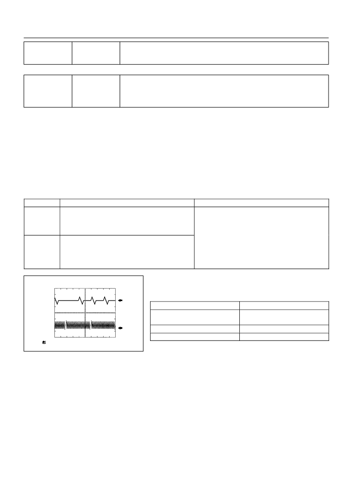
Reference: Inspection using the oscilloscope.
HINT:
CH1
The correct waveform is as shown on the left.
GND
(G22+)
Item
Contents
CH1: G22+ - NE-
Terminal
CH2: NE+ - NE-
CH2
GND
Equipment Set
5V/Division, 20ms/Division
(NE+)
Condition
During cranking or idling
A84612

05-169
DIAGNOSTICS
-
SFI SYSTEM (April, 2003)
MONITOR DESCRIPTION
If there is no signal from the crankshaft sensor despite the engine revolving, the ECM interprets this as a
malfunction of the sensor.
MONITOR STRATEGY
Crankshaft position sensor range check or ratio-
Related DTCs
P0335
nality
Main sensors
Crankshaft position sensor
Required sensors/components
Related sensors
Engine speed sensor
Frequency of operation
Continuous
Duration
Case 1: 4.7 seconds, Case 2: 0.5 second
MIL operation
2 driving cycles
Sequence of operation
None
TYPICAL ENABLING CONDITIONS
Specification
Item
Minimum
Maximum
The monitor will run whenever the follow-
See ”List of Disable a Monitor” (On page 05-25)
ing DTCs are not present
Case 1:
Starter
ON
Minimum battery voltage while starter ON
-
11 V
Case 2:
Engine speed
600 rpm
-
Starter
OFF
Time after starter ON to OFF
3 seconds
-
TYPICAL MALFUNCTION THRESHOLDS
Detection Criteria
Threshold
Case 1:
Engine speed signal
No signal for 4.7 seconds
Case 2:
Engine speed signal
No signal for 0.5 second
05-170
DIAGNOSTICS
- SFI SYSTEM (April, 2003)
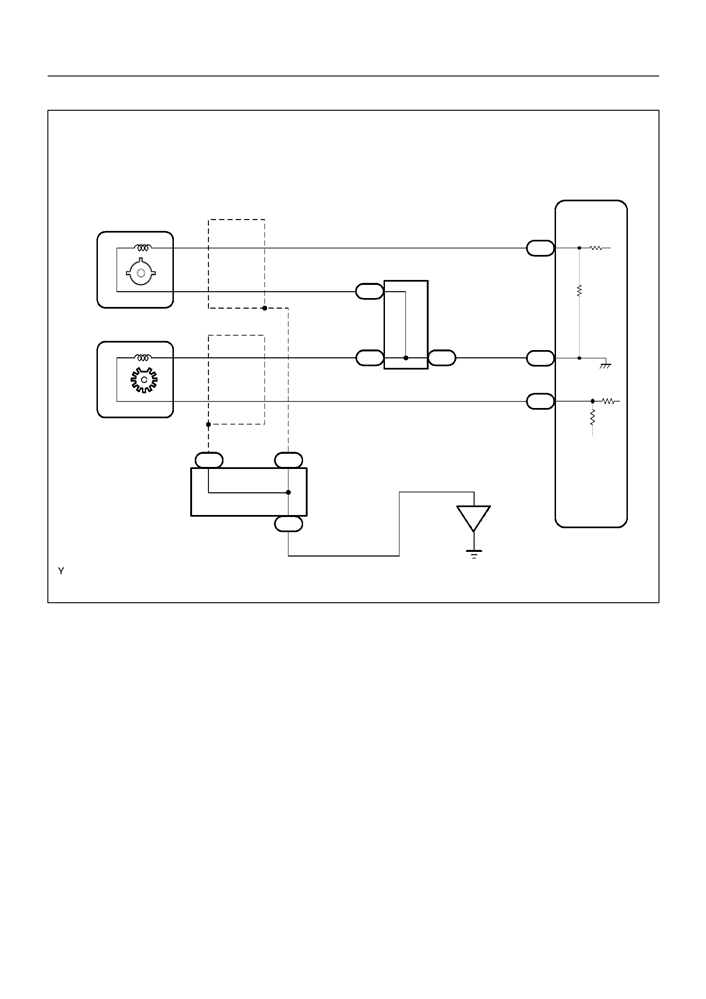
WIRING DIAGRAM
ECM
C1
(Shielded)
Camshaft Position Sensor
26
1
B
G22+
E3
A
2
W
J3
Junction
C3
Connector
(Shielded)
Crankshaft Position Sensor
E
E
34
2
W
W
J2
J2
E3
NE-
27
1
B
NE+
E3
J5
A
J5
A
Junction
Connector
EB
J4
A
BR
A84876
INSPECTION PROCEDURE
HINT:
F
Perform the troubleshooting of DTC P0335 first. If no trouble is found, troubleshoot the engine me-
chanical systems.
F
Read freeze frame data using the hand−held tester or the OBD II scan tool. Freeze frame data records
the engine conditions when a malfunction is detected. When troubleshooting, it is useful for determin-
ing whether the vehicle was running or stopped, the engine was warmed up or not, the air-fuel ratio
was lean or rich, etc. at the time of the malfunction.
F
READ VALUE OF HAND-HELD TESTER OR OBD II SCAN TOOL
(a) Connect the hand-held tester or the OBD II scan tool to the DLC3.
(b) Start the engine and push the hand-held tester or the OBD II scan tool main switch ON.
(c) Select the item ”DIAGNOSIS / ENHANCED OBD II / DATA LIST / ALL / ENGINE SPD”.
F
The engine speed can be confirmed in DATA LIST using the hand-held tester or OBD II scan tool. If
there is no NE signals from the crankshaft position sensor despite the engine revolving, the engine
speed will be indicated as zero. If voltage output of the crankshaft position sensor is insufficient, the
engine speed will be indicated as lower PRM (than the actual RPM).
05-171
DIAGNOSTICS
- SFI SYSTEM (April, 2003)
1
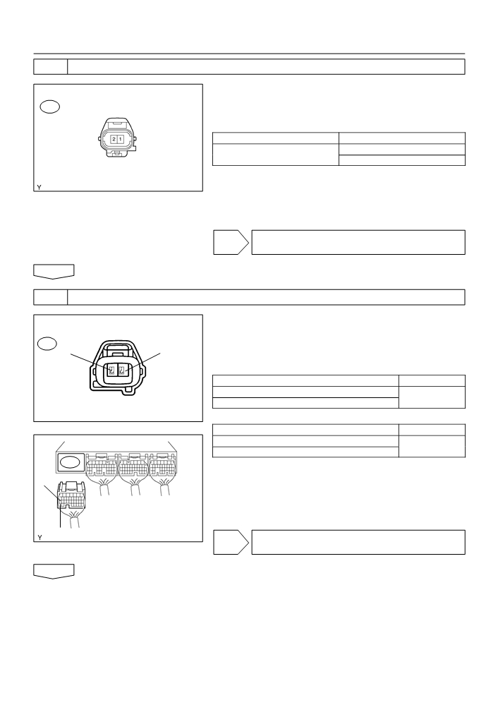
INSPECT CRANKSHAFT POSITION SENSOR(RESISTANCE)
(a) Disconnect the C43crankshaft position sensor connector.
Component Side:
(b) Measure the resistance between the terminals of the
C3
Crankshaft Position Sensor
crankshaft position sensor connector.
Standaed:
Tester Connection
Specified Condition
985 to 1,600 W at cold
1
- 2
1,265 to 1,890 W at hot
Front View
NOTICE:
A73303
”Cold” and ”Hot” shown above mean the temperature of
the coils themselves. ”Cold” is from -10
_C (14_F) to 50 _C
(122 _F) and ”Hot” is from 50
_C (122 _F) to 100 _C (212 _F).
(c)
Reconnect the crankshaft position sensor connector.
NG REPLACE CRANKSHAFT POSITION SENSOR
(See page 18-2)
OK
2
CHECK HARNESS AND CONNECTOR(CRANKSHAFT POSITION SENSOR - ECM)
(a) Disconnect the C3 crankshaft position sensor connector.
Wire Harness Side:
Crankshaft Position Sensor Connector
(b) Disconnect the E3 ECM connector.
C3
(c)
Check the resistance between the wire harness side con-
NE+
NE-
nectors.
Standard (Check for open):
Tester connection
Specified Condition
NE+ (C3-1) - NE+ (E3-27)
Below 1 W
NE- (C3-2) - NE- (E3-34)
Front View
A84567
Standard (Check for short):
Tester connection
Specified Condition
NE+ (C3-1) or NE+ (E3-27) - Body ground
10 kW or higher
NE- (C3-2) or NE- (E3-34) - Body ground
E3
(d) Reconnect the ECM connector.
(e) Reconnect the crankshaft position sensor connector.
NE+
NE-
ECM Connector
A65743
NG REPAIR OR REPLACE HARNESS OR
CONNECTOR
OK

05-172
DIAGNOSTICS
- SFI SYSTEM (April, 2003)
3
CHECK SENSOR INSTALLATION(CRANKSHAFT POSITION SENSOR)
(a) Check the crankshaft position sensor installation .
NG TIGHTEN SENSOR
OK
4
CHECK CRANKSHAFT POSITION SENSOR PLATE(TEETH OF SENSOR
PLATE(CRANKSHAFT))
(a) Check the teeth of the sensor plate.
NG REPLACE CRANKSHAFT POSITION SENSOR
PLATE (CRANKSHAFT)
OK
REPLACE ECM (See page 10-11)
05-173
DIAGNOSTICS
- SFI SYSTEM (April, 2003)
052NP-12
DTC
P0340
CAMSHAFT POSITION SENSOR ”A”
CIRCUIT (BANK 1 OR SINGLE SENSOR)
DTC
P0341
CAMSHAFT POSITION SENSOR ”A”
CIRCUIT RANGE/PERFORMANCE (BANK 1
OR SINGLE SENSOR)
CIRCUIT DESCRIPTION
The camshaft position sensor (G22+ signal) consists of a magnet, iron core and pickup coil.
The G22+ signal plate has 3 teeth on its outer circumference and is installed on the camshaft timing pulley.
When the camshafts rotate, the protrusion on the signal plate and the air gap on the pickup coil changes,
causing fluctuations in the magnetic field and generating an electromotive force in the pickup coil.
The NE+ signal plate (crankshaft timing pulley) has 34 teeth and is installed to the crankshaft. The NE+ signal
sensor generates 34 signals at every engine revolution. The ECM detects the crankshaft angle and the en-
gine revolution based on the NE+ signals, and the cylinder and the angle of the VVT based on the combina-
tion of the G22+ and NE+ signals.
DTC No.
DTC Detection Condition
Trouble Area
F No camshaft position sensor signal to ECM during cranking
(2 trip detection logic)
P0340
F No camshaft position sensor signal to ECM with engine
F Open or short in camshaft position sensor circuit
speed 600 rpm or more (1 trip detection logic)
F Camshaft position sensor
While crankshaft rotates twice, camshaft position sensor signal
F Camshaft timing pulley
is input to ECM 12 times or more (1 trip detection logic)
F Timing chain has jumped a tooth
P0341
F Hint:
F ECM
Under normal condition, the camshaft position sensor is input
into the ECM 3 times per 2 engine revolutions
Reference: Inspection using the oscilloscope.
HINT:
CH1
The correct waveform is as shown on the left.
(G22+)
GND
Item
Contents
CH1: G22+ - NE-
Terminal
CH2
CH2: NE+ - NE-
(NE+)
GND
Equipment Set
5V/DIV, 20ms/DIV
Condition
During cranking or idling
A84613

05-174
DIAGNOSTICS
- SFI SYSTEM (April, 2003)
MONITOR DESCRIPTION
If there is no signal from the camshaft position sensor despite the engine revolving, or if the rotation of the
camshaft and the crankshaft is not synchronized, the ECM interprets this as a malfunction of the sensor.
MONITOR STRATEGY
Camshaft position sensor (bank 1) range check
P0340
or rationality
Related DTCs
Camshaft position sensor (bank 1) range check
P0341
or rationality
Main sensors
Camshaft position sensor
Required sensors/components
Related sensors
Crankshaft position sensor, engine speed sensor
Frequency of operation
Continuous
Duration
5 seconds
P0340 case 2 (mis-aligned) and P0341: Immediately
MIL operation
P0340 case 1 (no signal): 2 driving cycles
Sequence of operation
None
TYPICAL ENABLING CONDITIONS
Specification
Item
Minimum
Maximum
The monitor will run whenever the follow-
See ”List of Disable a Monitor” (On page 05-25)
ing DTCs are not present
P0340 Case 1 (No signal):
Starter
ON
Minimum battery voltage while starter ON
-
11 V
P0340 Case 2 (Mis-aligned):
Engine speed
600 rpm
-
Starter
OFF
P0341:
Engine speed
600 rpm
-
Time after restart
180_CA
-
TYPICAL MALFUNCTION THRESHOLDS
Detection Criteria
Threshold
P0340 Case 1 (No signal):
Camshaft position sensor signal
No signal
P0340 Case 2 (Mis-aligned):
Crankshaft/camshaft alignment is mis-aligned (judged by comparing the crankshaft position to the camshaft position)
Camshaft position sensor signal: No input in appropriate timing.
P0341:
Crankshaft/Camshaft alignment
Mis-aligned
Camshaft position sensor count
12 or more / 720_CA (= Engine 2 revolutions)
COMPONENT OPERATING RANGE
Parameter
Standard Value
Camshaft position sensor signal input during every 720_CA
3

05-175
DIAGNOSTICS
- SFI SYSTEM (April, 2003)
WIRING DIAGRAM
Refer to DTC P0335 on page 05-168.
INSPECTION PROCEDURE
HINT:
Read freeze frame data using the hand−held tester or the OBD II scan tool. Freeze frame data records the
engine conditions when a malfunction is detected. When troubleshooting, it is useful for determining whether
the vehicle was running or stopped, the engine was warmed up or not, the air-fuel ratio was lean or rich,
etc. at the time of the malfunction.
1
INSPECT CAMSHAFT POSITION SENSOR(RESISTANCE)
(a) Measure the resistance between the terminals of cam-
Component Side:
shaft position sensor connector.
C1
Standard:
Tester Connection
Specified Condition
1,630 to 2,740 W at cold
1
- 2
2,065 to 3,225 W at hot
NOTICE:
”Cold” and ”Hot” shown above mean the temperature of
Camshaft Position Sensor
A73303
the coils themselves. ”Cold” is from -10
_C (14_F) to 50 _C
(122 _F) and ”Hot” is from 50
_C (122 _F) to 100 _C (212 _F).
NG REPLACE CAMSHAFT POSITION SENSOR
OK
2
CHECK HARNESS AND CONNECTOR(CAMSHAFT POSITION SENSOR - ECM)
(a) Disconnect the C1 camshaft position sensor connector.
Wire Harness Side:
Camshaft Position Sensor Connector
(b) Disconnect the E3 ECM connector.
C1
(c)
Check the resistance between the wire harness side con-
nectors.
Standard (Check for open):
Tester Connection
Specified Condition
G+ (C1-1) - G22+ (E3-26)
Below 1 W
G+
G-
G- (C1-2) - NE- (E3-34)
Front View
A66132
Standard (Check for short):
Tester Connection
Specified Condition
G+ (C1-1) or G22+ (E3-26) - Body ground
10 kW or higher
G- (C1-2) or NE- (E3-34) - Body ground
E3
(d) Reconnect the ECM connector.
G22+
(e) Reconnect the camshaft position sensor connector.
NG REPAIR OR REPLACE HARNESS OR
NE-
ECM Connector
A65743
CONNECTOR
OK

05-176
DIAGNOSTICS
- SFI SYSTEM (April, 2003)
3
CHECK SENSOR INSTALLATION(CAMSHAFT POSITION SENSOR)
(a) Check the camshaft position sensor installation.
NG TIGHTEN SENSOR
OK
4
CHECK CAMSHAFT TIMING GEAR ASSY(TEETH OF PLATE)
(a) Check the teeth of the signal plate.
NG REPLACE CAMSHAFT TIMING GEAR ASSY
OK
REPLACE ECM (See page 10-11)

05-177
DIAGNOSTICS
-
SFI SYSTEM (April, 2003)
05DIO-01
DTC
P0351
IGNITION COIL ”A” PRIMARY/SECONDARY
CIRCUIT
DTC
P0352
IGNITION COIL ”B” PRIMARY/SECONDARY
CIRCUIT
DTC
P0353
IGNITION COIL ”C” PRIMARY/SECONDARY
CIRCUIT
DTC
P0354
IGNITION COIL ”D” PRIMARY/SECONDARY
CIRCUIT
CIRCUIT DESCRIPTION
HINT:
F
These DTCs indicate a malfunction related to the primary circuit.
F
If DTC P0351 is displayed, check the No.1 ignition coil with igniter circuit.
F
If DTC P0352 is displayed, check the No.2 ignition coil with igniter circuit.
F
If DTC P0353 is displayed, check the No.3 ignition coil with igniter circuit.
F
If DTC P0354 is displayed, check the No.4 ignition coil with igniter circuit.
A Direct Ignition System (DIS) is used on this vehicle. The DIS improves the ignition timing accuracy, reduces
high-voltage loss, and enhances the overall reliability of the ignition system by eliminating the distributor.
The DIS is a 1-cylinder ignition system which ignites one cylinder with one ignition coil. In the 1-cylinder
ignition system, the one spark plug is connected to the end of the secondary winding. High voltage generated
in the secondary winding is applied directly to the spark plug. The spark of the spark plug passes from the
center electrode to the ground electrode.
The ECM determines the ignition timing and outputs the ignition signals (IGT) for each cylinder. Using the
ignition (IGT) signal, the ECM turns on and off the power transistor inside the igniter and this switches on
and off the current to the primary coil. When the current flow to the primary coil is cut off, high-voltage is
generated in the secondary coil and this voltage is applied to the spark plugs to spark inside the cylinders.
As the ECM cuts the current to the primary coil, the igniter sends back the ignition confirmation (IGF) signal
for each cylinder ignition to the ECM.

05-178
DIAGNOSTICS
- SFI SYSTEM (April, 2003)
From Battery
ECM
Igniter
No.1 Ignition
Coil with igniter
IGT1
Crankshaft
No. 1 Spark Plug
Position
IGF
Sensor
Ignition Coil
IGT2
No.2 Ignition
No. 2 Spark Plug
Coil with igniter
Camshaft
Position
Sensor
IGT3
No.3 Ignition
No. 3 Spark Plug
Coil with igniter
Other Sensors
IGT4
No.4 Ignition
No. 4 Spark Plug
(Engine Coolant Tem-
Coil with igniter
perature Sensor, Mass
Air Flow Sensor, Throttle
Position Sensor, etc.)
TACH
To Tachometer
A85099
DTC No.
DTC Detection Condition
Trouble Area
F Ignition system
P0351
F Open or short in IGF or IGT circuit from ignition coil with ignit-
P0352
No IGF signal to ECM while engine is running
er to ECM (ignition coil circuit 1 through 4)
P0353
F Ignition coil with igniter (ignition coil circuit 1 through 4)
P0354
F ECM

05-179
DIAGNOSTICS
- SFI SYSTEM (April, 2003)
MONITOR DESCRIPTION
Ignition Coil with Igniter
IGT
ignition coil
ECM
Igniter
IGF
Ignition signal
(IGT)
Normal
Ignition
confirmation
Malfunction
signal (IGF)
Circuit Open
time
A82388
If the ECM does not receive the ignition confirmation signal (IGF) after sending the ignition signal (IGT), it
interprets this as a fault in the igniter and sets a DTC.
MONITOR STRATEGY
P0351
No. 1 ignition coil with igniter circuit malfunction
P0352
No. 2 ignition coil with igniter circuit malfunction
Related DTCs
P0353
No. 3 ignition coil with igniter circuit malfunction
P0354
No. 4 ignition coil with igniter circuit malfunction
Required sensors/components
Igniter
Frequency of operation
Continuous
Duration
0.256 seconds
MIL operation
Immediately
Sequence of operation
None

05-180
DIAGNOSTICS
- SFI SYSTEM (April, 2003)
TYPICAL ENABLING CONDITIONS
Specification
Item
Minimum
Maximum
The monitor will run whenever the follow-
See ”List of Disable a Monitor” (On page 05-25)
ing DTCs are not present
Engine speed
-
1,500 rpm
Following condition is met:
(a) or (b)
(a) Following conditions are met:
1 and 2
1. Engine speed
-
500 rpm
2. Battery voltage
6 V
-
(b) Following conditions are met:
1 and 2
1. Engine speed
500 rpm
-
2. Battery voltage
10 V
-
TYPICAL MALFUNCTION THRESHOLDS
Detection Criteria
Threshold
Ignition signal fail count
More than 2 times
”Ignition signal fail count” works as follows:
When IGF should have returned despite sending IGT
COMPONENT OPERATING RANGE
Standard Value
Confirmed signal number equals ignition signal number