Toyota Corolla (2004+). Manual - part 59

05-106
DIAGNOSTICS
- SFI SYSTEM (April, 2003)
NOTICE:
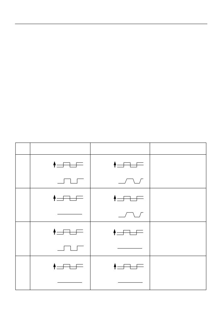
There is a delay of few seconds in the sensor 1 (front sensor) output, and there is about 20 seconds
delay at maximum in the sensor 2 (rear sensor).
Output voltage of heated oxygen
Output voltage of heated oxygen
Mainly suspect
sensor (sensor 1: front sensor)
sensor (sensor 2: rear sensor)
trouble area
Injection volume
Injection volume
+25 %
+25 %
-12.5 %
-12.5 %
Case 1
Output voltage
Output voltage
More than 0.5 V
More than 0.5 V
OK
OK
Less than 0.4 V
Less than 0.4 V
Injection volume
Injection volume
+25 %
+25 %
-12.5 %
-12.5 %
Sensor 1: front sensor
Output voltage
Output voltage
(sensor 1, heater, sensor 1
Case 2
circuit)
More than 0.5 V
No reaction
NG
OK
Less than 0.4 V
Injection volume
Injection volume
+25 %
+25 %
-12.5 %
Sensor 2: rear sensor
-12.5 %
Output voltage
Output voltage
(sensor 2, heater, sensor 2
Case 3
circuit)
More than 0.5 V
No reaction
NG
OK
Less than 0.4 V
Injection volume
Injection volume
+25 %
+25 %
Extremely rich or lean actual
-12.5 %
-12.5 %
air-fuel ratio
Case 4
Output voltage
Output voltage
(Injector, fuel pressure, gas
leakage in exhaust system,
No reaction
NG
No reaction
NG
etc.)
The following of A/F CONTROL procedure enables the technician to check and graph the voltage outputs
of both the heated oxygen sensors.
For displaying the graph indication, enter ”ACTIVE TEST / A/F CONTROL / USER DATA”, then select ”O2S
B1S1 and O2S B1S2” by pressing ”YES” button and push ”ENTER” button before pressing ”F4” button.
NOTICE:
If the vehicle is short of fuel, the air-fuel ratio becomes LEAN and heated oxygen sensor DTCs will
be recorded, and the MIL then comes on.
HINT:
F
If different DTCs related to different systems that have terminal E2 as the ground terminal are output
simultaneously, terminal E2 may be open.
F
Read freeze frame data using the hand−held tester or the OBD II scan tool. Freeze frame data records
the engine conditions when a malfunction is detected. When troubleshooting, it is useful for determin-
ing whether the vehicle was running or stopped, the engine was warmed up or not, the air-fuel ratio
was lean or rich, etc. at the time of the malfunction.
F
A high heated oxygen sensor (sensor 1) voltage (0.5 V or more) could be caused by a rich air fuel mix-
ture. Check for conditions that would cause the engine to run rich.
F
A low heated oxygen sensor (sensor 1) voltage (0.4 V or less) could be caused by a lean air fuel mix-
ture. Check for conditions that would cause the engine to run lean.

05-107
DIAGNOSTICS
- SFI SYSTEM (April, 2003)
1
CHECK OTHER DTC OUTPUT(IN ADDITION TO HEATED OXYGEN SENSOR
DTCS)
(a) Connect the hand-held tester or the OBD II scan tool to the DLC3.
(b) Turn the ignition switch ON and push the hand-held tester or the OBD II scan tool main switch ON.
(c)
Select the item ”DIAGNOSIS / ENHANCED OBD II / DTC INFO / CURRENT CODES”.
(d) Read the DTCs.
Result:
Display (DTC output)
Proceed to
”P0130, P2195 and/or P2196”
A
”P0130, P2195 and/or P2196” and other DTCs
B
HINT:
If any other codes besides P0130, P2195 and/or P2196 are output, perform the troubleshooting for those
DTCs first.
B
GO TO RELEVANT DTC CHART
(See page 05-35)
A
2
READ VALUE OF HAND-HELD TESTER OR OBD II SCAN TOOL(OUTPUT
VOLTAGE OF HEATED OXYGEN SENSOR)
(a) Connect the hand-held tester or the OBD II scan tool to the DLC3.
(b) Start the engine and push the hand-held tester or the OBD II scan tool main switch ON.
(c)
Select the item ”DIAGNOSIS / ENHANCED OBD II / DATA LIST / ALL / O2S B1S1”.
(d) Warm up the heated oxygen sensor with the engine speed at 2,500 rpm for approximately 90 seconds.
(e) Read the output voltage of the heated oxygen sensor during idling.
Heated oxygen sensor output voltage:
Alternates repeatedly between less than 0.4 V and more than 0.5 V (See the following table).
A85076
OK Go to step 9
NG

05-108
DIAGNOSTICS
- SFI SYSTEM (April, 2003)
3
INSPECT HEATED OXYGEN SENSOR(HEATER RESISTANCE)
(a) Disconnect the H5 heated oxygen sensor connector.
Component Side:
Heated Oxygen Sensor
(b) Measure the resistance between the terminals of the
H5
HT
heated oxygen sensor connector.
Bank 1,
+B
Sensor 1
Standard:
Tester Connection
Specified Condition
HT (H5-1) - +B (H5-2)
5 to 10 W at 20 _C (68 _F)
HT (H5-1) - E1 (H5-4)
10 kW or higher
E1
OX
(c)
Reconnect the heated oxygen sensor connector.
Front View
A79112
NG REPLACE HEATED OXYGEN SENSOR
OK
4
INSPECT EFI RELAY
(a) Remove the EFI relay from the engine room R/B.
(b) Check for continuity in the EFI relay.
Standard:
Tester Connection
Specified Condition
1 - 2
Continuity
No continuity
3 - 5
Continuity
(Apply battery voltage to terminals 1 and 2)
(c)
Reinstall the EFI relay.
E34090
NG REPLACE EFI RELAY
OK

05-109
DIAGNOSTICS
- SFI SYSTEM (April, 2003)
5
CHECK HARNESS AND CONNECTOR(HEATED OXYGEN SENSOR - ECM)
Wire Harness Side:
(a) Disconnect the H5 heated oxygen sensor connector.
H5
Heated Oxygen Sensor Connector
(b) Disconnect the E4 ECM connector.
Bank 1 Sensor 1
(c)
Check the resistance between the wire harness side con-
nectors.
HT
Standard (Check for open):
Tester Connection
Specified Condition
OX
HT (H5-1) - HT1A (E4-4)
Below 1 W
OX (H5-3) - OX1A (E4-23)
Front View
A79114
Standard (Check for short):
Tester Connection
Specified Condition
HT (H5-1) or HT1A (E4-4) - Body ground
10 kW or higher
OX (H5-3) or OX1A (E4-23) - Body ground
E4
(d) Reconnect the ECM connector.
(e) Reconnect the heated oxygen sensor connector.
HT1A
OX1A
ECM Connector
A55007
Reference (Bank 1 Sensor 1 System Drawing)
ECM
EFI Relay
Heated Oxygen Sensor
From
EFI Fuse
Heater
HT1A
Battery
Sensor
OX1A
From
Duty
Terminal 6 of
Control
Ignition Switch
Ground Ground
A82244
NG REPAIR OR REPLACE HARNESS OR
CONNECTOR
OK

05-110
DIAGNOSTICS
- SFI SYSTEM (April, 2003)
6
CHECK AIR INDUCTION SYSTEM
(a) Check the air induction system for vacuum leaks.
NG REPAIR OR REPLACE AIR INDUCTION SYSTEM
OK
7
CHECK FUEL PRESSURE (See page 11-5)
(a) Check the fuel pressure (high or low pressure).
NG REPAIR OR REPLACE FUEL SYSTEM
OK
8
INSPECT FUEL INJECTOR ASSY(INJECTION AND VOLUME) (See page 11-7)
NG REPLACE FUEL INJECTOR ASSY
OK
REPLACE HEATED OXYGEN SENSOR
9
PERFORM CONFIRMATION DRIVING PATTERN
HINT:
Clear all DTCs prior to performing the confirmation driving pattern.
GO
10
READ OUTPUT DTC(HEATED OXYGEN SENSOR DTCS ARE OUTPUT AGAIN)
(a) Connect the hand-held tester or the OBD II scan tool to the DLC3.
(b) Turn the ignition switch ON and push the hand-held tester or the OBD II scan tool main switch ON.
(c)
Read the DTC using the hand-held tester or the OBD II scan tool.
Result:
Display (DTC output)
Proceed to
”P0130, P2195 and/or P2196”
A
”P0130, P2195 and/or P2196” are not output
B
B
CHECK FOR INTERMITTENT PROBLEMS
(See page 05-41)
A
REPLACE HEATED OXYGEN SENSOR

05-111
DIAGNOSTICS
- SFI SYSTEM (April, 2003)
05DIK-01
DTC
P0133
OXYGEN SENSOR CIRCUIT SLOW
RESPONSE (BANK 1 SENSOR 1)
CIRCUIT DESCRIPTION
Refer to DTC P0130 on page 05-101.
DTC No.
DTC Detection Condition
Trouble Area
F Open or short in heated oxygen sensor (bank 1 sensor 1)
After engine has been warmed up, if response time that heated
circuit
oxygen sensor’s output voltage reaches from RICH to LEAN.
F Heated oxygen sensor (bank 1 sensor 1)
or from LEAN to RICH, is 0.6 second or more during idling.
F Heated oxygen sensor heater (bank 1 sensor 1)
(2 trip detection logic)
F EFI relay
P0133
F Air induction system
F Fuel pressure
If response time of heated oxygen sensor’s output voltage in
F Injector
one RICH-LEAN cycle is 6 seconds or more during idling. (2
F ECM
trip detection logic)
F
HINT:
Sensor 1 refers to the sensor closest to the engine assembly.
MONITOR DESCRIPTION
Slow slope condition:
Rich to Lean time
Lean to Rich time
Rich
0.55
0.45
0.40
Lean
Lean to Rich / Rich to Lean time definition
Time
A79137
The engine control module (ECM) uses the heated oxygen sensor information to regulate the air-fuel ratio
close to a stoichiometric ratio. This maximizes the catalytic converter’s ability to purify the exhaust gases.
The sensor detects oxygen levels in the exhaust gas and sends this signal to the ECM.
The inner surface of the sensor element is exposed to the outside air. The outer surface of the sensor ele-
ment is exposed to the exhaust gas. The sensor element is made of the platinum coated zirconia and in-
cludes an integrated heating element. The heated oxygen sensor has the characteristic whereby its output
voltage change suddenly in the vicinity of the stoichiometric air-fuel ratio. The heated oxygen sensor gener-
ates waveform of a voltage between 0 V and 1 V in response to the oxygen concentration in exhaust gas.
When the output voltage of the heated oxygen sensor is 0.55 V or more, the ECM judges that the air-fuel
ratio is RICH. When it is 0.40 V or less, the ECM judges that the air-fuel ratio is LEAN.
The ECM monitors the response feature of the heated oxygen sensor. If the response time of the sensor
output status change from RICH to LEAN or vice versa becomes longer, the ECM interprets this as a mal-
function in the heated oxygen sensor and sets a DTC.

05-112
DIAGNOSTICS
- SFI SYSTEM (April, 2003)
Frequency condition:
One Cycle
Rich side frequency
O2 Sensor Voltage
0.45V
Lean side frequency
A84946
MONITOR STRATEGY
Related DTCs
P0133
Front heated oxygen sensor response monitor
Main sensors
Front heated oxygen sensor
Required sensors/components
Related sensors
Crank shaft position sensor, vehicle speed sensor, mass air flow sensor
Frequency of operation
Once per drive cycles
Duration
Within 60 seconds
MIL operation
2 driving cycles
Sequence of operation
None
TYPICAL ENABLING CONDITION
Specification
Item
Minimum
Maximum
The monitor will run whenever the follow-
See ”List of Disable a Monitor” (On page 05-25)
ing DTCs are not present
Frequency idle condition:
There is a history that the following condition (a) and (b) were met for 20seconds
(a) Vehicle speed
25 mph (40 km/h)
-
(b) Engine speed
900 rpm
-
Time after engine start
120 seconds
-
Idle
ON
Vehicle speed
-
3 mph (5 km/h)
Fuel system status
Closed loop
Engine coolant temperature
40_C (104_F)
-
Frequency cruise condition:
There is a history that the following condition (a) and (b) were met for 20seconds
(a) Vehicle speed
25 mph (40 km/h)
-
(b) Engine speed
900 rpm
-
Intake air amount
5 g/s
14.5 g/s
Time after engine start
120 sec
-
Idle
OFF
Fuel system status
Closed loop

05-113
DIAGNOSTICS
-
SFI SYSTEM (April, 2003)
Engine speed
1,000 rpm
3,500 rpm
Engine coolant temperature
70_C (104_F)
-
Slow slope condition:
There is a history that the following condition (a) and (b) were met for 20seconds
(a) Vehicle speed
25 mph (40 km/h)
-
(b) Engine speed
900 rpm
-
Time after engine start
120 seconds
-
Idle
ON
Vehicle speed
-
3 mph (5 km/h)
Fuel system status
Closed loop
Engine coolant temperature
40_C (104_F)
-
TYPICAL MALFUNCTION THRESHOLDS
Detection Criteria
Threshold
Frequency idle condition
w/ AT: 6 sec or more
Time required by the voltage output to change in one cycle
w/ MT: 5.5 sec or more
Frequency cruise condition
Time required by the voltage output to change in one cycle
a specific time or more
Slow slope condition
Time that output voltage of front heated oxygen sensor in-
0.6 seconds or more
crease from 0.4V to 0.55V and drops from 0.55V to 0.4V
COMPONENT OPERATING RANGE
Parameter
Standard Value
Voltage output of the front heated oxygen sensor fluctuates between 0.40 V and 0.5 V in an instant.
WIRING DIAGRAM
Refer to DTC P0130 on page 05-101.
05-114
DIAGNOSTICS
- SFI SYSTEM (April, 2003)
INSPECTION PROCEDURE
HINT:
Hand-held tester only:
Narrowing down the trouble area is possible by performing ”A/F CONTROL” ACTIVE TEST (heated oxygen
sensor or other trouble areas can be distinguished). Perform ACTIVE TEST using hand-held tester (A/F
CONTROL).
(a) Perform ACTIVE TEST using the hand-held tester (A/F CONTROL).
HINT:
”A/F CONTROL” is the ACTIVE TEST which changes the injection volume to -12.5 % or +25 %.
(1)
Connect the hand-held tester to the DLC3 on the vehicle.
(2)
Turn the ignition switch ON.
(3)
Warm up the engine by running the engine speed at 2,500 rpm for approximately 90 seconds.
(4)
Select the item ”DIAGNOSIS / ENHANCED OBD II / ACTIVE TEST / A/F CONTROL”.
(5)
Perform ”A/F CONTROL” with the engine in an idle condition (press the right or left button).
Result:
Heated oxygen sensor reacts in accordance with increase and decrease of injection volume
+25 % rich output: More than 0.5 V,
-12.5 % lean output: Less than 0.4 V
NOTICE:
There is a delay of few seconds in the sensor 1 (front sensor) output, and there is about 20 seconds
delay at maximum in the sensor 2 (rear sensor)
Output voltage of heated oxygen
Output voltage of heated oxygen
Mainly suspect
sensor (sensor 1: front sensor)
sensor (sensor 2: rear sensor)
trouble area
Injection volume
Injection volume
+25 %
+25 %
-12.5 %
-12.5 %
Output voltage
Output voltage
Case 1
More than 0.5 V
More than 0.5 V
OK
OK
Less than 0.4V
Less than 0.4V
Injection volume
Injection volume
+25 %
+25 %
-12.5 %
-12.5 %
Sensor 1: front sensor
(sensor 1, heater, sensor 1
Case 2
Output voltage
Output voltage
circuit)
More than 0.5 V
No reaction
NG
OK
Less than 0.4V
Injection volume
Injection volume
+25 %
+25 %
-12.5 %
-12.5 %
Sensor 2: rear sensor
Output voltage
Output voltage
(sensor 2, heater, sensor 2
Case 3
circuit)
More than 0.5 V
OK
No reaction
NG
Less than 0.4V
Injection volume
Injection volume
Extremely rich or lean actual
+25 %
+25 %
-12.5 %
-12.5 %
air-fuel ratio
Case 4
(Injector, fuel pressure, gas
Output voltage
Output voltage
leakage in exhaust system,
No reaction
NG
No reaction
NG
etc.)

05-115
DIAGNOSTICS
-
SFI SYSTEM (April, 2003)
The following of A/F CONTROL procedure enables the technician to check and graph the voltage outputs
of both the heated oxygen sensors.
For displaying the graph indication, enter ”ACTIVE TEST / A/F CONTROL / USER DATA”, then select ”O2S
B1S1 and O2S B1S2” by pressing ”YES” button and push ”ENTER” button before pressing ”F4” button.
NOTICE:
If the vehicle is short of fuel, the air-fuel ratio becomes LEAN and DTC P0133 will be recorded, and
the MIL then comes on.
HINT:
F
If different DTCs related to different systems that have terminal E2 as the ground terminal are output
simultaneously, terminal E2 may be open.
F
Read freeze frame data using the hand−held tester or the OBD II scan tool. Freeze frame data records
the engine conditions when a malfunction is detected. When troubleshooting, it is useful for determin-
ing whether the vehicle was running or stopped, the engine was warmed up or not, the air-fuel ratio
was lean or rich, etc. at the time of the malfunction.
F
A high heated oxygen sensor (sensor 1) voltage (0.5 V or more) could be caused by a rich air fuel mix-
ture. Check for conditions that would cause the engine to run rich.
F
A low heated oxygen sensor (sensor 1) voltage (0.4 V or less) could be caused by a lean air fuel mix-
ture. Check for conditions that would cause the engine to run lean.
1
CHECK OTHER DTC OUTPUT(IN ADDITION TO DTC P0133)
(a) Connect the hand-held tester or the OBD II scan tool to the DLC3.
(b) Turn the ignition switch ON and push the hand-held tester or the OBD II scan tool main switch ON.
(c)
Read the DTCs using the hand-held tester or the OBD II scan tool.
Result:
Display (DTC output)
Proceed to
P0133
A
P0133 and other DTCs
B
HINT:
If any other codes besides P0133 are output, perform the troubleshooting for those DTCs first.
B
GO TO RELEVANT DTC CHART
(See page 05-35)
A

05-116
DIAGNOSTICS
- SFI SYSTEM (April, 2003)
2
READ VALUE OF HAND-HELD TESTER OR OBD II SCAN TOOL(HEATED
OXYGEN SENSOR DURING IDLING)
(a) Connect the hand-held tester or the OBD II scan tool to the DLC3.
(b) Start the engine and push the hand-held tester or the OBD II scan tool main switch ON.
(c)
Select the item ”DIAGNOSIS / ENHANCED OBD II / DATA LIST / ALL / O2S B1S1”.
(d) Warm up the heated oxygen sensor with the engine speed at 2,500 rpm for approximately 90 seconds.
(e) Read the output voltage of the heated oxygen sensor during idling.
Heated oxygen sensor output voltage:
Alternates between less than 0.35 V and more than 0.45 V, and period of ”t” must exist less than
0.6 sec. (See the following table).
0.45V
0.35V
A85082
OK Go to step 9
NG
3
INSPECT HEATED OXYGEN SENSOR(HEATER RESISTANCE)
(a) Disconnect the H5 heated oxygen sensor connector.
Component Side:
Heated Oxygen Sensor
(b) Measure the resistance between the terminals of the
H5
+B
heated oxygen sensor connector.
HT
Bank 1,
Standard:
Sensor 1
Tester Connection
Specified Condition
HT (H5-1) - +B (H5-2)
5 to 10 W at 20 _C (68 _F)
HT (H5-1) - E1 (H5-4)
10 kW or higher
E1
OX
(c)
Reconnect the heated oxygen sensor connector.
Front View
A79112
NG REPLACE HEATED OXYGEN SENSOR
OK

05-117
DIAGNOSTICS
- SFI SYSTEM (April, 2003)
4
INSPECT EFI RELAY
(a) Remove the EFI relay from the engine room R/B.
(b) Check for continuity in the EFI relay.
Standard:
Tester Connection
Specified Condition
1 - 2
Continuity
No continuity
3 - 5
Continuity
(Apply battery voltage to terminals 1 and 2)
(c)
Reinstall the EFI relay.
E34090
NG REPLACE EFI RELAY
OK

05-118
DIAGNOSTICS
- SFI SYSTEM (April, 2003)
5
CHECK HARNESS AND CONNECTOR(HEATED OXYGEN SENSOR - ECM)
Wire Harness Side:
(a) Disconnect the H5 heated oxygen sensor connector.
H5
Heated Oxygen Sensor Connector
(b) Disconnect the E4 ECM connector.
(c)
Check the resistance between the wire harness side con-
Bank 1 Sensor 1
nectors.
HT
Standard (Check for open):
Tester Connection
Specified Condition
OX
HT (H5-1) - HT1A (E4-4)
Below 1 W
OX (H5-3) - OX1A (E4-23)
Front View
A79114
Standard (Check for short):
Tester Connection
Specified Condition
HT (H5-1) or HT1A (E4-4) - Body ground
10 kW or higher
OX (H5-3) or OX1A (E4-23) - Body ground
E4
(d) Reconnect the ECM connector.
(e) Reconnect the heated oxygen sensor connector.
HT1A
OX1A
ECM Connector
A55007
Reference (Bank 1 Sensor 1 System Drawing):
ECM
EFI Relay
Heated Oxygen Sensor
From
EFI Fuse
Heater
HT1A
Battery
Sensor
OX1A
From
Duty
Terminal 6 of
Control
Ignition Switch
Ground Ground
A82244
NG REPAIR OR REPLACE HARNESS OR
CONNECTOR
OK

05-119
DIAGNOSTICS
-
SFI SYSTEM (April, 2003)
6
CHECK AIR INDUCTION SYSTEM
(a) Check the air induction system for vacuum leaks.
NG REPAIR OR REPLACE AIR INDUCTION SYSTEM
OK
7
CHECK FUEL PRESSURE (See page 11-5)
(a) Check the fuel pressure (high or low pressure).
NG REPAIR OR REPLACE FUEL SYSTEM
OK
8
INSPECT FUEL INJECTOR ASSY(INJECTION AND VOLUME) (See page 11-7)
NG REPLACE FUEL INJECTOR ASSY
OK
REPLACE HEATED OXYGEN SENSOR
9
PERFORM CONFIRMATION DRIVING PATTERN (See page 05-101)
HINT:
Clear all DTCs prior to performing the confirmation driving pattern.
GO
10
READ OUTPUT DTC(DTC P0133 IS OUTPUT AGAIN)
(a) Connect the hand-held tester or the OBD II scan tool to the DLC3.
(b) Turn the ignition switch ON and push the hand-held tester or the OBD II scan tool main switch ON.
(c)
Read the DTCs using the hand-held tester or the OBD II scan tool.
Result:
Display (DTC output)
Proceed to
P0133
A
No output
B
B
CHECK FOR INTERMITTENT PROBLEMS
(See page 05-41)
A
REPLACE HEATED OXYGEN SENSOR

05-120
DIAGNOSTICS
- SFI SYSTEM (April, 2003)
05CRQ-02
DTC
P0134
OXYGEN SENSOR CIRCUIT NO ACTIVITY
DETECTED (BANK 1 SENSOR 1)
CIRCUIT DESCRIPTION
Refer to DTC P0130 on page 05-101.
DTC No.
DTC Detecting Condition
Trouble Area
F Open or short in heated oxygen sensor (bank 1 sensor 1)
circuit
After engine is warmed up, heated oxygen sensor (bank 1
F Heated oxygen sensor (bank 1 sensor 1)
sensor 1) output does not indicate RICH (greater than 0.45 V)
F Heated oxygen sensor heater (bank 1 sensor 1)
even once when conditions (a), (b), (c), (d) and (e) continue for
F EFI relay
more than 65 seconds (1 trip detection logic) :
F Air induction system
(a) Engine speed: 1,400 rpm or more
P0134
F Fuel pressure
(b) Vehicle speed: 24.8 mph (40 km/h) or more
F PCV hose connection
(c) Throttle valve is not fully closed
F PCV valve and hose
(d) 180 seconds or more after starting engine
F Injector
(e) Engine coolant temperature is more than 40 _C (104 _F)
F Gas leakage in exhaust system
F PCV piping
F ECM
HINT:
After confirming DTC P0134, check the output voltage of the heated oxygen sensor (bank 1 sensor 1) in the
”DIAGNOSIS / ENHANCED OBD II / DATA LIST / ALL” using the hand−held tester or the OBD II scan tool.
If the output voltage of the heated oxygen sensor is always less than 0.1 V, the sensor circuit may be open
or short.
MONITOR DESCRIPTION
The ECM uses the heated oxygen sensor to optimize the air-fuel mixture in the closed-loop fuel control.
This control helps decrease exhaust emissions by providing the catalyst with a nearly stoichiometric mixture.
The sensor detects the oxygen level in the exhaust gas and the ECM uses this data to control the air-fuel
ratio. The sensor output voltage ranges from 0 V to 1 V. If the signal voltage is less than 0.4 V, the air-fuel
ratio is LEAN. If the signal voltage is more than 0.5 V, the air-fuel ratio is RICH. If the sensor does not indicate
RICH even once despite the conditions for the closed-loop fuel control being met and a specified time period
has passed, the ECM will conclude that the closed-loop fuel control is malfunctioning. The ECM will illumi-
nate the MIL and a DTC is set.
MONITOR STRATEGY
Related DTCs
P0134
Excessive time to enter closed loop
Main sensors
Front heated oxygen sensor
Required sensors/components
Crank shaft position sensor, engine coolant temperature sensor, vehicle
Related sensors
speed sensor
Frequency of operation
Once per drive cycles
Duration
65 seconds
MIL operation
1 driving cycles
Sequence of operation
None