Toyota Corolla (2004+). Manual - part 58

05-91
DIAGNOSTICS
- SFI SYSTEM (April, 2003)
3
CHECK HARNESS AND CONNECTOR(ECM - THROTTLE POSITION SENSOR)
(a) Disconnect the E3 ECM connector.
(b) Measure the resistance between the terminals of the E3
E3
ECM connector.
Standard:
Tester Connection
Throttle Valve
Specified Condition
VC (E3-18)
2.5 to 5.9 kW
- E2 (E3-28)
VC
VTA(E3-21)
Fully closed
0.2 to 5.7 kW
VTA
E2
– E2 (E3-28)
ECM Connector
Fully open
2.0 to 10.2 kW
A65159
(c)
Check the resistance between the terminals of the E3
ECM connector.
Standard (Check for short):
Tester Connection
Specified Condition
VC (E3-18) - Body ground
10 kW or higher
VTA (E3-28) - Body ground
(d) Reconnect the ECM connector.
NG REPAIR OR REPLACE HARNESS OR
CONNECTOR
OK
REPLACE ECM (See page 10-11 )
4
INSPECT THROTTLE POSITION SENSOR
(a) Disconnect the T1 throttle position sensor connector.
Component Side:
Throttle Position Sensor
(b) Measure the resistance between the terminals of the
T1
throttle position sensor.
Standard:
Tester Connection
Throttle Valve
Specified Condition
VC (T1-1) - E2 (T1-2)
2.5 to 5.9 kW
Fully closed
0.2 to 5.7 kW
VTA (T1-3) - E2 (T1-2)
Fully open
2.0 to 10.2 kW
VTA
E2
VC
Front View
A53154
(c)
Reconnect the throttle position sensor connector.
NG REPLACE THROTTLE POSITION SENSOR
OK

05-92
DIAGNOSTICS
- SFI SYSTEM (April, 2003)
5
CHECK HARNESS AND CONNECTOR(ECM - THROTTLE POSITION SENSOR)
(a) Disconnect the E3 ECM connector.
E3
(b) Disconnect the T1 throttle position sensor connector.
(c)
Check the resistance between the wire harness side con-
nectors.
Standard (Check for open):
Tester Connection
Specified Condition
VC
VC (T1-1) - VC (E3-18)
VTA (T1-3) - VTA (E3-21)
Below 1 W
VTA
E2
ECM Connector
E2 (T1-2) - E2 (E3-28)
A65159
Standard (Check for short):
Wire Harness Side:
Tester Connection
Specified Condition
Throttle Position Sensor Connector
VC (T1-1) or VC (E3-18) - Body ground
T1
10 kW or higher
VTA (T1-3) or VTA (E3-21) - Body ground
(d) Reconnect the throttle position sensor connector.
(e) Reconnect the ECM connector.
1
2
3
VC E2
VTA
Front View
A84760
NG REPAIR OR REPLACE HARNESS OR
CONNECTOR
OK
REPLACE ECM (See page 10-11)
OBD II scan tool (excluding hand-held tester):
1
INSPECT THROTTLE POSITION SENSOR
(a) Disconnect the T1 throttle position sensor connector.
Component Side:
Throttle Position Sensor
(b) Measure the resistance between the terminals of the
T1
throttle position sensor.
Standard:
Tester Connection
Throttle Valve
Specified Condition
VC (T1-1) - E2 (T1-2)
2.5 to 5.9 kW
Fully closed
0.2 to 5.7 kW
VTA (T1-3) - E2 (T1-2)
Fully open
2.0 to 10.2 kW
VTA
E2
VC
Front View
A53154
(c)
Reconnect the throttle position sensor connector.
NG REPLACE THROTTLE POSITION SENSOR
OK

05-93
DIAGNOSTICS
- SFI SYSTEM (April, 2003)
2
CHECK HARNESS AND CONNECTOR(THROTTLE POSITION SENSOR - ECM)
(a) Disconnect the E3 ECM connector.
(b) Measure the resistance between the terminals of the E3
E3
ECM connector.
Standard:
Tester Connection
Throttle valve
Specified Condition
VC (E3-18)
2.5 to 5.9 kW
- E2 (E3-28)
VC
VTA(E3-21)
Fully closed
0.2 to 5.7 kW
VTA
E2
– E2 (E3-28)
ECM Connector
Fully open
2.0 to 10.2 kW
A65159
(c)
Check the resistance between the terminals of the E3
ECM connector.
Standard (Check for short):
Tester Connection
Specified Condition
VC (E3-18) - Body ground
10 kW or higher
VTA (E3-28) - Body ground
(d) Reconnect the ECM connector.
NG REPAIR OR REPLACE HARNESS OR
CONNECTOR
OK
REPLACE ECM (See page 10-11)

05-94
DIAGNOSTICS
- SFI SYSTEM (April, 2003)
052NE-14
DTC
P0121
THROTTLE/PEDAL POSITION
SENSOR/SWITCH ”A” CIRCUIT
RANGE/PERFORMANCE PROBLEM
HINT:
This is the purpose of the ”throttle position sensor”.
CIRCUIT DESCRIPTION
Refer to DTC P0120 on page 05-87.
DTC No.
DTC Detection Condition
Trouble Area
The following condition is met 4 times. After the vehicle speed
has exceeded 19 mph (30 km/h) once, the throttle position
P0121
F Throttle position sensor (built in throttle body)
sensor output value is out of normal range when the throttle
valve is closed at 0 km/h
MONITOR DESCRIPTION
The throttle position sensor varies its resistance with the angle of the throttle valve. The ECM applies a regu-
lated reference voltage to the throttle position sensor “+” terminal and calculates the angle of the throttle
valve based on the voltage present at the throttle position sensor “signal” terminal.
When the throttle valve is near the fully closed position, the output voltage of the throttle position sensor is
low. When it is near the fully open position, the output voltage is high.
The ECM checks the indicated angle of the throttle valve during “stop and go” conditions. If the indicated
angle (or voltage) in the “closed throttle” position is out of the specified range, the ECM interprets this as a
malfunction in the throttle position sensor and sets a DTC.
MONITOR STRATEGY
Related DTCs
P0121
Throttle position sensor rationality
Main sensors
Throttle position sensor
Required sensors/components
Related sensors
Vehicle speed sensor
Frequency of operation
Continuous
Duration
Within 10 seconds
MIL operation
2 driving cycles
Sequence of operation
None
TYPICAL ENABLING CONDITION
Specification
Item
Minimum
Maximum
The monitor will run whenever the follow-
See ”List of Disable a Monitor” (On page 05-25)
ing DTCs are not present
Throttle valve position
Closed angle position
”Stop and Go”
4 times
-
”Stop and go” is defined as follows:
”Stop” indicates a vehicle speed of 0 mph (0 km/h). ”Go” indicates a vehicle speed of 18.6 mph (30 km/h).
TYPICAL MALFUNCTION THRESHOLDS
Detection Criteria
Threshold
26.2_ or more
Throttle valve at closed angle position
Less than 7.4_
COMPONENT OPERATING RANGE
Parameter
Standard Value
Throttle valve at closed angle position
Between 7.5_ and 21_

05-95
DIAGNOSTICS
-
SFI SYSTEM (April, 2003)
INSPECTION PROCEDURE
HINT:
Read freeze frame data using the hand−held tester or the OBD II scan tool. Freeze frame data records the
engine conditions when a malfunction is detected. When troubleshooting, it is useful for determining whether
the vehicle was running or stopped, the engine was warmed up or not, the air-fuel ratio was lean or rich,
etc. at the time of the malfunction.
1
CHECK OTHER DTC OUTPUT(IN ADDITION P0121)
(a) Connect the hand-held tester or the OBD II scan tool to the DLC3.
(b) Turn the ignition switch ON and push the hand-held tester or the OBD II scan tool main switch ON.
(c)
Select the item ”DIAGNOSIS / ENHANCED OBD II / DTC INFO / CURRENT CODES”.
(d) Read the DTCs.
Result:
Display (DTC output)
Proceed to
”P0121” and other DTCs
A
P0121
B
HINT:
If any other codes besides P0121 is output, perform the troubleshooting for those DTCs first.
B
REPLACE THROTTLE POSITION SENSOR
A
GO TO RELEVANT DTC CHART (See page 05-35)

05-96
DIAGNOSTICS
- SFI SYSTEM (April, 2003)
05CTU-02
DTC
P0125
INSUFFICIENT COOLANT TEMPERATURE
FOR CLOSED LOOP FUEL CONTROL
CIRCUIT DESCRIPTION
Refer to DTC P0115 on page 05-80.
DTC No.
DTC Detection Condition
Trouble Area
If the engine coolant temperature (ECT) was less than -6.6°C
(20_F) when starting the engine, and 20 minutes after the en-
gine start, the ECT sensor still indicates below 20°C (68_F)
If the ECT was between -6.6°C (20_F) and 10°C (50_F) when
F Cooling system
P0125
start, 5 minutes after the start, the ECT sensor still indicates
F Engine coolant temperature sensor
below 20°C (68_F)
F Thermostat
If the ECT was greater than 10°C (50_F) when starting the
engine, and 2 minutes after the engine start, ECT sensor still
indicates below 20°C (68_F)
MONITOR DESCRIPTION
The engine coolant temperature (ECT) sensor is used to monitor the temperature of the engine coolant. The
resistance of the sensor varies with the actual coolant temperature. The ECM applies a voltage to the sensor
and the varying resistance of the sensor causes the signal voltage to vary. The ECM monitors the ECT signal
voltage after engine start-up. If, after sufficient time has passed, the sensor still reports that the engine is
not warm enough for closed-loop fuel control, the ECM interprets this as a fault in the sensor or cooling sys-
tem.
Example:
The engine coolant temperature was 0_C (32_F) at engine start. After 5 minutes running time, the coolant
temperature sensor still indicates that the engine is not warm enough to begin air-fuel ratio feedback control.
The ECM interprets this as a fault in the sensor or cooling system and will set a DTC.
MONITOR STRATEGY
Related DTCs
P0125
Insufficient coolant temperature for closed loop fuel control
Main sensors
Engine coolant temperature sensor, cooling system, thermostat
Required sensors/components
Related sensors
Mass air flow sensor
Frequency of operation
Continuous
F 20 minutes
F 5 minutes
Duration
F 2 minutes
(Depending on ECT at engine start)
MIL operation
2 driving cycles
Sequence of operation
None
TYPICAL ENABLING CONDITIONS
Specification
Item
Minimum
Maximum
The monitor will run whenever the follow-
See ”List of Disable a Monitor” table (On page 05-25)
ing DTCs are not present
Intake air amount per second
0.1 g/sec
-
Fuel cut
OFF

05-97
DIAGNOSTICS
-
SFI SYSTEM (April, 2003)
TYPICAL MALFUNCTION THRESHOLDS
Detection Criteria
Threshold
Time until detected engine coolant temperature (ECT)
(a), (b) or (c)
reaches the closed-loop enabling temperature
(a) ECT at engine start is 10_C (50_F) or more
2 minutes or more
(b) ECT at engine start is between -6.7_C (20_F) and 10_C
5 minutes or more
(50_F)
(c) ETC at engine start is -6.7_C (20_F) or less
20 minutes or more
WIRING DIAGRAM
Refer to DTC P0115 on page 05-80.
INSPECTION PROCEDURE
HINT:
F
If DTCs P0115, P0116, P0117, P0118 and P0125 are output simultaneously, the engine coolant tem-
perature sensor circuit may be open or short. Perform the troubleshooting of DTC P0115, P0117 or
P0118 first.
F
Read freeze frame data using the hand−held tester or the OBD II scan tool. Freeze frame data records
the engine conditions when a malfunction is detected. When troubleshooting, it is useful for determin-
ing whether the vehicle was running or stopped, the engine was warmed up or not, the air-fuel ratio
was lean or rich, etc. at the time of the malfunction.
1
CHECK OTHER DTC OUTPUT(IN ADDITION TO DTC P0125)
(a) Connect the hand-held tester or the OBD II scan tool to the DLC3.
(b) Turn the ignition switch ON and push the hand-held tester or the OBD II scan tool main switch ON.
(c)
Select the item ”DIAGNOSIS / ENHANCED OBD II / DTC INFO / CURRENT CODES”.
(d) Read the DTCs.
Result:
Display (DTC output)
Proceed to
P0125
A
P0125 and other DTCs
B
HINT:
If any other codes besides P0125 are output, perform the troubleshooting for those DTCs first.
B
GO TO RELEVANT DTC CHART
(See page 05-35)
A
2
INSPECT THERMOSTAT (See page 16-3)
NG REPLACE THERMOSTAT
(See page 16-11)
OK
REPLACE ENGINE COOLANT TEMPERATURE SENSOR
05-98
DIAGNOSTICS
- SFI SYSTEM (April, 2003)
052NG-09
DTC
P0128
COOLANT THERMOSTAT (COOLANT
TEMPERATURE BELOW THERMOSTAT
REGULATING TEMPERATURE)
HINT:
This is the purpose of the ”thermostat” malfunction detection.
CIRCUIT DESCRIPTION
If the engine coolant temperature (ECT) does not reach 75°C (167°F) despite sufficient warm - up time has
elapsed.
DTC No.
DTC Detection Condition
Trouble Area
Condition (a), (b) and (c):
F Thermostat
(a) Cold start
F Cooling system
P0128
(b) After engine is warmed up
F Engine coolant temperature sensor
(c) Engine coolant temperature is less than 75°C (167°F)
F ECM
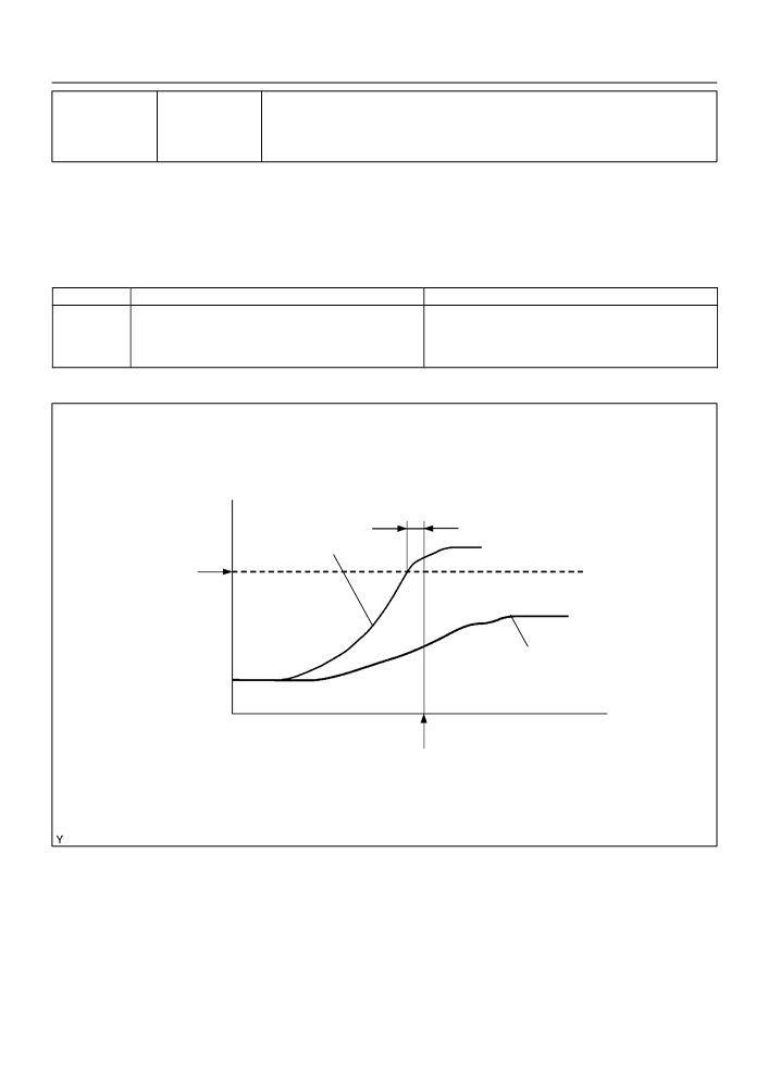
MONITOR DESCRIPTION
5 sec
Estimated ECT
Threshold
(75_C (167_F))
Indicated coolant temp. reading
ECT
Time
DTC set (after 2 driving cycle)
A82385
The ECM estimates the engine coolant temperature (ECT) based on starting temperature, engine loads, and
engine speeds. The ECM then compares the estimated ECT with the actual ECT. When the estimated ECT
reaches 75_C (167_F) the ECM checks the actual ECT. If the actual ECT is less than 75_C (167_F), the ECM
will interpret this as a fault in the thermostat or engine cooling system or thermostat and set a DTC.

05-99
DIAGNOSTICS
-
SFI SYSTEM (April, 2003)
MONITOR STRATEGY
Related DTCs
P0128
Thermostat
Main sensors
Engine coolant temperature sensor, engine cooling system, thermostat
Required sensors/components
Related sensors
Intake air temperature sensor, vehicle speed sensor
Frequency of operation
Once per drive cycle
Duration
15 minutes
MIL operation
2 driving cycles
Sequence of operation
None
TYPICAL ENABLING CONDITIONS
Specification
Item
Minimum
Maximum
The monitor will run whenever the follow-
See ”List of Disable a Monitor” (On page 05-25)
ing DTCs are not present
Battery voltage
11.0 V
-
Intake air temperature (at engine start)
-10_C (14_F)
35_C (95_F)
Engine coolant temperature
-10_C (14_F)
35_C (95_F)
(at engine start)
Engine coolant temperature - Intake air
-15_C (-27_F)
7_C (12.6_F)
temperature (at engine start)
TYPICAL MALFUNCTION THRESHOLDS
Detection Criteria
Threshold
(1) Estimated engine coolant temperature
75_C (167_F) or more
(2) Engine coolant temperature sensor output value
Less than 75_C (167_F)
Duration period of both (1) and (2)
5 seconds or more
COMPONENT OPERATING RANGE
Parameter
Standard Value
Engine coolant temperature sensor output value after
75_C (167_F) or more
warm-up
MONITOR RESULT (MODE 06 DATA)
Conversion
Test ID
Comp ID
Description of Test Data
Description of Test Limit
Unit
Factor
Difference between estimated and
actual engine coolant tempera-
Multiply
tures is calculated by ECM.
$08
$81
Malfunction criteria for thermostat
Degree C
by 0.625 and
The value stored when estimated
minus 40
coolant temperature
=75_C (167_F)
Refer to page 05-27 for the detailed information on Checking Monitor Status.
INSPECTION PROCEDURE
HINT:
Read freeze frame data using the hand−held tester or the OBD II scan tool. Freeze frame data records the
engine conditions when a malfunction is detected. When troubleshooting, it is useful for determining whether
the vehicle was running or stopped, the engine was warmed up or not, the air-fuel ratio was lean or rich,
etc. at the time of the malfunction.

05-100
DIAGNOSTICS
- SFI SYSTEM (April, 2003)
1
CHECK COOLING SYSTEM
(a) Check that there is a defect in the cooling system which causes overcool, such as abnormal radiator
fan operation, modified cooling system and so on.
NG REPAIR OR REPLACE COOLING SYSTEM
OK
2
INSPECT THERMOSTAT (See page 16-3)
NG REPLACE THERMOSTAT
(See page 16-11)
OK
3
CHECK OTHER DTC OUTPUT(IN ADDITION TO DTC P0128)
(a) Connect the hand-held tester or the OBD II scan tool to the DLC3.
(b) Turn the ignition switch ON and push the hand-held tester or the OBD II scan tool main switch ON.
(c)
Select the item ”DIAGNOSIS / ENHANCED OBD II / DTC INFO / CURRENT CODES”.
(d) Read the DTCs.
Result:
Display (DTC output)
Proceed to
P0128
A
P0128 and other DTCs
B
HINT:
If any other codes besides P0128 is output, perform the troubleshooting for those DTCs first.
B
GO TO RELEVANT DTC CHART
(See page 05-35)
A
REPLACE ECM (See page 10-11)

05-101
DIAGNOSTICS
- SFI SYSTEM (April, 2003)
05DIJ-01
DTC
P0130
OXYGEN SENSOR CIRCUIT MALFUNCTION
(BANK 1 SENSOR 1)
DTC
P2195
OXYGEN SENSOR SIGNAL STUCK LEAN
(BANK 1 SENSOR 1)
DTC
P2196
OXYGEN SENSOR SIGNAL STUCK RICH
(BANK 1 SENSOR 1)
CIRCUIT DESCRIPTION
The rear heated oxygen sensor is used to monitor oxygen concentration in the exhaust gas. For optimum
catalytic converter operation, the air fuel mixture must be maintained near the ideal ”stoichiometric” ratio.
The heated oxygen sensor output voltage changes suddenly in the vicinity of the stoichiometric ratio. The
ECM adjusts the fuel injection time so that the air-fuel ratio is nearly stoichiometric.
When the air-fuel ratio becomes LEAN, the oxygen concentration in the exhaust gas increases. And the
heated oxygen sensor informs the ECM of the LEAN condition (low voltage, i.e. less than 0.45 V).
When the air-fuel ratio is RICHER than the stoichiometric air-fuel ratio, the oxygen will be vanished from
the exhaust gas. And the heated oxygen sensor informs the ECM of the RICH condition (high voltage, i.e.
more than 0.45 V).
Ideal Air-Fuel Mixture
Heater
Solid Electrolyte
(Zirconia Element)
Platinum Electrode
Element
Cover
Richer - Air Fuel Ratio - Leaner
Air
Exhaust Gas
A
A
A-A Section
A66651
DTC No.
DTC Detection Condition
Trouble Area
Output voltage of heated oxygen sensor remains at 0.4 V or
F Open or short in heated oxygen sensor (bank 1 sensor 1)
P0130
more, or 0.5 V or less, during idling after engine is warmed up
circuit
(2 trip detection logic)
F Heated oxygen sensor (bank 1 sensor 1)
Output voltage of heated oxygen sensor remains at 0.5 V or
F Heated oxygen sensor heater (bank 1 sensor 1)
P2195
less, during idling after engine is warmed up (2 trip detection
F EFI relay
logic)
F Air induction system
Output voltage of heated oxygen sensor remains at 0.4 V or
F Fuel pressure
F Injector
P2196
more, during idling after engine is warmed up (2 trip detection
logic)
F ECM
HINT:
F
Sensor 1 refers to the sensor closest to the engine assembly.
F
The output voltage of the heated oxygen sensor and the short-term fuel trim value can be read using
the hand-held tester or the OBD ll scan tool.
05-102
DIAGNOSTICS
- SFI SYSTEM (April, 2003)
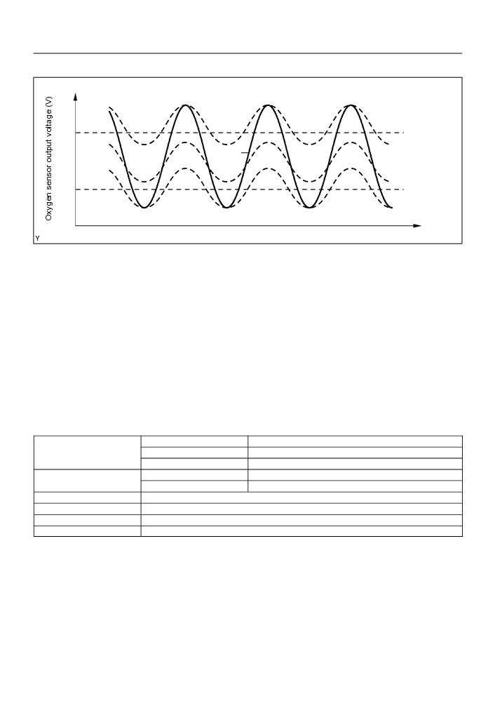
MONITOR DESCRIPTION
Rich
FAIL
0.5
PASS
FAIL
0.4
FAIL
Lean
Pass / Fail definition of voltage malfunction
Time
A85193
The engine control module (ECM) uses the heated oxygen sensor information to regulate the air-fuel ratio
near to the stoichiometric air-fuel ratio. The sensor detects oxygen levels in the exhaust gases and sends
this signal to the ECM. This maximizes the catalytic converter’s ability to purify the exhaust gases.
The heated oxygen sensor element consists of the platinum coated zirconia and heating element. The inner
surface of sensor element is exposed to the outside air, and the outer surface of sensor element is exposed
to the exhaust gases. The sensor generates between 0 V and 1 V of the voltage output in response to the
oxygen concentration in the exhaust gases. The sensor’s output voltage varies suddenly in the vicinity of
the stoichiometric air-fuel ratio.
Under normal condition, the output voltage from the heated oxygen sensor alternates between RICH and
LEAN sides periodically. When it is 0.4 V or less, the air-fuel ratio is judged as LEAN.
If the heated oxygen sensor outputs RICH signal (or LEAN signal) constantly, or if the heated oxygen sensor
cannot output enough voltage to reach the minimum specification, the ECM interprets this as a malfunction
in the heated oxygen sensor and sets a DTC.
MONITOR STRATEGY
P0130
Front heated oxygen sensor voltage is constant
Related DTCs
P2195
Front heated oxygen sensor voltage is constant at lean side
P2196
Front heated oxygen sensor voltage is constant at rich side
Main sensors
Front heated oxygen senor
Required sensors/components
Related sensors
Crank shaft position sensor, vehicle speed sensor
Frequency of operation
Once per drive cycles
Duration
18 to 36 seconds x 3
MIL operation
2 driving cycles
Sequence of operation
None

05-103
DIAGNOSTICS
-
SFI SYSTEM (April, 2003)
TYPICAL ENABLING CONDITION
Specification
Item
Minimum
Maximum
The monitor will run whenever the follow-
See ”List of Disable a Monitor” (On page 05-25)
ing DTCs are not present
There is history of following condition (a)
20 seconds (Continuously)
-
and (b) a met:
(a) Vehicle speed
25 mph (40 km/h)
-
(b) Engine speed
900 rpm
-
Time after engine start
120 seconds
-
Idle
ON
Fuel system status
Closed loop
TYPICAL MALFUNCTION THRESHOLDS
Detection Criteria
Threshold
P0130:
Sensor voltage is 0.5 V or less for 18 seconds or more
3 times or more
Sensor voltage is 0.4 V or more for 18 seconds or more
P2195:
Front heated oxygen sensor voltage is 0.5 V or less for 18
3 times or more
seconds or more
P2196:
Front heated oxygen sensor voltage is 0.4 V or more for 18
3 times or more
seconds or more
COMPONENT OPERATING RANGE
Parameter
Standard Value
In the normal condition, the heated oxygen sensor voltage
0 to 1 V
MONITOR RESULT (MODE 06 DATA)
Conversion fac-
Test ID
Comp ID
Description of test data
Description of test limit
Unit
tor
Not supported by mode $06, but
$03
-
-
-
-
by mode $05
Refer to page 05-27 for detailed information on Checking Monitor Status.
05-104
DIAGNOSTICS
-
SFI SYSTEM (April, 2003)
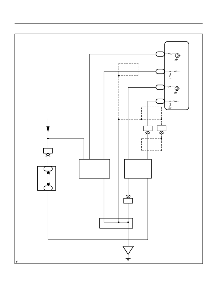
WIRING DIAGRAM
ECM
4
HT1A
P
E4
(*1)
23
OX1A
B
E4
4
HT1B
P-B
E5
P
(*1)
21
OX1B
E4
From Terminal
3 of EFI Relay
W
B
(*1)
II2
18
II2
9
BR P-B
B
W
(*1)
B
II1
6
2
1
3
2
4
B
H8
+B HT OX
HT
OX
Heated
1
4B
Oxygen
Sensor
Center
E1
E1
+B
J/B
H5
4
3
1
(Bank 1
Sensor 2)
Heated
4
4B
Oxygen
BR
Sensor
BR
(Bank 1
II2
8
Sensor 1)
B
BR
B
A
A
A
J4
A
Junction Connector
BR
*1: Shielded
EB
A84873

05-105
DIAGNOSTICS
- SFI SYSTEM (April, 2003)
CONFIRMATION DRIVING PATTERN
40 seconds
40 seconds
40 seconds
Vehicle speed
or more
or more
or more
25 mph
(40 km/h)
(d)
(d)
(d)
Idling(c)
(e)
(e)
(f)
IgnitionOFF
120 seconds
20 seconds
20 secconds
(a)(b)
30 seconds
or more
or more
or more
A85081
(a) Connect the hand-held tester to the DLC3.
(b) Switch the hand-held tester from the ”normal mode” to the ”check mode” (See page 05-11).
(c)
Start the engine and let the engine idle for 120 seconds or more.
(d) Drive the vehicle at 25 mph (40 km/h) or more for 40 seconds or more.
(e) Let the engine idle for 20 seconds or more. Perform steps (d) and (e) at least 3 times.
(f)
Let the engine idle for 30 seconds.
HINT:
If a malfunction exists, the MIL will be illuminated on the multi information display during step (f).
NOTICE:
If the conditions in this test are not strictly followed, detection of a malfunction will not occur.
If you do not have the hand-held tester, turn the ignition switch OFF after performing steps from (c)
to (f), then perform steps from (c) to (f) again.
INSPECTION PROCEDURE
HINT:
Hand-held tester only:
Narrowing down the trouble area is possible by performing ”A/F CONTROL” ACTIVE TEST (heated oxygen
sensor or other trouble areas can be distinguished).
(a) Perform ACTIVE TEST using hand-held tester (A/F CONTROL).
HINT:
”A/F CONTROL” is the ACTIVE TEST which changes the injection volume to -12.5 % or +25 %.
(1)
Connect the hand-held tester to the DLC3 on the vehicle.
(2)
Turn the ignition switch ON.
(3)
Warm up the engine by running the engine speed at 2,500 rpm for approximately 90 seconds.
(4)
Select the item ”DIAGNOSIS / ENHANCED OBD II / ACTIVE TEST / A/F CONTROL”.
(5)
Perform ”A/F CONTROL” with the engine in an idle condition (press the right or left button).
Result:
Heated oxygen sensor reacts in accordance with increase and decrease of injection volume
+25 % rich output: More than 0.5 V,
-12.5 % lean output: Less than 0.4 V