Toyota Corolla (2004+). Manual - part 18

30-2
DRIVE SHAFT / PROPELLER SHAFT
- DRIVE SHAFT, PROPELLER SHAFT, AXLE
300A0-02
ON-VEHICLE INSPECTION
1.
INSPECT FRONT AXLE HUB BEARING
(a) Remove the front wheel.
(b) Separate the front disc brake caliper assy
(See page 30-17).
(c)
Remove the front disc.
(d) Inspect the bearing backlash.
(1)
Using a dial indicator, check the backlash near the
center of the axle hub.
Maximum: 0.05 mm (0.0020 in.)
If the backlash exceeds the maximum, replace the front axle
hub bearing.
D26919
(e) Inspect the axle hub deviation.
(1)
Using a dial indicator, check the deviation at the sur-
face of the axle hub outside the hub bolt.
Maximum: 0.05 mm (0.0020 in.)
If the backlash exceeds the maximum, replace the front axle
hub sub-assy.
(f)
Install the front disc.
(g) Install the front disc brake caliper assy
D26920
(See page 30-17).
(h) Install the front wheel.
Torque: 103 N m (1,050 kgf cm, 76 ft lbf)
2.
INSPECT REAR AXLE HUB BEARING
(a) Remove the rear wheel.
(b) Remove rear brake drum sub-assy.
(c)
Inspect the bearing backlash.
(1)
Set a dial indicator near the center of the axle hub
and check the backlash in the bearing shaft sirec-
tion.
Maximum: 0.05 mm (0.0020 in.)
If the backlash exceeds the maximum, replace the rear axle hub
& bearing assy.
D26921

30-3
DRIVE SHAFT / PROPELLER SHAFT
- DRIVE SHAFT, PROPELLER SHAFT, AXLE
(d) Inspect the axle hub deviation.
(1)
Using a dial indicator, check the deviation at the sur-
face of the axle hub outside the hub bolt.
Maximum: 0.07 mm (0.0028 in.)
If the backlash exceeds the maximum, replace the rear axle hub
& bearing assy.
(e) Install the rear brake drum sub-assy.
(f)
Install the rear wheel.
D26922
Torque: 103 N m (1,050 kgf cm, 76 ft lbf)

30-26
DRIVE SHAFT / PROPELLER SHAFT
- REAR AXLE LH HUB BOLT
REAR AXLE LH HUB BOLT
300A8-02
REPLACEMENT
HINT:
COMPONENTS: See page 30-23
1.
REMOVE REAR WHEEL
2.
REMOVE REAR BRAKE DRUM SUB-ASSY
3.
REMOVE REAR AXLE LH HUB BOLT
SST
(a) Using SST and a hammer handle or an equivalent, re-
move the LH hub bolt.
SST
09628-10011
Hold
Turn
D26928
4.
INSTALL REAR AXLE LH HUB BOLT
(a) Install a washer and nut to a new LH hub bolt as shown
in the illustration.
Washer
(b) Using a hammer handle or an equivalent to hold the rear
Nut
axle hub & bearing assy LH, install the LH hub bolt by
tightening the nut.
Hold
Turn
D26929
5.
INSTALL REAR BRAKE DRUM SUB-ASSY
6.
INSTALL REAR WHEEL
Torque: 103 N m (1,050 kgf cm, 76 ft lbf)

30-23
DRIVE SHAFT / PROPELLER SHAFT
- REAR AXLE HUB & BEARING ASSY LH
REAR AXLE HUB & BEARING ASSY LH
300A6-02
COMPONENTS
w/ ABS:
Skid Control
Sensor Wire
F Rear Axle LH Hub Bolt
Rear Brake Drum Sub-assy
61 (622, 45)
x4
Rear Axle Hub & Bearing Assy LH
Nm (kgfcm, ftlbf)
: Spedified torque
F Non-reusable parts
D26927

30-24
DRIVE SHAFT / PROPELLER SHAFT
- REAR AXLE HUB & BEARING ASSY LH
300A7-03
REPLACEMENT
HINT:
COMPONENTS: See page 30-23
1.
REMOVE REAR WHEEL
2.
REMOVE REAR BRAKE DRUM SUB-ASSY
3.
DISCONNECT SKID CONTROL SENSOR WIRE (W/ ABS)
4.
REMOVE REAR AXLE HUB & BEARING ASSY LH
(a) Remove the 4 bolts and hub & bearing assy LH.
C66800
5.
INSTALL REAR AXLE HUB & BEARING ASSY LH
(a) Install the hub & bearing assy LH with the 4 bolts.
Torque: 61 N m (622 kgf cm, 45 ft lbf)
C66800
6.
CONNECT SKID CONTROL SENSOR WIRE (W/ ABS)
7.
INSPECT BEARING BACKLASH
(a) Set a dial indicator near the center of the axle hub and
check the backlash in the bearing shaft sirection.
Maximum: 0.05 mm (0.0020 in.)
If the backlash exceeds the maximum, replace the rear axle hub
& bearing assy LH.
D26921

30-25
DRIVE SHAFT / PROPELLER SHAFT
- REAR AXLE HUB & BEARING ASSY LH
8.
INSPECT AXLE HUB DEVIATION
(a) Using a dial indicator, check the deviation at the surface
of the axle hub outside the hub bolt.
Maximum: 0.07 mm (0.0028 in.)
If the backlash exceeds the maximum, replace the rear axle hub
& bearing assy LH.
D26922
9.
INSTALL REAR BRAKE DRUM SUB-ASSY
10. INSTALL REAR WHEEL
Torque: 103 N m (1,050 kgf cm, 76 ft lbf)
11. CHECK ABS SPEED SENSOR SIGNAL (W/ ABS) (See page
05-297)

30-1
DRIVE SHAFT / PROPELLER SHAFT
- DRIVE SHAFT, PROPELLER SHAFT, AXLE
DRIVE SHAFT, PROPELLER SHAFT, AXLE
3009Z-03
PROBLEM SYMPTOMS TABLE
Use the table below to help you find the cause of the problem. The numbers indicate the priority of
the likely cause of the problem. Check each part in order. If necessary, replace these parts.
Symptom
Suspect Area
See page
5. Wheel alignment
26-5
27-3
6. Steering linkage (Loosen or worn)
51-18
Wander
7. Hub bearing (Worn)
30-17
30-24
8. Stabilizer bar
26-19
1. Wheel balance
2. Shock absorber
26-8
3. Suspension arm lower (Worn)
26-13
Front wheel shimmy
4. Coil spring
26-8
5. Hub bearing (Worn)
30-17
30-24
1. Inbord joint (Worn)
30-6
Noise (Drive shaft)
2. Outbord joint (Worn)
30-6
32-40
BRAKE
- BRAKE ACTUATOR ASSY
BRAKE ACTUATOR ASSY
320IO-01
ON-VEHICLE INSPECTION
1.
CONNECT HAND-HELD TESTER:
(a) Connect the hand-held tester to the DLC3.
(b) Start the engine and run it at idle.
(c)
Select the ACTIVE TEST mode on the hand-held tester.
HINT:
Please refer to the hand-held tester operator’s manual for further details.
2.
INSPECT ACTUATOR MOTOR OPERATION
(a) With the motor relay ON, check the actuator motor operation noise.
(b) Turn the motor relay to OFF.
(c)
Depress the brake pedal and hold it for about 15 seconds. Check that the brake pedal cannot be de-
pressed.
(d) With the motor relay ON, check that the pedal does not pulsate.
NOTICE:
Do not keep motor relay ON for more than 5 seconds continuously. When operating it continuously,
set the interval more than 20 seconds.
(e) Turn the motor relay to OFF and release the brake pedal.
3.
INSPECT RIGHT FRONT WHEEL OPERATION
NOTICE:
Never turn ON the solenoid which is not described below.
(a) With the brake pedal depressed, perform the following operations.
(b) Turn the SFRH and SFRR solenoid to ON simultaneously, and check that the pedal cannot be de-
pressed.
NOTICE:
Do not keep solenoid ON for more than 10 seconds continuously. When operating it continuously,
set the interval more than 20 seconds.
(c)
Turn the SFRH and SFRR solenoid to OFF simultaneously, and check that the pedal can be de-
pressed.
(d) Turn the motor relay to ON, and check that the pedal returns.
NOTICE:
Do not keep motor relay ON for more than 5 seconds continuously. When operating it continuously,
set the interval more than 20 seconds.
(e) Turn the motor relay to OFF and release the brake pedal.
4.
INSPECT OTHER WHEEL OPERATION
(a) As the same procedure, check the solenoids of other wheels.
HINT:
Left front wheel: SFLH, SFLR
Right rear wheel: SRRH, SRRR
Left rear wheel: SRLH, SRLR

32-41
BRAKE
- BRAKE ACTUATOR ASSY
320IP-04
REPLACEMENT
1.
DRAIN BRAKE FLUID
NOTICE:
Wash the brake fluid off immediately if it comes into contact with any painted surface.
2.
REMOVE FRONT WHEEL RH
3.
REMOVE FRONT FENDER LINER RH
4.
REMOVE BRAKE ACTUATOR WITH BRACKET
(a) Turn the latch of the actuator connector to disconnect the
connector.
(b) Using SST, disconnect the 6 brake tubes from the brake
actuator.
SST
09023-00100
F42822
(c)
Attach tags or make a memo to identify the place to recon-
To Master Cylinder
nect.
To Master
To Front Left
Cylinder
To Rear Right
To Front Right
To Rear Left
F42823

32-42
BRAKE
- BRAKE ACTUATOR ASSY
(d) Remove the nut, 2 bolts and brake actuator with bracket.
F42824
5.
REMOVE BRAKE ACTUATOR ASSY
(a) Remove the 3 nuts and brake actuator from bracket.
6.
INSTALL BRAKE ACTUATOR ASSY
(a) Install the brake actuator with the 3 nuts to the bracket.
Torque: 4.7 N m (48 kgf cm, 42 in. lbf)
7.
INSTALL BRAKE ACTUATOR WITH BRACKET
(a) Install the brake actuator with bracket with the nut and 2
bolts.
Torque: 19 N m (194 kgf cm, 14 ft lbf)
F42824

32-43
BRAKE
- BRAKE ACTUATOR ASSY
(b) Using SST, connect the 6 brake tubes to the correct posi-
To Master Cylinder
tion of brake actuator, as shown in the illustration.
To Master
To Front Left
SST
09023-00100
Cylinder
Torque: 15.2 N m (155 kgf cm, 11 ft lbf)
(c)
Connect the brake actuator connector.
To Rear Right
To Front Right
To Rear Left
F42823
8.
INSTALL FRONT FENDER LINER RH
9.
INSTALL FRONT WHEEL RH
Torque: 103 N m (1,050 kgf cm, 76 ft lbf)
10. FILL RESERVOIR WITH BRAKE FLUID
11. BLEED MASTER CYLINDER (See page 32-4)
SST
09023-00100
12. BLEED BRAKE LINE (See page
32-4)
13. CHECK FLUID LEVEL IN RESERVOIR
14. CHECK BRAKE FLUID LEAKAGE
15. CHECK BRAKE ACTUATOR WITH HAND-HELD TESTER (See page
05-297)

32-19
BRAKE
- BRAKE BOOSTER ASSY
320IG-01
COMPONENTS
w/ Cruse control:
12.7 (130, 9)
Clevis Pin
Cruise Control Actuator
FGasket
Wave Washer
43 (438, 32)
Clip
Brake Tube Clamp
Clevis
43 (438, 32)
Vacuum Hose
w/ ABS:
Level
Clip
No.1 Way
Grommet
Warning Switch
Connector
15.2 (155, 11)
Vacuum Check Valve
15.2 (155, 11)
15.2 (155, 11)
26 (265, 19)
Vacuum Check
Brake Master
Valve Bracket
Cylinder Sub-assy
12.5 (127, 9)
M/T:
No.1 Way
Brake Booster Assy
Clip
15.2 (155, 11)
M/T:
Clutch Reservoir
Tube No.1
Air Cleaner
Cap Sub-assy
Brake Tube
Air Cleaner
Element
15.2 (155, 11)
Air Cleaner Case Sub-assy
N·m (kgf·cm, ft·lbf)
: Specified toque
F Non-reusable part
Lithium soap base glycol grease
F42812
32-18
BRAKE
- BRAKE BOOSTER ASSY
BRAKE BOOSTER ASSY
320IF-01
ON-VEHICLE INSPECTION
1.
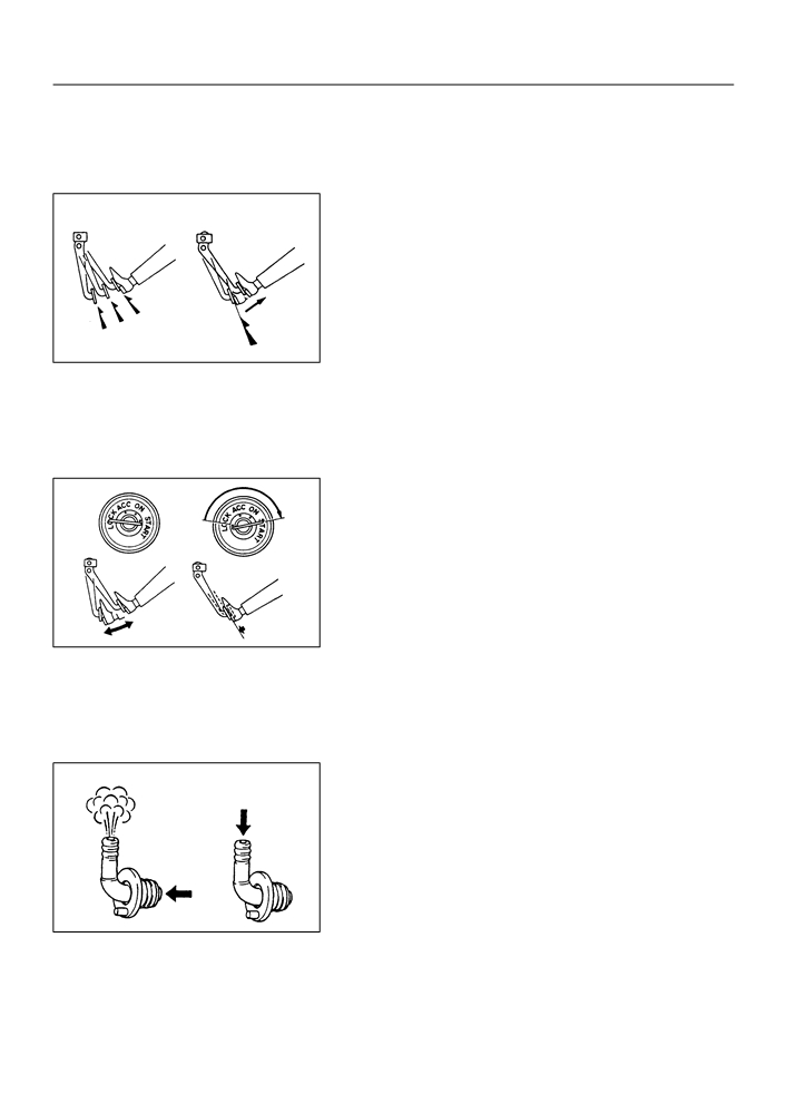
INSPECT BRAKE BOOSTER
GOOD
NO GOOD
(a) Airtightness check.
(1)
Start the engine and stop it after 1 or 2 minutes. De-
press the brake pedal several times slowly.
HINT:
If the pedal goes down farthest at the 1st time, but gradually
rises after the 2nd or 3rd time, the booster is airtight.
3rd
2nd
(2)
Depress the brake pedal while the engine is run-
1st
BR2238
ning, and stop the engine with the pedal depressed.
HINT:
If there is no change in the pedal reserve distance after holding
the pedal for 30 seconds, the booster is airtight.
(b) Operating check.
(1)
Depress the brake pedal several times with the igni-
tion switch OFF and check that there is no change
in the pedal reserve distance.
(2)
Depress the brake pedal and start the engine.
HINT:
If the pedal goes down slightly, operation is normal.
2.
INSPECT VACUUM CHECK VALVE
BR2237
(a) Check vacuum check valve.
(1)
Slide the clip and disconnect the vacuum hose.
(2)
Remove the vacuum check valve.
(3)
Check that there is ventilation from the booster to
Ventilation
No Ventilation
engine, and no ventilation from the engine to the
booster.
(4)
If any fault is found, replace the vacuum check
valve.
F40007

32-20
BRAKE
- BRAKE BOOSTER ASSY
320IH-02
REPLACEMENT
1.
DRAIN BRAKE FLUID
NOTICE:
Wash the brake fluid off immediately if it comes into contact with any painted surface.
2.
REMOVE AIR CLEANER CAP SUB-ASSY
3.
REMOVE AIR CLEANER CASE SUB-ASSY
(a) Remove the air cleaner element, then remove the 3 bolts and air cleaner case sub-assy.
4.
REMOVE BRAKE MASTER CYLINDER SUB-ASSY (See page 32-13)
5.
DISCONNECT BRAKE MASTER CYLINDER PUSH ROD CLEVIS
(a) Loosen the push rod clevis lock nut.
(b) Remove the clip, clevis pin and wave washer.
6.
REMOVE CRUISE CONTROL ACTUATOR ASSY (W/
CRUISE CONTROL)
(a) Remove the 2 nuts and bolt from the cruise control actua-
tor and bracket, and move cruise control actuator aside.
F42813
7.
REMOVE FRONT WHEEL LH
8.
REMOVE BRAKE BOOSTER ASSY
(a) Using SST and spanner, disconnect the brake tube from
the flexible hose, and remove the brake tube from the
body.
SST
09023-00100
(b) Slide the clip, disconnect the vacuum hose from the brake
booster assy.
F40019

32-21
BRAKE
- BRAKE BOOSTER ASSY
(c)
Disconnect the 2 or 3 brake tubes from the clamp, and
w/o ABS:
move brake tubes aside.
w/ ABS:
F42814
(d) Remove the 4 nuts and clevis.
(e) Pull out the brake booster and gasket.
9.
INSTALL BRAKE BOOSTER ASSY
(a) Install the clevis to the booster push rod.
F42862
(b) Install a new gasket and brake booster with the 4 nuts.
Torque: 12.7 N m (130 kgf cm, 9 ft lbf)
F42862