Toyota Corolla (2004+). Manual - part 19
32-22
BRAKE
- BRAKE BOOSTER ASSY
(c)
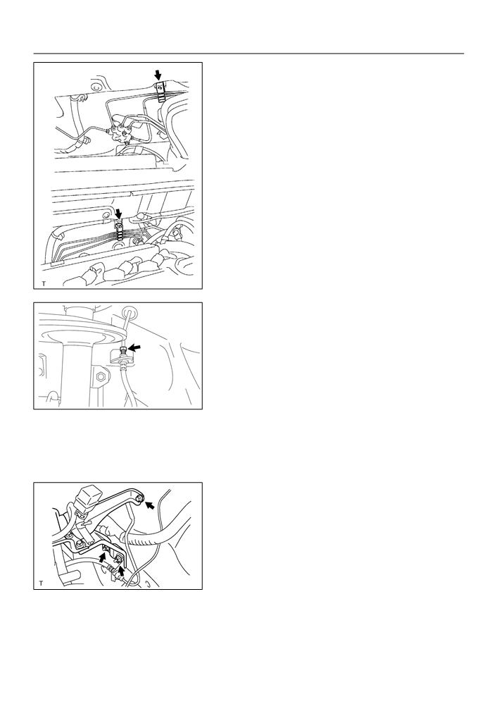
Connect the 2 or 3 brake tubes to the clamp.
w/o ABS:
(d) Connect the vacuum hose to the brake booster.
w/ ABS:
F42814
(e) Using SST and spanner, connect the brake tube to the
flexible hose.
SST
09023-00100
Torque: 15.2 N m (155 kgf cm, 11 ft lbf)
F40019
10. INSTALL FRONT WHEEL LH
Torque: 103 N m (1,050 kgf cm, 76 ft lbf)
11. INSTALL CRUISE CONTROL ACTUATOR ASSY (W/
CRUISE CONTROL)
(a) Install the cruise control actuator and bracket with 2 nuts
and bolt.
Torque: 43 N m (438 kgf cm, 32 ft lbf)
F42813
12. CONNECT BRAKE MASTER CYLINDER PUSH ROD CLEVIS
(a) Apply the lithium soap base glycol grease to the push rod clevis pin.
(b) Connect the brake master cylinder push rod clevis with the push rod clevis pin, wave washer and clip.
13. INSTALL BRAKE MASTER CYLINDER SUB-ASSY (See page
32-13)
32-23
BRAKE
-
BRAKE BOOSTER ASSY
14. INSTALL AIR CLEANER CASE SUB-ASSY
(a) Install the air cleaner case with 3 bolts, then install the air cleaner element to the air cleaner case sub-
assy.
15. INSTALL AIR CLEANER CAP SUB-ASSY
16. FILL RESERVOIR WITH BRAKE FLUID
17. BLEED MASTER CYLINDER (See page 32-4)
SST
09023-00100
18. BLEED BRAKE LINE (See page
32-4)
19. CHECK AND ADJUST BRAKE PEDAL HEIGHT (See page
32-6)
20. CHECK PEDAL FREE PLAY (See page 32-6)
21. CHECK PEDAL RESERVE DISTANCE (See page 32-6)
22. CHECK FLUID LEVEL IN RESERVOIR
23. CHECK BRAKE FLUID LEAKAGE

32-11
BRAKE
- BRAKE MASTER CYLINDER SUB-ASSY (April, 2003)
BRAKE MASTER CYLINDER SUB-ASSY (April, 2003)
320ZN-01
COMPONENTS
w/ ABS:
No.1 Way
15.2 (155, 11)
Brake Fluid Level
Switch Connector
Brake Booster Assy
Brake Master Cylinder
Sub-assy
15.2 (155, 11)
15.2 (155, 11)
Vacuum Check
Valve Bracket
No.1 Way
M/T:
Clip
15.2 (155, 11)
M/T:
12.5 (127, 9)
Clutch Reservoir
Tube No.1
15.2 (155, 11)
Air Cleaner Cap Sub-assy
N·m (kgf·cm, ft·lbf)
: Specified torque
C86271

32-12
BRAKE
- BRAKE MASTER CYLINDER SUB-ASSY (April, 2003)
A/T:
Master Cylinder
Reservoir Sub-assy
Cap
Strainer
Master Cylinder
Reservoir Sub-assy
Grommet
F
O-Ring
Grommet
Master Cylinder
F
Gasket
F
Piston Stopper Bolt
Snap Ring
10 (102, 7)
Reservoir Stopper Screw
1.8 (18.4, 15.9 in.·lbf)
No. 1 Piston Sub-assy
No. 2 Piston Sub-assy
: Specified torque
N·m (kgf·cm, ft·lbf)
F Non-reusable part
Lithium soap base glycol grease
C86272

32-13
BRAKE
- BRAKE MASTER CYLINDER SUB-ASSY (April, 2003)
320IE-02
OVERHAUL
1.
DRAIN BRAKE FLUID
NOTICE:
Wash the brake fluid off immediately if it comes into contact with any painted surface.
2.
REMOVE AIR CLEANER CAP SUB-ASSY
3.
REMOVE BRAKE MASTER CYLINDER SUB-ASSY
(a) Disconnect the brake fluid level switch connector from
master cylinder reservoir sub-assy.
(b) M/T:
Slide the clip and disconnect the clutch reservoir tube
No.1 from master cylinder reservoir sub-assy.
(c)
Using SST, disconnect the 2 brake tubes from the master
cylinder.
SST
09023-00100
SST
F42809
(d) Using SST, disconnect the 2 or 3 brake tubes from the
w/o ABS:
No.1 way.
SST
09023-00100
w/ ABS:
F42810

32-14
BRAKE
- BRAKE MASTER CYLINDER SUB-ASSY (April, 2003)
(e) Remove the 2 nuts, and pull out the master cylinder, No.1
way and vacuum check valve bracket.
F42811
4.
REMOVE BRAKE MASTER CYLINDER RESERVOIR SUB-ASSY
(a) Remove the reservoir stopper screw and master cylinder reservoir sub-assy.
(b) Remove the 2 cylinder reservoir grommets.
5.
REMOVE BRAKE MASTER CYLINDER KIT
(a) Hold the master cylinder in the vise with the 2 aluminum
plates in between.
(b) Remove the O-ring.
(c)
Push in the piston and remove the snap ring with snap
ring pliers.
F40004
(d) Push in the piston and remove the piston stopper bolt and
gasket.
(e) Remove the No.1 piston sub-assy by hand, pulling
straight out not at an angle.
NOTICE:
If being pulled out at an angle, the piston may damage the
cylinder bore.
C69097
(f)
Place a cloth and 2 wooden blocks on the work table and
lightly edges until the No.2 piston sub-assy drops out of
the cylinder.
NOTICE:
If being pulled out at an angle, the piston may damage the
cylinder bore.
HINT:
(A)
Make sure that the distance (A) from the cloth to the top of the
R12236
blocks is at least 100 mm (3.94 in.).

32-15
BRAKE
- BRAKE MASTER CYLINDER SUB-ASSY (April, 2003)
6.
INSPECT BRAKE MASTER CYLINDER
(a)
Check the cylinder bore for rust or scoring.
7.
INSTALL BRAKE MASTER CYLINDER KIT
(a) Hold the master cylinder in the vise with the 2 aluminum
plates in between.
(b) Apply the lithium soap base glycol grease to the No.1 and
No.2 piston sub-assy.
(c)
Install the No.2 and No.1 piston sub-assy to the master
cylinder.
NOTICE:
F
If being inserted at an angle, the piston may damage
the cylinder bore.
F
Be careful not to damage the rubber lips on the pis-
tons.
(d) Push in the piston and install a new gasket and a new pis-
ton stopper bolt.
Torque: 10 N m (102 kgf cm, 7 ft lbf)
C69097
(e) Push in the piston and install the snap ring with snap ring
pliers.
(f)
Apply the lithium soap base glycol grease to a new O-
ring, and install the O-ring to the master cylinder.
F40004
8.
INSTALL BRAKE MASTER CYLINDER RESERVOIR SUB-ASSY
(a) Apply the lithium soap base glycol grease to 2 brake master cylinder reservoir grommets.
(b) Install the master cylinder reservoir with the screw.
Torque: 1.8 N m (18.4 kgf cm, 15.9 in. lbf)
9.
INSPECT AND ADJUST B RAKE BOOSTER PUSH
ROD
SST
(a) Apply the chalk to the flat surfaced tip of the SST pin.
(b) Set SST on the master cylinder and lower the pin of the
SST until it slightly touches the piston.
SST
09737-00013
C94955
F42864

32-16
BRAKE
- BRAKE MASTER CYLINDER SUB-ASSY (April, 2003)
(c)
Turn SST upside down and place it on the brake booster.
SST
SST
09737-00013
Clearance: 0 mm (0 in.)
HINT:
F
If there is a space between the SST main body and the
booster shell (chalk is applied to the booster push rod), it
means that the clearance is too small.
F
If chalk is not applied to the booster push rod after placing
SST
F42815
the SST on the brake booster, it means that the clearance
is too large.
(d) If clearance is outside of the specified range, fix the push
rod using SST and adjust the length of the protruding ad-
justing bolt.
SST
09737-00020
HINT:
When adjusting the push rod, depress the brake pedal suffi-
ciently so that the push rod sticks out.
SST
F42816
10. INSTALL BRAKE MASTER CYLINDER SUB-ASSY
(a) Install the master cylinder, No.1 way and vacuum check
valve bracket with the 2 nuts.
Torque: 12.5 N m (127 kgf cm, 9 ft lbf)
F42811
(b) Using SST, connect the 2 or 3 brake tubes to the No.1
w/o ABS:
way.
SST
09023-00100
Torque: 15.2 N m (155 kgf cm, 11 ft lbf)
w/ ABS:
F42810

32-17
BRAKE
- BRAKE MASTER CYLINDER SUB-ASSY (April, 2003)
(c)
Using SST, connect the 2 brake tubes to the master cylin-
der.
SST
09023-00100
Torque: 15.2 N m (155 kgf cm, 11 ft lbf)
(d) M/T:
Connect the clutch reservoir tube No.1 with the clip to
master cylinder reservoir sub-assy.
(e) Connect the brake fluid level switch connector to master
SST
F42809
cylinder reservoir sub-assy.
11. INSTALL AIR CLEANER CAP SUB-ASSY
12. FILL RESERVOIR WITH BRAKE FLUID
13. BLEED MASTER CYLINDER (See page 32-4)
SST
09023-00100
14. BLEED BRAKE LINE (See page
32-4)
15. CHECK FLUID LEVEL IN RESERVOIR
16. CHECK BRAKE FLUID LEAKAGE

32-6
BRAKE
- BRAKE PEDAL SUB-ASSY
BRAKE PEDAL SUB-ASSY
320IA-01
ADJUSTMENT
1.
CHECK AND ADJUST BRAKE PEDAL HEIGHT
Stop Lamp Switch
(a)
Inspect brake pedal height.
Pedal height from asphalt sheet:
M/T: 134.9 - 144.9 mm (5.311 - 5.703 in.)
A/T: 136.0 - 146.0 mm (5.353 - 5.747 in.)
(1)
Disconnect the connector from the stop lamp
switch.
(2)
Remove the stop lamp switch.
(3)
Loosen the clevis lock nut.
(4)
Adjust the pedal height by turning the pedal push
rod.
Push Rod
(5)
Tighten the push rod lock nut.
Torque: 26 N m (265 kgf cm, 19 ft lbf)
(6)
Install the stop lamp switch.
(7)
Connect the connector to the stop lamp switch.
(8)
Push the brake pedal in 5 - 15 mm (0.20 - 0.59 in.),
Pedal Height
and turn the stop lamp switch to lock the nut in the
position where the stop lamp goes off.
F40001
(9)
After installation, push the brake pedal in 5 - 15 mm
(0.20 - 0.59 in.), check that stop lamp comes on.
2.
CHECK PEDAL FREE PLAY
(a)
Stop the engine and depress the brake pedal several
times until there is no more vacuum left in the booster.
(b)
Push in the pedal until the beginning of the resistance is
felt. Measure the distance, as shown in the installation.
Pedal free play: 1 - 6 mm (0.04 - 0.24 in.)
If incorrect, check the stop lamp switch clearance.
If the clearance is OK, then troubleshoot the brake system.
Stop lamp switch clearance:
0.5 - 2.4 mm (0.020 - 0.094 in.)
Pedal Free Play
F40002

32-7
BRAKE
- BRAKE PEDAL SUB-ASSY
3.
CHECK PEDAL RESERVE DISTANCE
(a) Release the parking brake lever.
With engine running, depress the pedal and measure the
pedal reserve distance, as shown in the installation.
Pedal reserve distance from asphalt sheet at 490 N
(50 kgf, 110.2 lbf): More than 70 mm (2.76 in.)
If incorrect, troubleshoot the brake system.
Pedal Reserve
Distance
R00934

32-8
BRAKE
- BRAKE PEDAL SUB-ASSY
320IB-01
COMPONENTS
Meter Hood Sub-assy
Combination Meter Assembly
23.6 (240, 17)
Brake Pedal
Stop Lamp Switch Connector
Support Sub-assy
Stop Lamp Switch Assy
F Bush
36.8 (375, 27)
F Bush
12.7 (130, 9)
Push Rod Clevis Pin
Wave Washer
Brake Pedal Sub-assy
Brake Master Cylinder
Push Rod Clevis
A/T:
Clip
Brake Pedal Sub-assy
Brake Pedal Pad
Brake Pedal Pad
N·m (kgf·cm, ft·lbf)
: Specified torque
F Non-reusable part
Lithium soap base glycol grease
F42828

32-9
BRAKE
- BRAKE PEDAL SUB-ASSY
320IC-01
REPLACEMENT
1.
REMOVE COMBINATION METER ASSEMBLY (See page 71-17)
2.
DISCONNECT BRAKE MASTER CYLINDER PUSH ROD CLEVIS
(a) Remove the clip and push rod clevis pin and wave washer, and disconnect the push rod clevis from
the brake pedal.
3.
REMOVE BRAKE PEDAL SUPPORT SUB-ASSY
(a) Remove the bolt from the brake pedal support.
(b) Disconnect the stop lamp switch connector.
F42280
(c)
Remove the 4 nuts and brake pedal support assy.
F42862
4.
REMOVE BRAKE PEDAL SUB-ASSY
(a) Remove the bolt and nut from the brake pedal support sub-assy.
(b) Remove the brake pedal sub-assy and 2 bushes.
5.
REMOVE STOP LAMP SWITCH ASSY
(a) Loosen the stop lamp switch lock nut.
(b) Remove the stop lamp switch assy from the brake pedal support sub-assy.
6.
REMOVE BRAKE PEDAL PAD
(a) Remove the brake pedal pad from the brake pedal sub-assy.
7.
INSTALL BRAKE PEDAL PAD
(a) Install the brake pedal pad to the brake pedal sub-assy.
8.
INSTALL STOP LAMP SWITCH ASSY
(a) Install the stop lamp switch assy to the brake pedal sub-assy.
9.
INSTALL BRAKE PEDAL SUB-ASSY
(a) Apply the lithium soap base glycol grease to the 2 new bushes on the ends and sides.
(b) Install the brake pedal sub-assy and 2 bushes to the brake pedal support with the bolt and nut.
Torque: 36.8 N m (375 kgf cm, 27 ft lbf)

32-10
BRAKE
- BRAKE PEDAL SUB-ASSY
10. INSTALL BRAKE PEDAL SUPPORT SUB-ASSY
(a) Install the brake pedal support assy with the 4 nuts.
Torque: 12.7 N m (130 kgf cm, 9 ft lbf)
(b) Connect the stop lamp switch connector to the stop lamp
switch assy.
F42862
(c)
Install the bolt to the brake pedal support sub-assy.
Torque: 23.6 N m (240 kgf cm, 17 ft lbf)
F42280
11. CONNECT BRAKE MASTER CYLINDER PUSH ROD CLEVIS
(a) Apply the lithium soap base glycol grease to the push rod clevis pin.
(b) Connect the brake master cylinder push rod clevis with the push rod clevis pin, wave washer and clip.
12. INSTALL COMBINATION METER ASSEMBLY
13. CHECK AND ADJUST BRAKE PEDAL HEIGHT (See page
32-6)
14. CHECK PEDAL FREE PLAY (See page 32-6)
15. CHECK PEDAL RESERVE DISTANCE (See page 32-6)

32-4
BRAKE
- BRAKE FLUID
BRAKE FLUID
320I9-01
BLEEDING
NOTICE:
Wash the brake fluid off immediately if it comes into contact with any painted surface.
HINT:
If any work is done on the brake system or if air in the brake lines is suspected, bleed the air from the system.
1.
FILL RESERVOIR WITH BRAKE FLUID
Fluid: SAE J1703 or FMVSS No. 116 DOT3
C80823
2.
BLEED MASTER CYLINDER
HINT:
If the master cylinder has been disassembled or if the reservoir
becomes empty, bleed the air from the master cylinder.
(a) Disconnect the brake lines from the master cylinder.
SST
09023-00100
(b) Slowly depress the brake pedal and hold it.
C80824
(c)
Block off the outer holes with your fingers, and release the
brake pedal.
(d) Repeat (b) and (c) 3 or 4 times.
F42863
3.
BLEED BRAKE LINE
(a) Connect the vinyl tube to the brake caliper.
(b) Depress the brake pedal several times, then loosen the
bleeder plug with the pedal held down.
(c)
At the point when fluid stops coming out, tighten the
bleeder plug, then release the brake pedal.
Torque: 8.3 N m (85 kgf cm, 74 in. lbf)
(d) Repeat (b) and (c) until all the air in the fluid has been bled
C80826
out.