Dacia Pick-Up 1304/1305/1307. Service manual - part 132


  Index      Dacia     Dacia Pick-Up 1304/1305/1307 (Engine F8Q) - service and repair manual 2004 year


Search            


Content   ..  130  131  132  133   ..


Dacia Pick-Up 1304/1305/1307. Service manual - part 132


HORN - ENGINE IMMOBILISER

82

ATTENTION !

These operations must be performed only when the UCE anti starting is not in stand

by state.

The maximum number of electronic keys which can be re-programmed for a vehicle

is maximum 4; so, if the two original electronic keys of the vehicles have been lost or
have been defected, only maximum two other electronic keys may be re-programmed.

82 - 4

ELECTRONIC KEYS PROGRAMMING PROCEDURE

ELECTRONIC KEYS PROGRAMMING PROCEDURE

This is to be applied when the replacement of the electronic keys is needed and the procedure is

as follows:

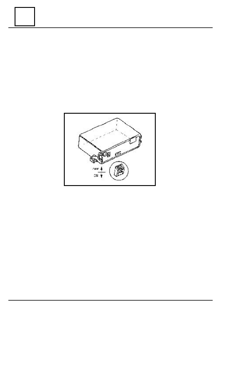
- bring the switch (1) of the UCE anti starting in position “ON”;
- place the end of the first electronic key in contact with the anti starting receiver;
- after one second, place the end of the second electronic key in contact with the anti starting

receiver;

- bring the switch (1) of the anti starting UCE  to the position “OFF“;
- check using both electronic keys the good operation of the anti starting.

83

INSTRUMENT PANEL

83 - 1

 INSTRUMENTS PANEL - SERIES 5136 ( SÃCELE )

INSTRUMENT PANEL

83

83 - 2

The instruments panel dismounting does not imply dashboard dismounting.

D

ISMO UNTING

Disconnect the battery.
Disconnect the speedometer cable from the instruments panel.
Disconnect connectors from the instruments panel. (1, 2 and 3).
Disconnect connectors of the switches from the instruments panel.
Dimounting the cable of tachometer, by realising, at the back of the panel instrument.
Dimounting the timer of windscreen wipers windscreen.
Dimounting  the control reglage fhares.
Dimounting thouse four  screws which fix the frame fixation device: two are  situated in front

of the picture, two are under the ashtray of panel instrument.

Remove the frame fixation device, on which is the panel instrument.
Kick away both lateral clips (4 ) which fix the panel instrument to the panel instrument.
Take out the instruments panel.

R

EMOUNTING

Perform in reverse order the dismounting operations.

REPLACEMENT OF INSTRUMENT PANEL

( for vehicles made after 02.04.2003)

1

2

3

4

83

INSTRUMENT PANEL

83 - 3

CONNECTOR B

1.

 Hand brake warning light

2

. Choke warning light

3

. Battery charging warning light or fog projector

4

. Rear window heating warning light

5

. Dashboard lighting

6

. Braking system failure warning lamp or wear brake pads warning lamp

CONNECTOR C

1

. Supply ( + DC ) after contact switch

2

. Oil pressure gauge

3

. Oil pressure warning light

4

.  Mass ( - )

5

. Turn signal lights

6

. Fuel level indicator

7

. Water temperature warning light

8

. Temperature indicator warning light

9

. Low fuel level warning light

Subject to the vehicle equipping status, the function of some indicators shall be modified as

follows :

CONNECTOR A

1

. Hazard warning light

2

. Headlight main beam warning light

3

. Side lights warning light

4

. Mass ( - )

5

. Revolutions counter (RPM)

6

. Supply ( + DC ) after contact switch

7

. Fog lights warning light

8

. Mass

Connectors disposal – front view of instruments panel:

CONNECTORS - SERIES 5136 ( SÃCELE )


Content   ..  130  131  132  133   ..