Dacia Pick-Up 1304/1305/1307. Service manual - part 133
INSTRUMENT PANEL
83
83 - 4
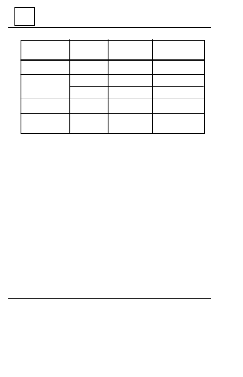
V
EHICLE
P
O SITION
I
NITIAL
B
ECO MING
EQUIPMENT
IN
CO NNECTOR
B
4x2 BOSCH
injection
4x4 BOSCH
injection
Carburetor
4x4
Standard equipment
2
2
4
4
3
Choke warning light
Choke warning light
Rear window heating
light
Defrost field glass
indicator
Battery charging light
Fuel injection warning
light
Fuel injection warning
light
4x4 coupling warning
light
4x4 coupling warning
light
120 km/h speed
warning light
CONNECTORS - SERIES 5136 ( SÃCELE )