Dacia Pick-Up 1304/1305/1307. Service manual - part 131
 

  Index      Dacia     Dacia Pick-Up 1304/1305/1307 (Engine F8Q) - service and repair manual 2004 year


Search            


Content   ..  129  130  131  132   ..


Dacia Pick-Up 1304/1305/1307. Service manual - part 131


REAR AND INTERIOR LIGHTING

81

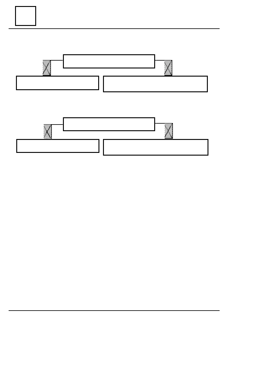
REAR RIGHT FOGG LAMP NOR WORKING

Check if the bulb is not burnt.

The bulb is burnt; replace it

between.

The bulb is not burnt; the supply wire lamps

is broken or not connected.

REAR RIGHT FOGG LAMP WORKING;

THE WARNING IS NOT WORKING

Check if the warning bulb is not burnt.

The bulb is burnt; replace it.

The bulb is not burnt. The bulb supply or

the instrument panel mass are broken.

80 - 2

DIAGNOSTIC

82

HORN - ENGINE IMMOBILISER

 PRESENTATION

 This anti starting system ( type 0802) is composed of the following components

elements:

- UCE anti starting (1) attached by means of  three screws on  the side wall of  the left  side

dashboard;

- anti starting electronic keys (2) are attached to the vehicle keys;
- anti starting receiver (3) is fixed  by clips on the dashboard, in the left side of the central

aerator.

The anti starting electronic control unit (UCE ) is connected at the front wiring of the vehicle

by means of a 10 ways connector which is attached by means of a gear behind the left side
dashboard.
   The anti starting receiver  is connected to anti starting UCE by means of a 4 ways connector
and has a double purpose:

- transferring the information received from the electronic key to the UCE anti starting;
- showing the active or not active state of the the anti starting, confirmed by LED indicator

lighting respectively lighting off, placed on the receiver.

82 - 1

1

2

3

PRESENTATION

HORN - ENGINE IMMOBILISER

82

CIRCUIT DIAGRAM

   On the circuit diagram of the system type 0802, the followings component elements may be

identified:

1. UCE anti starting
2. Anti starting receiver (2 a = electronic key contact, 2 b = anti starting LED indicator)
3. Inside fuse box
4. Left connection plate ( + I.C. )
5. Anti theft device (starting - ignition contact)
6. Rear/front wiring connection
7. Electric fuel pump
8. Left side dashboard ground.
9. Front/fuel injection wiring connection

82 - 2

PRESENTATION

82

HORN - ENGINE IMMOBILISER

OPERATING CONDITIONS

 The anti starting has the purpose to block the supply of the electric fuel pump and the ignition

and injection system.

The anti starting system is automatically armed after 30 seconds from the ignition

contact off.( bringing  the  key  on  “S” position or taking out the key from the anti theft device); the
LED indicator will light, showing in  this way that anti starting system has been activated.

To turn off the anti starting, consequently to start the engine, it is necessary the bringing of the

electronic key end in the contact with the anti starting receiver. In this moment the LED indicator
placed on the dashboard will light off confirming in this way that the anti starting system has been
turned off and the vehicle starting is now authorised.

If the LED indicator does not light off, then the electronic key does not belong to the vehicle or

there is a defect in the anti starting system.

ATTENTION !

The system activation may be also obtained without waiting the 30 seconds timing

after engine stopping. To do that it is necessary the bringing of the electronic key end
in contact with the anti starting receiver; in this moment the LED indicator will light
on, and the anti starting will become active.

UCE anti starting is provided with a safety circuit which restrains the anti starting

activation when the engine is not started.

The electronic keys are not provided with batteries for operation .These keys are

coded and consequently specific for only one vehicle, their using for another vehicle
will not enable that engine starting.

82 - 3

PRESENTATION


Content   ..  129  130  131  132   ..