Nissan Versa Sedan. Instruction - part 391


  Index      Nissan     Nissan Versa Sedan (2014 year) - Service and Repair Instruction


Search            copyright infringement  


Content   ..  389  390  391  392   ..


Nissan Versa Sedan. Instruction - part 391


CYLINDER BLOCK

EM-99

< UNIT DISASSEMBLY AND ASSEMBLY >

[HR16DE]

C

D

E

F

G

H

I

J

K

L

M

A

EM

N

P

O

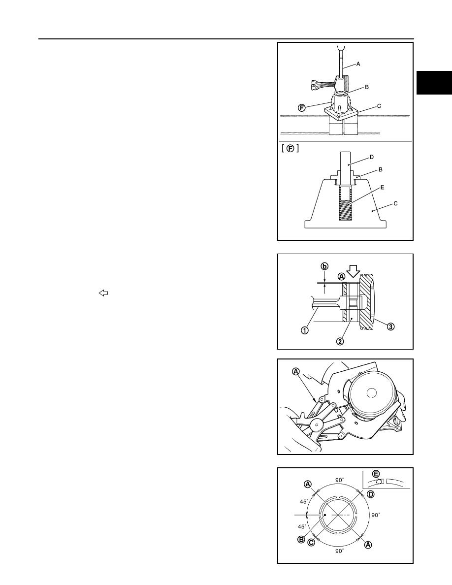
b. Press-fit the piston pin using the Tools (A, B, C, D, E).

CAUTION:

Press-fit the piston so as not to damage it.

NOTE:

The joint between the connecting rod and the piston pin is a

press fit.

• Press-fit the piston pin (2) from piston surface (A) to the depth

of 2.35 mm (0.092 in) (b).

• After finishing work, check that the piston (3) moves freely.

9. Using suitable tool (A), install piston rings. 

CAUTION:

• Be careful not to damage piston.

• Be careful not to damage piston rings by expanding them

excessively.

• Position each ring with the gap as shown referring to the pis-

ton front mark (B).

• Install second ring with the stamped mark (E) facing upward.

Tool number (A) : KV10109730
                     (B)

: KV10110310

                     (C)

: ST13030020

                     (D)

: KV10114120

                     (E)

: ST13030030

                     (F)

: Detail

PBIC5271J

(1) : Connecting rod

: Press-fit direction

JPBIA2058ZZ

PBIC3233J

(A)

: Oil ring upper or lower rail gap (either of them)

(C)

: Second ring and oil ring spacer gap

(D)

: Top ring gap

PBIC3752E

EM-100

< UNIT DISASSEMBLY AND ASSEMBLY >

[HR16DE]

CYLINDER BLOCK

10. Install connecting rod bearings to connecting rod and connecting rod cap.

• When installing connecting rod bearings, apply new engine oil to the bearing surface (inside). Do not

apply engine oil to the back surface, but thoroughly clean it. 

• Install the bearing in the center position.

NOTE:

There is no stopper tab.

• Check that the oil holes on connecting rod and connecting rod bearing are aligned.

• Install the connecting rod in the dimension (A) as shown.

NOTE:

Install the connecting rod bearing in the center position with

the dimension as shown. For service operation, the center

position can be checked visually.

11. Install piston and connecting rod assembly to crankshaft. 

• Position crankshaft pin corresponding to connecting rod to be installed onto the bottom dead center. 

• Apply new engine oil sufficiently to the cylinder bore, piston and crankshaft pin. 

• Match the cylinder position with the cylinder number on connecting rod to install. 

• Using Tool (A) or suitable tool, install piston with the front mark

on the piston head facing the front of the engine. 

CAUTION:

• Be careful not to damage mating surface with connect-

ing rod cap.

• Be careful not to damage the cylinder wall or crankshaft

pin. 

12. Install connecting rod cap. 

• Match the stamped cylinder number marks (C) on connecting

rod with those on connecting rod cap to install.   

13. Inspect outer diameter of connecting rod bolts. Refer to 

EM-103, "Inspection"

.

14. Tighten connecting rod bolt:
a. Apply new engine oil to the threads and seats of connecting rod bolts. 

Stamped mark:

Top ring

: 1R

Second ring

: 2R

(1)

: Connecting rod

(2)

: Connecting rod bearing (upper)

(3)

: Connecting rod bearing (lower)

(4)

: Connecting rod cap

(A)

: 1.7 - 2.1 mm (0.067 - 0.083 in)

: Engine front

PBIC4169E

Tool number

: EM03470000 

PBIC3765E

(A) : Front mark
(B) : Oil hole
(D) : Connecting rod big end grade

PBIC3766E

CYLINDER BLOCK

EM-101

< UNIT DISASSEMBLY AND ASSEMBLY >

[HR16DE]

C

D

E

F

G

H

I

J

K

L

M

A

EM

N

P

O

b. Tighten connecting rod bolts in several steps.

c. Completely loosen connecting rod bolts.

d. Tighten connecting rod bolts in several steps.

e. Then turn all connecting rod bolts 60 degrees clockwise (angle tightening).

CAUTION:

Check and confirm the tightening angle by using the Tool (A) or protractor. Avoid judgement by

visual inspection without the Tool.

• After tightening connecting rod bolt, check that crankshaft rotates smoothly. 

• Check the connecting rod side clearance. Refer to 

EM-103, "Inspection"

.

15. Install oil pan (upper). Refer to 

EM-89, "Exploded View"

.

NOTE:

Install the rear oil seal after installing the oil pan (upper).

16. Install rear oil seal. Refer to 

EM-71, "REAR OIL SEAL : Removal and Installation"

.

17. Install flywheel (M/T models) or drive plate (A/T and CVT models).

M/T models

• Secure crankshaft with a stopper plate (A) and tighten bolts

crosswise over several times.

A/T and CVT models

Connecting rod bolts

: 27.4 N·m (2.8 kg-m, 20 ft-lb)

Connecting rod bolts

: 0 N·m (0 kg-m, 0 ft-lb)

Connecting rod bolts

: 19.6 N·m (2.0 kg-m, 14 ft-lb)

Tool number

: KV10112100 (BT-8653-A)

PBIC3753E

(1) :Flywheel

Tool number

: KV11105210 (J-44716)

MBIB1382E

EM-102

< UNIT DISASSEMBLY AND ASSEMBLY >

[HR16DE]

CYLINDER BLOCK

• Secure crankshaft with a stopper plate (A) and tighten bolts

crosswise over several times.

CAUTION:

Be careful not to damage or scratch and contact surface for clutch disc of flywheel.

18. Install knock sensor (1).

• Install connectors so that they are positioned toward the rear

of the engine.

CAUTION:

• Do not tighten bolt while holding the connector.   

• If any impact by dropping is applied to knock sensor,

replace it with a new one.

NOTE:

• Check that there is no foreign material on the cylinder block

mating surface and the back surface of knock sensor. 

• Check that knock sensor does not interfere with other parts.

19. Install crankshaft position sensor (POS) (2) using a new O-ring

(1) and then install the crankshaft position sensor cover (3) on

the cylinder block (4).

• Tighten bolts with sensor inserted completely.

CAUTION:

• Avoid impacts such as a dropping.

• Do not disassemble.

• Keep sensor away from metal particles.

• Do not place the sensor in a location where it is exposed

to magnetism.

• Do not reuse O-ring.

20. For the oil level gauge guide (1), secure in position (B) shown to

the water inlet clip (A) after inserting to the cylinder block side.

21. Assembly of the remaining components is in the reverse order of disassembly. 

(1) :Drive plate

Tool number

: KV11105210 (J-44716)

PBIC3226J

: Engine front

: Engine front

PBIC3754E

JPBIA4202ZZ

PBIC3755E


Content   ..  389  390  391  392   ..