Nissan Versa Sedan. Instruction - part 390


  Index      Nissan     Nissan Versa Sedan (2014 year) - Service and Repair Instruction


Search            copyright infringement  


Content   ..  388  389  390  391   ..


Nissan Versa Sedan. Instruction - part 390


CYLINDER BLOCK

EM-95

< UNIT DISASSEMBLY AND ASSEMBLY >

[HR16DE]

C

D

E

F

G

H

I

J

K

L

M

A

EM

N

P

O

Disassembly and Assembly

INFOID:0000000009266677

DISASSEMBLY

NOTE:

The following procedures explain how to disassemble the engine with the engine stand fastened to the bell

housing. Some steps may be different if using a different type of engine stand.
1. Remove cylinder head. Refer to 

EM-73, "Exploded View"

.

2. Remove knock sensor.

CAUTION:

Carefully handle knock sensor avoiding shocks.

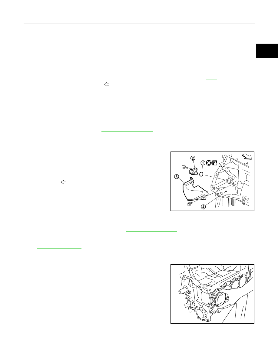
3. Remove the crankshaft position sensor cover (3), and then

crankshaft position sensor (POS) (2).

CAUTION:

• Avoid impacts such as a dropping.

• Do not disassemble.

• Keep sensor away from metal particles.

• Do not place the sensor in a location where it is exposed

to magnetism.

• Do not reuse O-ring.

4. Remove oil pan (upper and lower). Refer to 

EM-89, "Exploded View"

.

5. Remove piston and connecting rod assembly:

• Before removing piston and connecting rod assembly, check the connecting rod side clearance. Refer to

EM-103, "Inspection"

.

a. Position crankshaft pin corresponding to connecting rod to be removed onto the bottom dead center. 
b. Remove connecting rod cap. 
c. Using a hammer handle or similar tool, push piston and connect-

ing rod assembly out through the cylinder head side. 

CAUTION:

• Be careful not to damage mating surface with connecting

rod cap.

• Be careful not to damage the cylinder wall or crankshaft

pin. 

6. Remove connecting rod bearings. 

CAUTION:

Identify original positions for installation, and store the bearings without mixing them up.

10. Oil temperature sensor

11. Oil pressure sensor

12. Oil jet

13. Top ring

14. Second ring

15. Oil ring

16. Piston

17. Piston pin

18. Connecting rod

19. Connecting rod bearing (upper)

20. Main bearing (upper)

21. Thrust bearing

22. Crankshaft key

23. Connecting rod bolt

24. Connecting rod cap

25. Connecting rod bearing (lower)

26. Main bearing (lower)

27. Crankshaft

28. Pilot converter (A/T and CVT models)

29. Signal plate

30. Rear oil seal

31. Drive plate (A/T and CVT models)

32. Reinforce plate (A/T and CVT models) 33. Flywheel (M/T models)

34. Main bearing cap

35. Main bearing cap bolt

A.

 Refer to 

EM-95

B.

Chamfered

: Crankshaft side

(1) O-ring
(4) Cylinder block

: Engine front

JPBIA4202ZZ

KBIA3365J

EM-96

< UNIT DISASSEMBLY AND ASSEMBLY >

[HR16DE]

CYLINDER BLOCK

7. Remove piston rings from piston. 

• Before removing piston rings, check the piston ring side clearance. Refer to 

EM-103, "Inspection"

.

• Use a suitable tool) (A) as shown.

CAUTION:

• When removing piston rings, be careful not to damage

the piston.

• Be careful not to damage piston rings by expanding

them excessively.

8. Remove piston from connecting rod.

• Use a Tools (A, B, C) and a press to remove the piston pin.

CAUTION:

• Do not damage the piston and connecting rod.

• Do not reuse piston and piston pin after removing piston

pin from connecting rod. 

• The connecting rod is reusable.

NOTE:

The joint between the connecting rod and the piston pin is a press fit.

9. Remove the main bearing cap.

• Measure crankshaft end play before loosening main bearing cap bolts. Refer to 

EM-103, "Inspection"

.

a. Loosen and remove bolts in several steps in reverse of the

numerical order as shown.

NOTE:

When removing or installing signal plate, use socket (size T40).

b. Remove the main bearing cap from the cylinder block while tapping lightly with a plastic hammer.

10. Remove crankshaft (2).

CAUTION:

• Be careful not damage or deform signal plate (1) mounted

on crankshaft.

• When setting crankshaft on a flat floor surface, use a

block of wood to avoid interference between signal plate

and the floor surface.

• Do not remove signal plate unless it is necessary to do

so.

NOTE:

When removing or installing signal plate, use socket (size T40).

11. Pull rear oil seal out from rear end of crankshaft.
12. Remove main bearing (upper and lower) and thrust bearings from cylinder block and main bearing caps.

CAUTION:

PBIC3233J

Tool Number (A) : KV10109730
                     (B)

: KV10110310

                     (C)

: ST13030020

PBIC5270J

: Engine front

JPBIA4203ZZ

JPBIA4531ZZ

CYLINDER BLOCK

EM-97

< UNIT DISASSEMBLY AND ASSEMBLY >

[HR16DE]

C

D

E

F

G

H

I

J

K

L

M

A

EM

N

P

O

Identify original installation positions, and store the bearings without mixing them up.

13. Remove oil jets.

CAUTION:

Insert the dowel pin of oil jet into the cylinder block dowel pin hole to loosen the bolt.

ASSEMBLY

CAUTION:

Do not reuse O-rings.
1. Fully air-blow engine coolant and engine oil passages in cylinder block, cylinder bore and crankcase to

remove any foreign material.

WARNING:

Use goggles to protect your eyes.

2. Install oil jets.
3. Install main bearings and thrust bearings:
a. Remove dust, dirt, and engine oil on the bearing mating surfaces of cylinder block.
b. Install thrust bearings to the both sides of the No. 3 journal hous-

ing (B) on cylinder block.

• Install thrust bearings with the oil groove (A) facing crankshaft

arm (outside). 

c. Install the main bearings paying attention to the direction.

• Before installing main bearings, apply new engine oil to the bearing surface (inside). Do not apply

engine oil to the back surface, but thoroughly clean it.

• When installing, align main bearing to the center position of cylinder block and main bearing cap.

• Ensure the oil holes on cylinder block and oil holes (A) on the

main bearings (1) are aligned.

NOTE:

For assembly, the center position can be visually identified.

• To install the main bearing, obtain a proper fit. Do not allow the

main bearing to lie off the cylinder block chamfer.

• To install the main bearing, obtain a proper fit. Do not allow the

main bearing to lie off bearing cap chamfer.

4. Install signal plate to crankshaft if removed.
a. Set the signal plate (1) with the flange facing toward the counter-

weight side (engine front side) to the crankshaft rear surface.

b. After positioning crankshaft and signal plate with positioning

dowel pin, tighten bolt.

NOTE:

Dowel pin of crankshaft and signal plate is provided as a set for

each.

c. Remove dowel pin.

CAUTION:

Be sure to remove dowel pin.

5. Install crankshaft to cylinder block.

: Engine front

PBIC3258J

PBIC3746E

(A) : Dowel pin hole

JPBIA4231ZZ

EM-98

< UNIT DISASSEMBLY AND ASSEMBLY >

[HR16DE]

CYLINDER BLOCK

• While turning crankshaft by hand, check that it turns smoothly. 

CAUTION:

Do not install rear oil seal at this time.

6. Install main bearing caps.

• Install the main bearing cap while referring to the front mark

(B) and the journal number stamp (A).

NOTE:

Main bearing cap cannot be replaced as a single part,

because it is machined together with cylinder block.

7. Tighten main bearing cap bolts in numerical order as shown with

the following steps:

a. Apply new engine oil to threads and seat surfaces of the bolts.
b. Tighten main bearing cap bolts in numerical order.

c.

Turn main bearing cap bolts 60 degrees clockwise (angle tight-

ening) in numerical order as shown.

CAUTION:

Check and confirm the tightening angle by using the Tool

(A) or protractor. Avoid judgment by visual inspection with-

out the Tool. 

• After installing the main bearing cap bolts, check that crankshaft can be rotated smoothly by hand.

• Check crankshaft end play. Refer to 

EM-103, "Inspection"

.

8. Install piston to connecting rod with the following procedure: 
a. Set so that the front mark (A) on the piston head and the cylin-

der number (C) are in the position as shown.

NOTE:

The symbols without notes are for manufacturing.

: Engine front

JPBIA4204ZZ

: Engine front

Main bearing cap bolts

: 32.4 N·m (3.3 kg-m, 24 ft-lb)

JPBIA4203ZZ

Tool number

: KV10112100 (BT-8653-A)

PBIC3750E

(B) : Oil hole
(D) : Connecting rod big end grade

PBIC3766E


Content   ..  388  389  390  391   ..