Nissan Versa Sedan. Instruction - part 389


  Index      Nissan     Nissan Versa Sedan (2014 year) - Service and Repair Instruction


Search            copyright infringement  


Content   ..  387  388  389  390   ..


Nissan Versa Sedan. Instruction - part 389


OIL PAN (UPPER) AND OIL STRAINER

EM-91

< UNIT DISASSEMBLY AND ASSEMBLY >

[HR16DE]

C

D

E

F

G

H

I

J

K

L

M

A

EM

N

P

O

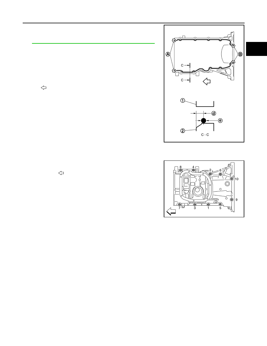
c. Apply a continuous bead of liquid gasket with the Tool or suitable

tool to areas as shown.

Use Genuine Silicone RTV Sealant or equivalent. Refer to

GI-21, "Recommended Chemical Products and Sealants"

.

CAUTION:

Attaching should be done within 5 minutes after coating.

d. Tighten bolts in the numerical order as shown.

CAUTION:

Install avoiding misalignment of both oil pan gasket and O-

ring.

• The bolts are different according to the installation position.

Refer to the numbers as shown.

2. Install rear oil seal:

CAUTION:

• The installation of rear oil seal should be completed within 5 minutes after installing oil pan

(upper).

• Do not touch oil seal lip.

a. Wipe off any liquid gasket protruding to the rear oil seal mounting part of oil pan (upper) and cylinder block

using a suitable tool.

b. Apply the liquid gasket lightly to entire outside area of new rear oil seal. 

Use Genuine Liquid Gasket or equivalent.

(1) : Cylinder block
(2) : Oil pan (upper)
(A) : 2 mm (0.07 in) protruded to outside
(B) : 2 mm (0.07 in) protruded to rear oil seal mounting side
(d) : 5.5 - 7.5 mm (0.217 - 0.295 in)
(e) : 4.0 - 5.0 mm (0.157 - 0.197 in) diameter

: Engine front side

JSBIA1301ZZ

: Engine front

M8

×180 mm (7.09 in)

: No. 9, 10

M8

×25 mm (0.98 in)

: No. 4, 7, 8 

M8

×90 mm (3.54 in)

: No. 1, 2, 3, 5, 6 

JPBIA4199ZZ

EM-92

< UNIT DISASSEMBLY AND ASSEMBLY >

[HR16DE]

OIL PAN (UPPER) AND OIL STRAINER

c.

Press-fit the rear oil seal using a drift with outer diameter 113

mm (4.45 in) and inner diameter 90 mm (3.54 in) (commercial

service tool) (A).

• Press-fit to the dimensions specified as shown.

CAUTION:

• Do not touch the grease applied to the oil seal lip.

• Be careful not to damage the rear oil seal mounting part

of oil pan (upper) and cylinder block or the crankshaft.

• Press-fit straight and check that oil seal does not curl or

tilt.

d. After press-fitting the rear oil seal, completely wipe off any liquid

gasket protruding to rear end surface side.

3. Installation of the remaining components is in the reverse order of removal. 
4. Add the specified oil after waiting for at least 30 minutes. Refer to 

MA-12, "Fluids and Lubricants"

.

CAUTION:

• The components must be installed within 5 minutes of the liquid gasket application. 

• Allow 30 minutes for the liquid gasket to set before adding oil to the engine.

INSPECTION AFTER INSTALLATION

• Before starting engine, check oil/fluid levels, including engine coolant and engine oil. If less than required

quantity, fill to the specified level. Refer to 

MA-12, "Fluids and Lubricants"

.

• Use procedure below to check for fuel leakage.

• Turn ignition switch ON (with engine stopped). With fuel pressure applied to fuel piping, check for fuel leak-

age at connection points.

• Start engine. With engine speed increased, check again for fuel leakage at connection points.

• Run engine to check for unusual noise and vibration.

NOTE:

If hydraulic pressure inside timing chain tensioner drops after removal and installation, slack in the guide

may generate a pounding noise during and just after engine start. However, this is normal. Noise will stop

after hydraulic pressure rises.

• Warm up engine thoroughly to make sure there is no leakage of fuel, exhaust gas, or any oils/fluids including

engine oil and engine coolant.

• Bleed air from passages in lines and hoses, such as in cooling system.

• After cooling down engine, again check oil/fluid levels including engine oil and engine coolant. Refill to spec-

ified level, if necessary.

• Summary of the inspection items:

PBIC3660E

(1) : Rear oil seal
(A) : Rear end surface of cylinder block

PBIC3149J

Item

Before starting engine

Engine running

After engine stopped

Engine coolant

Level

Leakage

Level

Engine oil

Level

Leakage

Level

Transmission/
transaxle fluid 

A/T and CVT Models

Leakage

Level/Leakage

Leakage

M/T Models

Level/Leakage

Leakage

Level/Leakage

Other oils and fluids*

Level

Leakage

Level

OIL PAN (UPPER) AND OIL STRAINER

EM-93

< UNIT DISASSEMBLY AND ASSEMBLY >

[HR16DE]

C

D

E

F

G

H

I

J

K

L

M

A

EM

N

P

O

*Power steering fluid, brake fluid, etc.

Fuel

Leakage

Leakage

Leakage

Exhaust gas

Leakage

Item

Before starting engine

Engine running

After engine stopped

EM-94

< UNIT DISASSEMBLY AND ASSEMBLY >

[HR16DE]

CYLINDER BLOCK

CYLINDER BLOCK

Exploded View

INFOID:0000000009266676

1.

Crankshaft position sensor cover

2.

Crankshaft position sensor (POS)

3.

O-ring

4.

Drain plug

5.

Cylinder block

6.

Oil level gauge

7.

Oil level gauge guide

8.

O-ring

9.

Knock sensor

AWBIA1479ZZ


Content   ..  387  388  389  390   ..