Nissan Versa Sedan. Instruction - part 383


  Index      Nissan     Nissan Versa Sedan (2014 year) - Service and Repair Instruction


Search            copyright infringement  


Content   ..  381  382  383  384   ..


Nissan Versa Sedan. Instruction - part 383


CAMSHAFT

EM-67

< REMOVAL AND INSTALLATION >

[HR16DE]

C

D

E

F

G

H

I

J

K

L

M

A

EM

N

P

O

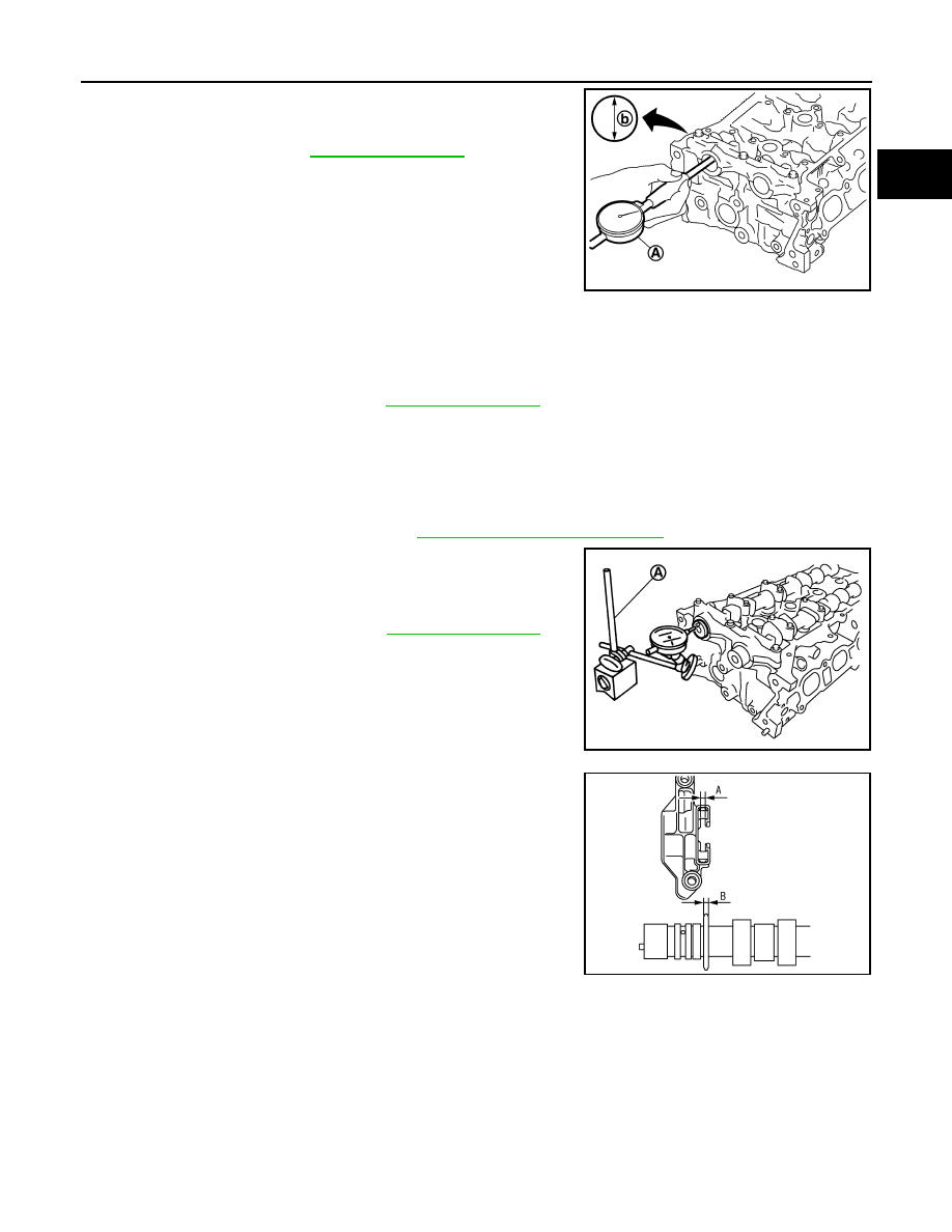
• Measure inner diameter (b) of camshaft bracket with a bore gauge

(A).

CAMSHAFT JOURNAL OIL CLEARANCE

• (Oil clearance) = (Camshaft bracket inner diameter) – (Camshaft journal diameter)

• If it exceeds the limit, replace either or both camshaft and cylinder head.

NOTE:

Camshaft brackets cannot be replaced as single parts, because they are machined together with cylinder

head. Replace whole cylinder head assembly.

Camshaft End Play

1. Install camshaft in cylinder head. Refer to 

EM-56, "Removal and Installation"

 for tightening procedure.

2. Install a dial indicator (A) in thrust direction on front end of cam-

shaft. Measure the camshaft end play on the dial indicator when

camshaft is moved forward/backward (in direction to axis).

• Measure the following parts if out of the standard.

- Dimension “A” for cylinder head No. 1 journal bearing

- Dimension “B” for camshaft thrust

• Refer to the standards above, and then replace camshaft and/

or cylinder head.

Camshaft Sprocket Runout

1. Put V-block on precise flat table, and support No. 2 and 5 journals of camshaft.

CAUTION:

Do not support No. 1 journal (on the side of camshaft sprocket) because it has a different diameter

from the other four locations.

Standard

: Refer to 

EM-118, "Camshaft"

.

JPBIA4192ZZ

Standard and Limit

: Refer to 

EM-118, "Camshaft"

.

Standard and Limit

: Refer to 

EM-118, "Camshaft"

.

PBIC3694E

Standard

: 4.000 - 4.030 mm (0.1574 - 0.1586 in)

Standard

: 3.877 - 3.925 mm (0.1526 - 0.1545 in)

KBIA3345J

EM-68

< REMOVAL AND INSTALLATION >

[HR16DE]

CAMSHAFT

2. Measure the camshaft sprocket runout with a dial indicator (A).

(Total indicator reading)

• If it exceeds the limit, replace camshaft sprocket.

Valve Lifter 

Check if surface of valve lifter has any wear or cracks.

• If anything above is found, replace valve lifter. Refer to 

EM-118,

"Camshaft"

.

Valve Lifter Clearance

VALVE LIFTER OUTER DIAMETER

• Measure the outer diameter of valve lifter with a micrometer (A).

VALVE LIFTER HOLE DIAMETER

Measure the diameter of valve lifter hole of cylinder head with an

inside micrometer (A).

VALVE LIFTER CLEARANCE

• (Valve lifter clearance) = (Valve lifter hole diameter) – (Valve lifter outer diameter)

• If out of the standard, referring to the each standard of valve lifter outer diameter and valve lifter hole diame-

ter, replace either or both valve lifter and cylinder head.

INSPECTION AFTER INSTALLATION

Limit : 0.15 mm (0.0059 in)

JPBIA4193ZZ

KBIA0182E

Standard

: Refer to 

EM-118, "Camshaft"

.

PBIC3185J

Standard

: Refer to 

EM-118, "Camshaft"

.

PBIC3184J

Standard

: Refer to 

EM-118, "Camshaft"

.

CAMSHAFT

EM-69

< REMOVAL AND INSTALLATION >

[HR16DE]

C

D

E

F

G

H

I

J

K

L

M

A

EM

N

P

O

Inspection of Camshaft Sprocket Oil Groove

CAUTION:

• Perform this inspection only when DTC P0011 or P0014 is detected in self-diagnostic results of CON-

SULT and it is directed according to inspection procedure of EC section. Refer to 

EC-161, "Diagnosis

Procedure"

 (P0011) or 

EC-165, "Diagnosis Procedure"

 (P0014).

• Check when engine is cold so as to prevent burns from the splashing engine oil.

NOTE:

This section provides the inspection method of oil passage of cam sprocket on the intake side. For oil passage

on the exhaust side, the inspection procedure must be changed as instructed below:

1. Check engine oil level. Refer to 

LU-8, "Inspection"

.

2. Perform the following procedure so as to prevent the engine from being unintentionally started while

checking.

a. Release the fuel pressure. Refer to 

EC-133, "Work Procedure"

.

b. Remove intake manifold. Refer to 

EM-27, "Exploded View"

.

c. Disconnect ignition coil and injector harness connectors. Refer to 

EM-44, "Exploded View"

.

3. Remove intake valve timing control solenoid valve. Refer to 

EM-56, "Exploded View"

.

4. Crank engine, and then check that engine oil comes out from

intake valve timing control solenoid valve hole (A). End crank

after checking.

WARNING:

Be careful not to touch rotating parts (drive belts, idler pul-

ley, and crankshaft pulley, etc.).

CAUTION:

• Prevent splashing by using a shop cloth to prevent injury

from splashing engine oil and so as to prevent engine oil contamination.

• Use a shop cloth to prevent engine oil from being splashed to engine and vehicle. Especially be

careful not to spill engine oil to rubber parts of drive belts, engine mounting insulator, etc. Wipe

engine oil off immediately if it is splashed.

5. Perform the following inspection if engine oil does not come out from intake valve timing control solenoid

valve oil hole of the cylinder head.

• Remove oil filter, and then clean it. Refer to 

LU-11, "Removal and Installation"

.

• Clean oil groove between oil strainer and intake valve timing control solenoid valve. Refer to 

LU-6,

"Engine Lubrication System"

.

6. Remove components between intake valve timing control solenoid valve and camshaft sprocket (INT),

and then check each oil groove for clogging.

• Clean oil groove if necessary. Refer to 

LU-6, "Engine Lubrication System"

.

7. After inspection, installation of components is in the reverse order of removal

· Step 3

: Remove exhaust valve timing control solenoid valve. Refer to 

EM-56, "Exploded View"

.

· Step 4

: Crank engine, and then check that engine oil comes out from exhaust valve timing control solenoid 
valve hole (A). End crank after checking.

·Step 5

Perform the following inspection if engine oil does not come out from exhaust valve timing control 
solenoid valve oil hole of the cylinder head.
• Remove oil filter, and then clean it. Refer to 

EM-56, "Exploded View"

.

• Clean oil groove between oil strainer and exhaust valve timing control solenoid valve. Refer to 

EM-56, "Exploded View"

.

·Step 6

: Remove components between exhaust valve timing control solenoid valve and camshaft sprocket 
(EXH), and then check each oil groove for clogging.

(1) : Plug

:Engine front

JPBIA4194ZZ

EM-70

< REMOVAL AND INSTALLATION >

[HR16DE]

OIL SEAL

OIL SEAL

VALVE OIL SEAL
VALVE OIL SEAL : Removal and Installation

INFOID:0000000009266662

REMOVAL

1. Remove camshafts. Refer to  

EM-56, "Removal and Installation"

.

2. Remove valve lifters. Refer to  

EM-56, "Removal and Installation"

.

3. Rotate crankshaft, and set piston with valve oil seal to be removed to TDC. This will prevent the valve

from dropping into cylinder.

CAUTION:

When rotating crankshaft, be careful to avoid scarring front cover with timing chain.

4. Remove valve collet. 

• Compress valve spring with Tool (A). Remove valve collet with

a magnet hand (B).

CAUTION:

Be careful not to damage valve lifter holes.

5. Remove valve spring retainer, valve spring and valve spring seat. Refer to 

EM-75, "Disassembly and

Assembly"

.

6. Remove valve oil seal with Tool (A).

INSTALLATION

1. Apply new engine oil to valve oil seal joint surface and seal lip.
2. Press in valve oil seal to the height “H” shown with Tool (A).

3. Installation of the remaining components is in the reverse order of removal. 

FRONT OIL SEAL

Tool number

: KV10116200 (J-26336-B)
: KV10115900 (J-26336-20)
: KV10109220 (   —   )

PBIC3727E

Tool number

: KV10107902 (J-38959)

PBIC3728E

Height “H”

: 13.2 - 13.8 mm (0.520 - 0.543 in)

Tool number

: KV10115600 (J-38958)

PBIC3211J


Content   ..  381  382  383  384   ..