Nissan Versa Sedan. Instruction - part 382


  Index      Nissan     Nissan Versa Sedan (2014 year) - Service and Repair Instruction


Search            copyright infringement  


Content   ..  380  381  382  383   ..


Nissan Versa Sedan. Instruction - part 382


CAMSHAFT

EM-63

< REMOVAL AND INSTALLATION >

[HR16DE]

C

D

E

F

G

H

I

J

K

L

M

A

EM

N

P

O

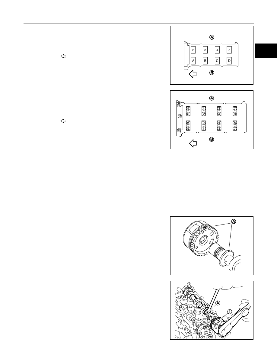
7. Install camshaft brackets (No. 2 to 5) aligning the identification

marks on upper surface as shown.

• Install so that identification mark can be correctly read when

viewed from the INT side.

8. Tighten bolts of camshaft brackets in the following steps, in

numerical order as shown.

a. Tighten No. 9 to 11 in numerical order.

b. Tighten No. 1 to 8 in numerical order.

c. Tighten all bolts in numerical order.

d. Tighten all bolts in numerical order.

9. Install the camshaft sprocket (INT and EXH) to the camshaft (INT and EXH): 
a. Refer to the matching mark (A) added in step 4. Securely align

the knock pin and the pin hole, and then install them.

NOTE:

The intake side is shown as an example.

10. Tighten the camshaft sprocket bolt (INT and EXH).

CAUTION:

Hold the camshaft hexagonal part (A), using a suitable tool

to secure the camshaft.

(A) : EXH side
(B) : INT side

: Engine front

PBIC3703E

(A) : EXH side
(B) : INT side

: Engine front

Camshaft bracket bolts

: 1.96 N·m (2.0 kg-m, 14 in-lb)

Camshaft bracket bolts

: 1.96 N·m (2.0 kg-m, 14 in-lb)

Camshaft bracket bolts

: 5.88 N·m (0.60 kg-m, 52 in-lb)

Camshaft bracket bolts

: 10.4 N·m (1.1 kg-m, 8 ft-lb)

PBIC3686E

PBIC3700E

(1) : Camshaft sprocket (EXH)

JPBIA4158ZZ

EM-64

< REMOVAL AND INSTALLATION >

[HR16DE]

CAMSHAFT

11. Install the camshaft (INT and EXH) to the camshaft sprocket

(INT and EXH) (2 and 3) while aligning the matching mark

(marked when timing chain is removed) (A) and the pink link (B)

of camshaft sprocket (INT and EXH).

• If the positions of knock pin and pin groove are not aligned,

move the camshaft (EXH) slightly to correct these positions.

12. Pull out the stopper pin (A), and then apply the tension to the

timing chain by rotating the crankshaft pulley clockwise slightly.

13. Pull out the stopper pin of chain tensioner.
14. Install front cover.
15. Return the camshaft sprocket (INT) in the most retarded position:
a. Remove the stopper pin (A) from the camshaft sprocket (INT).

b. Turn the crankshaft pulley (1) slowly clockwise (A) and return

the camshaft sprocket (INT) to the most retarded angle position.

(1) : Timing chain 
(C) : Matching mark (peripheral groove)

JPBIA4159ZZ

(1) : Plunger
(2) : Chain tensioner
(B) : Lever
(C) : Lever hole
(D) : Front cover has been removed for clarity.

PBIC3772E

(B) : Tape

PBIC3685E

PBIC3704E

CAMSHAFT

EM-65

< REMOVAL AND INSTALLATION >

[HR16DE]

C

D

E

F

G

H

I

J

K

L

M

A

EM

N

P

O

• When first turning the crankshaft, the camshaft sprocket (INT)

will turn. Once it is turned more, and the vane (camshaft) also

turns, then it has reached the most retarded angle position.

• The most retarded angle position can be checked by seeing if

the stopper pin groove (A) is shifted clockwise.

• After spinning the crankshaft slightly in the counterclockwise

direction, you can check the lock pin has joined by seeing if

the vane (camshaft) and the sprocket move together.

16. Install the camshaft position sensor (PHASE) to the rear end of cylinder head.

• Tighten bolts with it completely inserted.

17. Check and adjust valve clearance. Refer to 

EM-10, "Inspection and Adjustment"

.

18. Installation of the remaining components is in the reverse order of removal.

INSPECTION AFTER INSTALLATION

• Before starting engine, check oil/fluid levels, including engine coolant and engine oil. If less than required

quantity, fill to the specified level. Refer to 

MA-12, "Fluids and Lubricants"

.

• Use procedure below to check for fuel leakage.

• Turn ignition switch ON (with engine stopped). With fuel pressure applied to fuel piping, check for fuel leak-

age at connection points.

• Start engine. With engine speed increased, check again for fuel leakage at connection points.

• Run engine to check for unusual noise and vibration.

NOTE:

If hydraulic pressure inside timing chain tensioner drops after removal and installation, slack in the guide

may generate a pounding noise during and just after engine start. However, this is normal. Noise will stop

after hydraulic pressure rises.

• Warm up engine thoroughly to make sure there is no leakage of fuel, exhaust gas, or any oils/fluids including

engine oil and engine coolant.

• Bleed air from passages in lines and hoses, such as in cooling system.

• After cooling down engine, again check oil/fluid levels including engine oil and engine coolant. Refill to spec-

ified level, if necessary.

• Summary of the inspection items:

*Power steering fluid, brake fluid, etc.

Inspection

INFOID:0000000009266661

INSPECTION AFTER REMOVAL

Oil Filter

(B) : Stopper pin hole
(C) : Most advanced angle
(D) : Lock pin engaged 

PBIC3705E

Item

Before starting engine

Engine running

After engine stopped

Engine coolant

Level

Leakage

Level

Engine oil

Level

Leakage

Level

Transmission/
transaxle fluid 

A/T and CVT Models

Leakage

Level/Leakage

Leakage

M/T Models

Level/Leakage

Leakage

Level/Leakage

Other oils and fluids*

Level

Leakage

Level

Fuel

Leakage

Leakage

Leakage

Exhaust gas

Leakage

EM-66

< REMOVAL AND INSTALLATION >

[HR16DE]

CAMSHAFT

• Check that there is no foreign material on the oil filter (1) and check

it for clogging.

• Check the oil filter for damage.

• If there is some damage, replace the oil filter, the plug, and the

washer as a set.

CAUTION:

Do not reuse the washer.

Camshaft Runout

1. Put V-block on a precise flat table, and support No. 2 and 5 jour-

nals of camshaft.

CAUTION:

Do not support No. 1 journal (on the side of camshaft

sprocket) because it has a different diameter from the other

four locations.

2. Set a dial indicator vertically to No. 3 journal.
3. Turn camshaft to one direction, and measure the camshaft

runout on the dial indicator. (Total indicator reading)

4. If it exceeds the limit, replace camshaft.

Camshaft Cam Height

1. Measure the camshaft cam height with a micrometer (A).

2. If wear exceeds the limit, replace camshaft.

Camshaft Journal Oil Clearance

CAMSHAFT JOURNAL DIAMETER

Measure the outer diameter of camshaft journal with a micrometer

(A).

CAMSHAFT BRACKET INNER DIAMETER

• Tighten camshaft bracket bolts to the specified torque. Refer to "INSTALLATION" for the tightening proce-

dure.

PBIC3693E

Standard and Limit

: Refer to 

EM-118, "Camshaft"

.

PBIC2499E

Standard and Limit

Intake

: Refer to 

EM-118, "Camshaft"

.

Exhaust

Cam wear limit:

: Refer to 

EM-118, "Camshaft"

.

PBIC3178J

Standard:

: Refer to 

EM-118, "Camshaft"

.

PBIC3179J


Content   ..  380  381  382  383   ..