Nissan Versa Sedan. Instruction - part 380


  Index      Nissan     Nissan Versa Sedan (2014 year) - Service and Repair Instruction


Search            copyright infringement  


Content   ..  378  379  380  381   ..


Nissan Versa Sedan. Instruction - part 380


TIMING CHAIN

EM-55

< REMOVAL AND INSTALLATION >

[HR16DE]

C

D

E

F

G

H

I

J

K

L

M

A

EM

N

P

O

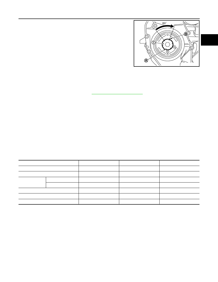
c. Put a paint mark (B) on crankshaft pulley, mating with any one of

six easy to recognize angle marks (A) on crankshaft bolt flange

(1). 

d. Turn another 60 degrees clockwise (angle tightening).

• Check the tightening angle with movement of one angle mark.

10. Check that crankshaft turns smoothly by rotating by hand clockwise.
11. Installation of the remaining components is in the reverse order of removal.

INSPECTION AFTER INSTALLATION

• Before starting engine, check oil/fluid levels, including engine coolant and engine oil. If less than required

quantity, fill to the specified level. Refer to 

MA-12, "Fluids and Lubricants"

.

• Use procedure below to check for fuel leakage.

• Turn ignition switch ON (with engine stopped). With fuel pressure applied to fuel piping, check for fuel leak-

age at connection points.

• Start engine. With engine speed increased, check again for fuel leakage at connection points.

• Run engine to check for unusual noise and vibration.

NOTE:

If hydraulic pressure inside timing chain tensioner drops after removal and installation, slack in the guide

may generate a pounding noise during and just after engine start. However, this is normal. Noise will stop

after hydraulic pressure rises.

• Warm up engine thoroughly to make sure there is no leakage of fuel, exhaust gas, or any oils/fluids including

engine oil and engine coolant.

• Bleed air from passages in lines and hoses, such as in cooling system.

• After cooling down engine, again check oil/fluid levels including engine oil and engine coolant. Refill to spec-

ified level, if necessary.

• Summary of the inspection items:

*Power steering fluid, brake fluid, etc.

PBIC3726E

Item

Before starting engine

Engine running

After engine stopped

Engine coolant

Level

Leakage

Level

Engine oil

Level

Leakage

Level

Transmission/
transaxle fluid 

A/T and CVT Models

Leakage

Level/Leakage

Leakage

M/T Models

Level/Leakage

Leakage

Level/Leakage

Other oils and fluids*

Level

Leakage

Level

Fuel

Leakage

Leakage

Leakage

Exhaust gas

Leakage

EM-56

< REMOVAL AND INSTALLATION >

[HR16DE]

CAMSHAFT

CAMSHAFT

Exploded View

INFOID:0000000009266659

Removal and Installation

INFOID:0000000009266660

CAUTION:

The rotation direction indicated in the procedure is as viewed from the engine front. 

REMOVAL

1. Hold the bottom surface of the engine with a jack to remove the right engine mount assembly and the

insulator. Refer to 

EM-82, "Exploded View"

.

2. Remove rocker cover. Refer to 

EM-44, "Exploded View"

.

3. Place cylinder No. 1 at TDC of its compression stroke:

1.

Camshaft bracket (No. 2 to 5)

2.

Camshaft bracket (No. 1)

3.

Camshaft sprocket (EXH)

4.

Exhaust valve timing control sole-
noid valve

5.

O-ring

6.

Camshaft sprocket (INT)

7.

Plug (EXH)

8.

Washer (EXH)

9.

Oil filter (for exhaust valve timing control 
solenoid valve)

10. Cylinder head

11.

Oil filter (for intake valve timing 
control solenoid valve)

12. Washer (INT)

13. Plug (INT)

14. O-ring

15. Intake valve timing control solenoid 

valve

16. Bracket

17. Valve lifter

18. Camshaft (INT)

19. Camshaft (EXH)

A.

Refer to 

EM-56

AWBIA1476ZZ

CAMSHAFT

EM-57

< REMOVAL AND INSTALLATION >

[HR16DE]

C

D

E

F

G

H

I

J

K

L

M

A

EM

N

P

O

a. Rotate crankshaft pulley (2) clockwise and align TDC mark

(without paint mark) (A) to timing indicator (1) on front cover.

b. Check that the matching marks on each of the camshaft sprock-

ets are in the position as shown.

• If not, rotate crankshaft pulley one more turn to align matching

marks to the positions as shown.

c. Paint matching marks (A) on the timing chain links.
4. Remove crankshaft pulley. Refer to 

EM-47, "Exploded View"

.

5. Remove front cover. Refer to 

EM-47, "Exploded View"

.

6. Secure the plunger of chain tensioner in the fully compressed position. Then, loosen the timing chain ten-

sion.

a. Fully push down the lever (B) of chain tensioner (2) from the

plug hole, and then insert the stopper pin (A) into the body side

hole and secure the lever at the lowest position.

• The tab is released by fully pushing the lever down. As a

result, the plunger (1) can be moved.

NOTE:

Hexagonal wrench [2.5 mm (0.098 in)] is used for a stopper pin

as an example.

CAUTION:

The stopper pin must use a shape that cannot fall in the

front cover if dropped. 

b. Turn the crankshaft pulley (2) counterclockwise with the cam-

shaft (EXH) (1) held. Apply the tension to the timing chain, and

then push the plunger into the inside of chain tensioner.

CAUTION:

Hold the camshaft hexagonal part (A), and then secure the

camshaft.

(B) : White paint mark (Not used for service)

PBIC3673E

(1) : Timing chain 
(2) : Camshaft sprocket (EXH)
(3) : Camshaft sprocket (INT)
(A) : Matching mark (Peripheral groove)
(B) : Pink link
(C) : Matching mark (Peripheral groove)

(C) : Front cover has been removed for clarity.

JPBIA4138ZZ

PBIC3676E

PBIC3677E

EM-58

< REMOVAL AND INSTALLATION >

[HR16DE]

CAMSHAFT

c.

Pull out the stopper pin (A) of chain tensioner (2) side from plug

hole. Lift the lever (B) up to align its hole position with the hole of

the body.

• When the lever hole (C) is aligned with the body hole position,

the plunger (1) is secured.

• When the protrusion parts of the plunger ratchet and the tab

face each other, both hole positions are not aligned. At that

time, correctly engage them and align these hole positions by

slightly moving the plunger.

d. Insert the stopper pin into the body hole through the lever hole, and then secure the lever at the upper

position.

7. Remove timing chain.
8. Remove camshaft sprocket (EXH) (1).

CAUTION:

• Hold the camshaft hexagonal part (A), and then secure the

camshaft.

• Do not rotate crankshaft and camshaft separately, so as

not to contact valve with piston.

NOTE:

The timing chain with the front cover installed is not disengaged

from the crankshaft sprocket and it is not dropped into the front

cover. Therefore, the timing chain tension holding device is not

necessary.

9. Turn the camshaft sprocket (INT) to the most advanced position.

CAUTION:

Installation and removal of the camshaft sprocket (INT) must be done in the most advanced posi-

tion. Make sure to follow the procedure exactly.

• The sprocket (C) and vane (camshaft coupling) (B) are

designed to spin and move within the range of a certain

angle.

• With the engine stopped and the vane in the most

retarded angle, it will not spin because it is locked to the

sprocket side by the internal lock pin (A).

• If the camshaft sprocket bolts are turned in the situation

described above, the lock pin will become damaged and

cause malfunctions because of the increased horizontal

load (cutting force) on the lock pin.

• Put the camshaft sprocket (INT) in the most advanced position:

a. Remove camshaft bracket (No. 1) (1).

• Loosen the bolts in several steps, and then remove them.

(D) : Front cover has been removed for clarity.

PBIC3772E

JPBIA4160ZZ

PBIC3679E

: Engine front

PBIC3680E


Content   ..  378  379  380  381   ..