Nissan Versa Sedan. Instruction - part 379


  Index      Nissan     Nissan Versa Sedan (2014 year) - Service and Repair Instruction


Search            copyright infringement  


Content   ..  377  378  379  380   ..


Nissan Versa Sedan. Instruction - part 379


TIMING CHAIN

EM-51

< REMOVAL AND INSTALLATION >

[HR16DE]

C

D

E

F

G

H

I

J

K

L

M

A

EM

N

P

O

b. Hold the top of the oil pump shaft using the socket (size: E8),

and then loosen the oil pump sprocket nut and remove it.

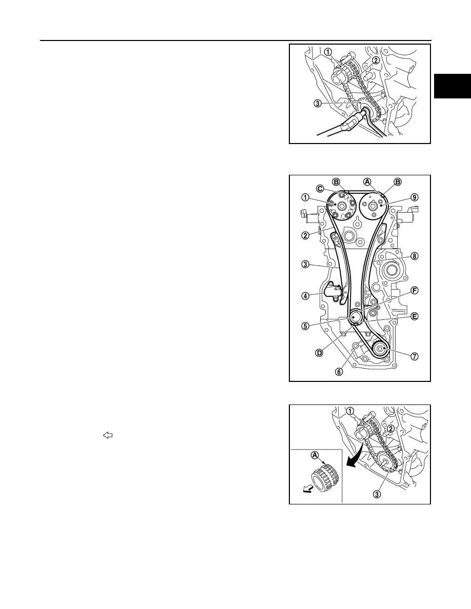
c. Remove the crankshaft sprocket (1), the oil pump drive chain

(2), and the oil pump sprocket (3) at the same time.

INSTALLATION

NOTE:

For installation follow the relationship between the matching mark on

each timing chain and that of the corresponding sprocket, with the

components installed.

1. Install the crankshaft sprocket and the oil pump drive related parts:
a. Install the crankshaft sprocket (1), the oil pump drive chain (2),

and the oil pump sprocket (3) at the same time.

• Install the crankshaft sprocket so that its invalid gear area (A)

is toward the back of the engine.

• Install the oil pump sprocket so that its protrusion faces the

front of engine.

NOTE:

There is no matching mark in the oil pump drive related parts. 

JPBIA4230ZZ

(1) : Camshaft sprocket (EXH)
(2) : Timing chain 
(3) : Timing chain slack guide
(4) : Chain tensioner
(5) : Crankshaft sprocket
(6) : Oil pump drive chain
(7) : Oil pump sprocket
(8) : Timing chain tension guide
(9) : Camshaft sprocket (INT)
(A) : Matching mark (Peripheral groove)
(B) : Pink link
(C) : Matching mark (Peripheral groove)
(D) : Orange link
(E) : Matching mark (stamp)
(F) : Crankshaft key (point straight up)

JPBIA4223ZZ

: Engine front

JPBIA5248ZZ

EM-52

< REMOVAL AND INSTALLATION >

[HR16DE]

TIMING CHAIN

b. Hold the top of the oil pump shaft using the socket (size: E8),

and then tighten the oil pump sprocket nut.

c.

Install oil pump drive chain tensioner (1).

• Insert the body into the shaft (B) while inserting the spring into

the attaching hole (A) of cylinder block front surface.

• Check that the tension is applied to the oil pump drive chain

after installing.

2. Install timing chain:

• Install by aligning matching marks on each sprocket and tim-

ing chain.

• If these matching marks are not aligned, rotate the camshaft

slightly to correct the position.

CAUTION:

• After the matching marks are aligned, keep them aligned

by holding them. 

• To avoid skipped teeth, do not rotate crankshaft and cam-

shaft until front cover is installed.

3. Install timing chain tension guide (2) and timing chain slack

guide (1).

(1) : Crankshaft sprocket
(2) : Oil pump drive chain 
(3) : Oil pump sprocket

JPBIA4230ZZ

JPBIA4143ZZ

(A) : Matching mark (Peripheral groove)
(B) : Pink link
(C) : Matching mark (Peripheral groove)
(D) : Orange link
(E) : Matching mark (stamp)
(F) : Crankshaft key (point straight up)

JPBIA4144ZZ

JPBIA4141ZZ

TIMING CHAIN

EM-53

< REMOVAL AND INSTALLATION >

[HR16DE]

C

D

E

F

G

H

I

J

K

L

M

A

EM

N

P

O

4. Install chain tensioner (1).

• Secure the plunger at the most compressed position using a

stopper pin (A), and then install it.

• Pull out the stopper pin after installing the chain tensioner.

5. Check matching mark position of timing chain and each sprocket again.
6. Install the front oil seal to the front cover. Refer to 

EM-71, "FRONT OIL SEAL : Removal and Installation"

.

7. Install front cover with the following procedure:
a. Apply a continuous bead of liquid gasket to the front cover as

shown. 

Use Genuine Silicone RTV Sealant or equivalent. Refer to

GI-21, "Recommended Chemical Products and Sealants"

.

PBIC3722E

(1) : Cylinder head
(2) : Cylinder block
(3) : Oil pan (upper)

(A)

: Liquid gasket application area [3.0 - 4.0 mm (0.12 - 0.16 in) diam-
eter]

Tool number

: WS39930000 ( — )

JPBIA4145ZZ

EM-54

< REMOVAL AND INSTALLATION >

[HR16DE]

TIMING CHAIN

b. Apply a continuous bead of liquid gasket to front cover as

shown. 

Use Genuine Silicone RTV Sealant or equivalent. Refer to

GI-21, "Recommended Chemical Products and Sealants"

.

c.

Tighten bolts in the numerical order as shown.

d. After all bolts are tightened, retighten them to specified torque in

numerical order as shown.

CAUTION:

Be sure to wipe off any excessive liquid gasket leaking to

surface.

8. Insert crankshaft pulley by aligning with crankshaft key. 

• When inserting crankshaft pulley with a plastic hammer, tap on its center portion (not circumference).

CAUTION:

Do not damage front oil seal lip section.

9. Tighten crankshaft pulley bolt:

• Secure crankshaft pulley with a suitable tool and tighten crankshaft pulley bolt.

a. Apply new engine oil to thread and seat surfaces of crankshaft pulley bolt.
b. Tighten crankshaft pulley bolt.

(1) : Front cover edge
(A) : Liquid gasket application area
(b) : 4.0 - 5.6 mm

(c)

: Liquid gasket application area [3.0 - 4.0 mm (0.12 - 0.16 in) diame-
ter]

JPBIA4146ZZ

JPBIA4139ZZ

Crankshaft pulley bolt : 35.0 N·m (3.6 kg-m, 26 ft-lb)


Content   ..  377  378  379  380   ..