Nissan Versa Sedan. Instruction - part 381


  Index      Nissan     Nissan Versa Sedan (2014 year) - Service and Repair Instruction


Search            copyright infringement  


Content   ..  379  380  381  382   ..


Nissan Versa Sedan. Instruction - part 381


CAMSHAFT

EM-59

< REMOVAL AND INSTALLATION >

[HR16DE]

C

D

E

F

G

H

I

J

K

L

M

A

EM

N

P

O

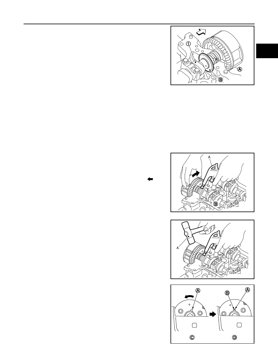
b. Apply the following air pressure to the No. 1 journal oil hole (A)

of camshaft (INT) (1) shown using an air gun.

• Apply the air pressure into the oil hole on the second groove

from the front of camshaft thrust (B).

• Proceed all the way through step “e” with the air pressure on.

• Attach the rubber nozzle narrowed to the top of the air gun to

prevent air leakage from the oil hole (A). Securely apply the air

pressure to the oil hole.

WARNING:

Eye protection should be worn as needed.

CAUTION:

• There are other oil holes in the side grooves. Do not use the incorrect oil holes.

• Be sure not to damage the oil path with the tip of the air gun.

• Wipe all the oil off the air gun to prevent oil from being blown all over along with the air, and the

area around the air gun should be wiped with a rag when applying air pressure. Eye protection

should be worn as needed.

NOTE:

The air pressure is used to move the lock pin into the disengage position.

c. Hold the camshaft sprocket (INT) with hands, and then apply the power counterclockwise/clockwise alter-

nately.

• Finally rotate the sprocket of the camshaft sprocket (INT)

counterclockwise [the direction shown by the arrow (

)].

• Perform the work while continuously applying the air pressure

to the oil hole.

• If the lock pin is not released, tap the camshaft sprocket (INT)

lightly with a plastic hammer (A).

• If the camshaft sprocket (INT) is not rotated counterclockwise

even if the above procedures are performed, check the air

pressure and the oil hole position.

d. While doing the above, once you hear a click (the sound of the

internal lock pin disengaging) from inside the camshaft sprocket

(INT), start turning the camshaft sprocket (INT) in the counter-

clockwise direction in the most advanced angle position.

• Keep the air pressure on.

• If there is no click, as soon as the vane side (camshaft side)

starts moving independently of the sprocket, the lock pin has

become disengaged.

Air pressure

: 300 kPa (3.1 kg/cm

2

, 44 psi) or more

JPBIA4150ZZ

(A) : Air gun 
(B) : Rubber nozzle

JPBIA4151ZZ

JPBIA4152ZZ

(C) : Lock pin engaged 
(D) : Most advanced angle

PBIC3684E

EM-60

< REMOVAL AND INSTALLATION >

[HR16DE]

CAMSHAFT

• Check that it is in the most advanced angle position by seeing if the stopper pin groove (A) and the stop-

per pin hole (B) are matched up as shown.

e. Stop applying air pressure and release the camshaft (INT).
f.

Insert the stopper pin (A) into the stopper pin holes in the cam-

shaft sprocket (INT) and lock in the most advanced angle posi-

tion.

CAUTION:

No load is exerted on the stopper pin (spring reaction, etc.).

Since it comes out easily, secure it with tape (B) to prevent

it from falling out.

NOTE:

The stopper pin shows one example of a hexagonal wrench for

2.5 mm (0.098 in) [length of inserted section: approximately15

mm (0.59 in)].

10. Remove the camshaft sprocket (INT):
a. Keeping the camshaft hexagonal part (A) in place with the

wrench, loosen the bolts for the camshaft sprocket (INT) (2).

CAUTION:

• Do not drop stopper pin.

• Tape (C) the stopper pin (B) so it does not come out.

• Do not subject it to impact by dropping.

• Do not disassemble. [Do not loosen the three bolts (A)].

NOTE:

While removing the camshaft sprocket (INT), if you have taken

out the stopper pin and the lock pin has been rejoined in the

most retarded angle, do the following to restore it.

i.

Install the camshaft (INT) and tighten the bolts enough to pre-

vent air from leaking out.

CAUTION:

The internal lock pin will get damaged, so keep the torque

on the bolts to the minimum required to prevent air from

escaping.

ii.

Apply the air pressure, disengage the lock pin, and turn the vane to the most advanced angle position.

iii. Insert the stopper pin.
iv. Remove camshaft sprocket (INT) from the camshaft.
11. Remove camshaft brackets (No. 2 to 5).

JPBIA4153ZZ

(1) Camshaft (INT)

JPBIA4154ZZ

PBIC3691E

CAMSHAFT

EM-61

< REMOVAL AND INSTALLATION >

[HR16DE]

C

D

E

F

G

H

I

J

K

L

M

A

EM

N

P

O

• Loosen bolts in several steps in the reverse order as shown.

NOTE:

The camshaft bracket (No. 1) has been already removed.

12. Remove camshaft (EXH).
13. Remove camshaft (INT).
14. Remove valve lifter.

• Identify installation positions, and store lifters without mixing them up.

15. Remove intake valve timing control solenoid valve (1).
16. Remove the alternator and bracket, remove the plug (2), and

then remove the oil filter. Refer to 

EM-56, "Exploded View"

.

17. Remove exhaust valve timing control solenoid valve.
18. Remove the plug on the exhaust valve timing control solenoid valve and the oil filter. Refer to 

EM-56,

"Exploded View"

.

19. For component inspection after removal, refer to 

EM-65, "Inspection"

.

INSTALLATION

CAUTION:

Do not reuse O-rings or washers.
1. Install oil filter (1) for intake and exhaust valve timing control

solenoid valves.

CAUTION:

Do not reuse washers.

NOTE:

The intake side is shown as an example.

• The oil filter (1) and washer (2) are assembled to the plug (3),

and then install them in to the cylinder head. Refer to 

EM-56,

"Exploded View"

.

2. Install intake and exhaust valve timing control solenoid valves.

• Insert it straight into the cylinder head.

• Tighten bolts.

3. Install valve lifters.

• If they are reused, install them in the original positions.

4. Put a matching mark for positioning the camshaft (INT) and the camshaft sprocket (INT): 

NOTE:

This helps prevent the knock pin from engaging with the incorrect pin hole after installing the camshaft

(INT) and the camshaft sprocket (INT).

(A) : EXH side
(B) : INT side

: Engine front

PBIC3686E

PBIC3692E

AWBIA1146GB

EM-62

< REMOVAL AND INSTALLATION >

[HR16DE]

CAMSHAFT

a. Put the matching marks (A) on a line extending from the knock

pin position of camshaft (INT) (1) front surface.

• Put the marks on the visible position with the camshaft

sprocket installed as shown. 

b. Put the matching marks on a line extending from the knock pin

hole (B) position of camshaft sprocket (INT) (2) as shown. 

• Put the marks on the visible position with it installed to the

camshaft.

5. Put a matching mark for positioning the camshaft (EXH) and the camshaft sprocket (EXH):

NOTE:

This helps prevent the knock pin from engaging with the incorrect pin hole after installing the camshaft

(INT) and the camshaft sprocket (EXH).

a. Put the matching marks (A) on a line extending from the knock

pin position of camshaft (EXH) (1) front surface.

• Put the marks on the visible position with the camshaft

sprocket installed as shown. 

b. Put the matching marks on a line extending from the knock pin

hole (B) position of camshaft sprocket (EXH) (2) as shown. 

• Put the marks on the visible position with it installed to the

camshaft.

6. Install camshaft.

• Note that the camshafts (INT and EXH) have different shapes

at the rear.

• Install camshafts to the cylinder head so that knock pins (A) on

front end are positioned as shown.

NOTE:

Though camshaft does not stop at the portion as shown for the

placement of cam nose, it is generally accepted camshaft is

placed for the same direction as shown.

PBIC3696E

JPBIA4155ZZ

(1) : Camshaft (EXH)
(2) : Camshaft (INT)
(A) : Identification mark

JPBIA4156ZZ

(1) : Camshaft (EXH)
(2) : Camshaft (INT)

: Upper side

JPBIA4157ZZ


Content   ..  379  380  381  382   ..