Nissan Versa Sedan. Instruction - part 384


  Index      Nissan     Nissan Versa Sedan (2014 year) - Service and Repair Instruction


Search            copyright infringement  


Content   ..  382  383  384  385   ..


Nissan Versa Sedan. Instruction - part 384


OIL SEAL

EM-71

< REMOVAL AND INSTALLATION >

[HR16DE]

C

D

E

F

G

H

I

J

K

L

M

A

EM

N

P

O

FRONT OIL SEAL : Removal and Installation

INFOID:0000000009266663

REMOVAL

1. Remove the following parts.

• Remove wheel and tire. Refer to 

WT-39, "Adjustment"

• Front fender protector (RH). Refer to 

EXT-26, "Removal and Installation"

.

• Drive belt. Refer to 

EM-16, "Removal and Installation"

.

• Crankshaft pulley. Refer to 

EM-47, "Exploded View"

.

2. Remove front oil seal with a suitable tool.

CAUTION:

Be careful not to damage front cover and crankshaft.

INSTALLATION

1. Apply new engine oil to new front oil seal joint surface and seal lip.
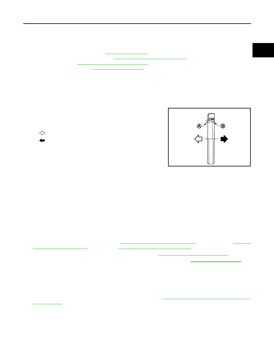
2. Install front oil seal so that each seal lip is oriented as shown. 

• Press-fit front oil seal using a suitable drift with outer diameter 50 mm (1.97 in) and inner diameter 44

mm (1.73 in).

CAUTION:

• Be careful not to damage front cover and crankshaft.

• Press-fit oil seal straight to avoid causing burrs or tilting.

3. Installation of the remaining components is in the reverse order of removal.

REAR OIL SEAL
REAR OIL SEAL : Removal and Installation

INFOID:0000000009266664

REMOVAL

1. Remove transaxle assembly. Refer to 

TM-27, "Removal and Installation"

 (M/T models), 

TM-452,

"Removal and Installation"

 (A/T models), 

TM-452, "Removal and Installation"

  (CVT models).

2. Remove clutch cover and clutch disk (M/T models). Refer to 

CL-18, "Removal and Installation"

.

3. Remove flywheel (M/T models) or drive plate (A/T or CVT models). Refer to 

EM-94, "Exploded View"

.

4. Remove rear oil seal with a suitable tool.

CAUTION:

Be careful not to damage crankshaft and cylinder block.

INSTALLATION

1. Apply the liquid gasket lightly to entire outside area of new rear oil seal.

Use Genuine Silicone RTV Sealant or equivalent. Refer to 

GI-21, "Recommended Chemical Products

and Sealants"

.

(A)

: Dust seal lip

(B)

: Oil seal lip

: Engine outside

: Engine inside

PBIC3485J

EM-72

< REMOVAL AND INSTALLATION >

[HR16DE]

OIL SEAL

2. Install rear oil seal so that each seal lip is oriented as shown.

• Press-fit rear oil seal with a suitable drift (A) outer diameter

113 mm (4.45 in) and inner diameter 90 mm (3.54 in).

CAUTION:

• Be careful not to damage crankshaft and cylinder block.

• Press-fit oil seal straight to avoid causing burrs or tilt-

ing.

• Do not touch grease applied onto oil seal lip.

• Press in rear oil seal (1) to the position as shown.

3. Installation of the remaining components is in the reverse order of removal.

(A)

: Dust seal lip

(B)

: Oil seal lip

: Engine outside

: Engine inside

PBIC3485J

PBIC3660E

(A)

: Rear end surface of cylinder block

(b)

: 0 - 0.5 mm (0 - 0.020 in)

PBIC3149J

CYLINDER HEAD

EM-73

< REMOVAL AND INSTALLATION >

[HR16DE]

C

D

E

F

G

H

I

J

K

L

M

A

EM

N

P

O

CYLINDER HEAD

Exploded View

INFOID:0000000009266665

Cylinder Head Bolts

Valve Components

JPBIA4097ZZ

1.

Cylinder head assembly

2.

Cylinder head bolt

3.

Washer

4.

Cylinder head gasket

A. Refer to 

EM-74

JPBIA4098GB

1.

Spark plug

2.

Valve collet

3.

Valve spring retainer

4.

Valve spring

5.

Valve spring seat

6.

Valve oil seal

EM-74

< REMOVAL AND INSTALLATION >

[HR16DE]

CYLINDER HEAD

Removal and Installation

INFOID:0000000009266666

REMOVAL

NOTE:

When removing components such as hoses, tubes/lines, etc., cap or plug openings to prevent fluid from spill-

ing.
1. Release fuel pressure. Refer to 

EC-133, "Work Procedure"

.

2. Remove the following components and related parts.

• Air duct. Refer to 

EM-25, "Removal and Installation"

.

• Fuel tube and fuel injector. Refer to 

EM-37, "Exploded View"

.

• Water outlet. Refer to 

CO-25, "Removal and Installation"

.

• Exhaust manifold. Refer to 

EM-30, "Exploded View"

.

• Front cover and timing chain. Refer to 

EM-47, "Exploded View"

.

• Camshaft. Refer to 

EM-56, "Exploded View"

.

3. Remove cylinder head loosening bolts in reverse order as

shown. 

4. Remove cylinder head gasket.

INSTALLATION

1. Install new cylinder head gasket.
2. Tighten cylinder head bolts in numerical order as shown.

CAUTION:

If cylinder head bolts are reused, check their outer diame-

ters before installation. Refer to 

EM-76, "Inspection"

.

a. Apply new engine oil to threads and seating surfaces of bolts.
b. Tighten all bolts.

7.

Valve guide (INT)

8.

Valve guide (EXH)

9.

Valve seat (EXH)

10. Valve (EXH)

11. Valve (INT)

12. Valve seat (INT)

A.

Refer to 

EM-75

(A) : EXH side
(B) : INT side

: Engine front

PBIC3732E

(A) : EXH side
(B) : INT side

: Engine front

Cylinder head bolts

: 40.0 N·m (4.1 kg-m, 30 ft-lb)

PBIC3732E


Content   ..  382  383  384  385   ..