Nissan Versa Sedan. Instruction - part 367


  Index      Nissan     Nissan Versa Sedan (2014 year) - Service and Repair Instruction


Search            copyright infringement  


Content   ..  365  366  367  368   ..


Nissan Versa Sedan. Instruction - part 367


PRECAUTIONS

EM-3

< PRECAUTION >

[HR16DE]

C

D

E

F

G

H

I

J

K

L

M

A

EM

N

P

O

PRECAUTION

PRECAUTIONS

Precaution for Supplemental Restraint System (SRS) "AIR BAG" and "SEAT BELT 
PRE-TENSIONER"

INFOID:0000000009266621

The Supplemental Restraint System such as “AIR BAG” and “SEAT BELT PRE-TENSIONER”, used along

with a front seat belt, helps to reduce the risk or severity of injury to the driver and front passenger for certain

types of collision. This system includes seat belt switch inputs and dual stage front air bag modules. The SRS

system uses the seat belt switches to determine the front air bag deployment, and may only deploy one front

air bag, depending on the severity of a collision and whether the front occupants are belted or unbelted.

Information necessary to service the system safely is included in the SR and SB section of this Service Man-

ual.

WARNING:

• To avoid rendering the SRS inoperative, which could increase the risk of personal injury or death in

the event of a collision which would result in air bag inflation, all maintenance must be performed by

an authorized NISSAN/INFINITI dealer.

• Improper maintenance, including incorrect removal and installation of the SRS, can lead to personal

injury caused by unintentional activation of the system. For removal of Spiral Cable and Air Bag

Module, see the SR section.

• Do not use electrical test equipment on any circuit related to the SRS unless instructed to in this

Instruction. SRS wiring harnesses can be identified by yellow and/or orange harnesses or har-

ness connectors.

PRECAUTIONS WHEN USING POWER TOOLS (AIR OR ELECTRIC) AND HAMMERS

WARNING:

• When working near the Airbag Diagnosis Sensor Unit or other Airbag System sensors with the Igni-

tion ON or engine running, DO NOT use air or electric power tools or strike near the sensor(s) with a

hammer. Heavy vibration could activate the sensor(s) and deploy the air bag(s), possibly causing

serious injury.

• When using air or electric power tools or hammers, always switch the Ignition OFF, disconnect the

battery, and wait at least 3 minutes before performing any service.

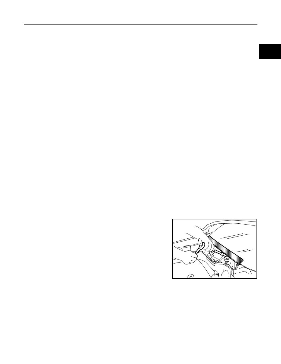
Precaution for Procedure without Cowl Top Cover

INFOID:0000000009266622

When performing the procedure after removing cowl top cover, cover

the lower end of windshield with urethane, etc.

Draining Engine Coolant

INFOID:0000000009266623

Drain engine coolant and engine oil when the engine is cooled.

Disconnecting Fuel Piping

INFOID:0000000009266624

• Before starting work, check no fire or spark producing items are in the work area. 

• Release fuel pressure before disconnecting and disassembly.

• After disconnecting pipes, plug openings to stop fuel leakage.

PIIB3706J

EM-4

< PRECAUTION >

[HR16DE]

PRECAUTIONS

Removal and Disassembly

INFOID:0000000009266625

• When instructed to use SST, use specified tools. Always be careful to work safely, avoid forceful or unin-

structed operations. 

• Use care to avoid damage to mating or sliding surfaces.

• Dowel pins are used for several parts alignment. When replacing and reassembling parts with dowel pins,

check that dowel pins are installed in the original position.

• Cover openings of engine system with a tape or equivalent, if necessary, to seal out foreign materials.

• Mark and arrange disassembly parts in an organized way for easy troubleshooting and reassembly.

• When loosening nuts and bolts, start with the one furthest outside, then the one diagonally opposite, and so

on. If the order of loosening is specified, do exactly as specified. Power tools may be used in the step.

Inspection, Repair and Replacement

INFOID:0000000009266626

Before repairing or replacing, thoroughly inspect parts. Inspect new replacement parts in the same way, and

replace if necessary.

Assembly and Installation

INFOID:0000000009266627

• Use torque wrench to tighten bolts or nuts to specification.

• Tighten nuts and bolts in order exactly as specified in the procedure. If a tightening order or procedure is not

specified, tighten nuts and bolts equally in several different steps. Start with the nuts or bolts in the center

and then tighten diagonally starting with the inside and moving to the outside in a spiral pattern.

• Replace with new gasket, packing, oil seal or O-ring.

• Thoroughly wash, clean, and air-blow each part. Carefully check engine oil or engine coolant passages for

restrictions and blockages. 

• Avoid damaging sliding or mating surfaces. Before assembling, completely remove foreign materials such

as cloth lint or dust, and oil the sliding surfaces. 

• After refilling engine coolant, bleed the air from the cooling system.

• After repairing, start the engine and increase engine speed to check for engine coolant leaks, fuel leaks,

engine oil leaks, and exhaust gas leaks. 

Parts Requiring Angle Tightening

INFOID:0000000009266628

• For the final tightening of the following engine parts use Tool: 

- Camshaft sprocket (INT) bolt

- Cylinder head bolts

- Main bearing cap bolts

- Connecting rod cap bolts

- Crankshaft pulley bolt (Note an angle wrench is required as bolt flange is provided with notches for angle

tightening)

• Do not use a torque value for final tightening. 

• The torque value for these parts are for a preliminary step.

• Ensure thread and seat surfaces are clean and coated with engine oil. 

Precaution for Liquid Gasket

INFOID:0000000009266629

REMOVAL OF LIQUID GASKET SEALANT

• After removing the bolts and nuts, separate the mating surface and

remove the old liquid gasket sealant using Tool.

CAUTION:

Do not damage mating surfaces.

• Tap the seal cutter to insert it (1).

• In areas where the Tool is difficult to use, lightly tap to slide it (2).

Tool number : KV10112100 (BT-8653-A)

Tool number

: KV10111100 (J-37228)

WBIA0566E

PRECAUTIONS

EM-5

< PRECAUTION >

[HR16DE]

C

D

E

F

G

H

I

J

K

L

M

A

EM

N

P

O

LIQUID GASKET APPLICATION PROCEDURE

1. Remove the old liquid gasket adhering to the gasket application

surface and the mating surface using suitable tool.

• Remove the liquid gasket completely from the groove of the

liquid gasket application surface, bolts, and bolt holes.

2. Thoroughly clean the mating surfaces and remove adhering

moisture, grease and foreign material.

3. Attach the liquid gasket tube to the suitable tool.

Use Genuine RTV Silicone Sealant or equivalent. Refer to

GI-21, "Recommended Chemical Products and Sealants"

4. Apply the liquid gasket without breaks to the specified location

with the specified dimensions.

• If there is a groove for the liquid gasket application, apply the

liquid gasket to the groove.

• Normally apply the liquid gasket on the inside edge of the bolt

holes. Also apply to the outside edge of the bolt holes when

specified in the procedure.

• Within five minutes of liquid gasket application, install the mat-

ing component.

• If the liquid gasket protrudes, wipe it off immediately.

• Do not retighten after the installation.

• Wait 30 minutes or more after installation before refilling the

engine with oil or coolant.

CAUTION:

Carefully follow all of the warnings, cautions, notes, and procedures contained in this instruction.

PBIC0003E

WBIA0567E

SEM159F

EM-6

< PREPARATION >

[HR16DE]

PREPARATION

PREPARATION

PREPARATION

Special Service Tools

INFOID:0000000009266630

The actual shapes of Kent-Moore tools may differ from those of special service tools illustrated here.

Tool number
(Kent-Moore No.)
Tool name

Description

KV10111100
(J-37228)
Seal cutter

Removing oil pan (lower and upper) etc.

KV10116200
(J-26336-B)
Valve spring compressor
1. KV10115900
(J-26336-20)
Attachment
2. KV10109220
(   —   )
Adapter

Disassembling and assembling valve mecha-
nism
Part (1) is a component of KV10116200, but 
Part (2) is not so.

KV10112100
(BT-8653-A)
Angle wrench

Tightening bolts for main bearing cap, cylinder 
head, etc. 

KV10117100
(   —   )
Heated oxygen sensor wrench

Loosening or tightening heated oxygen sen-
sor 1
For 22 mm (0.87 in) width hexagon nut

KV10107902
(J-38959)
Valve oil seal puller

Removing valve oil seal

KV10115600
(J-38958)
Valve oil seal drift

Installing valve oil seal
Use side A.
a: 20 (0.79) dia. d: 8 (0.31) dia.
b: 13 (0.51) dia. e: 10.7 (0.421)
c: 10.3 (0.406) dia.    f: 5 (0.20)
                                                   Unit: mm (in)

S-NT046

PBIC1650E

S-NT014

NT379

NT011

S-NT603


Content   ..  365  366  367  368   ..