Nissan Versa Sedan. Instruction - part 366
ECM
EC-463
< REMOVAL AND INSTALLATION >
[HR16DE]
C
D
E
F
G
H
I
J
K
L
M
A
EC
N
P
O
REMOVAL AND INSTALLATION
ECM
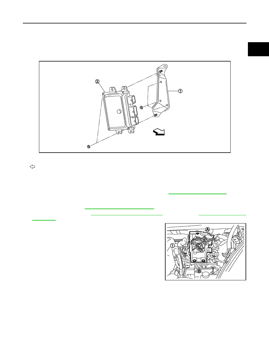
Exploded View
INFOID:0000000009267332
Removal and Installation
INFOID:0000000009267333
CAUTION:
Perform ADDITIONAL SERVICE WHEN REPLACING ECM. Refer to
.
REMOVAL
1. Remove battery. Refer to
PG-63, "Removal and Installation"
PCS-30, "Removal and Installation"
(WITH I-KEY) or
(WITHOUT I-KEY).
3. Remove IPDM E/R cover (1).
4. Disconnect ECM harness connectors.
5. Remove ECM mounting nuts.
6. Remove ECM from ECM bracket.
INSTALLATION
Install in the reverse order of removal.
1.
ECM bracket
2.
ECM
: Vehicle front
JSBIA0333ZZ
A : mounting nut
B : mounting bolts
JSBIA0473ZZ