Nissan Versa Sedan. Instruction - part 368


  Index      Nissan     Nissan Versa Sedan (2014 year) - Service and Repair Instruction


Search            copyright infringement  


Content   ..  366  367  368  369   ..


Nissan Versa Sedan. Instruction - part 368


PREPARATION

EM-7

< PREPARATION >

[HR16DE]

C

D

E

F

G

H

I

J

K

L

M

A

EM

N

P

O

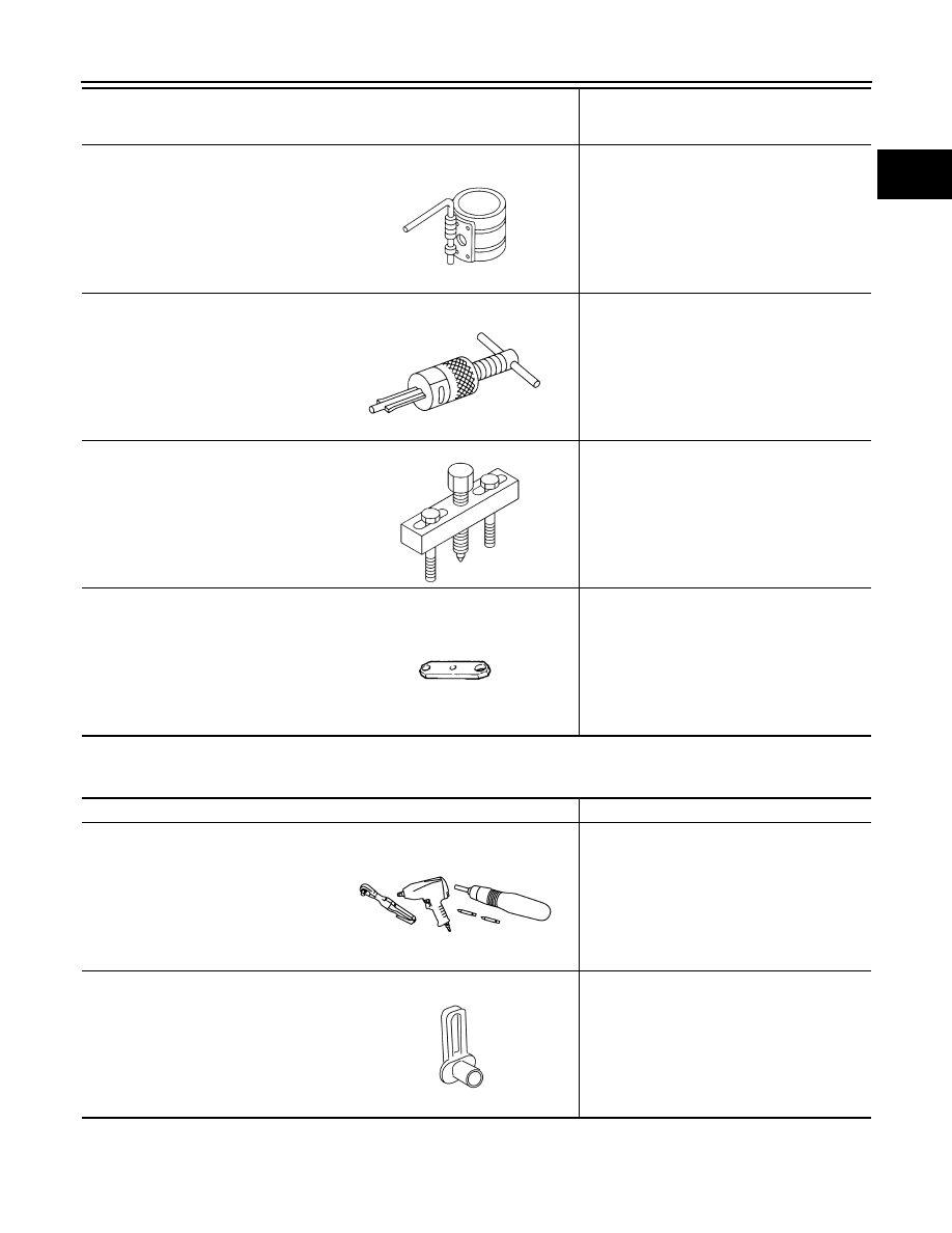
Commercial Service Tools

INFOID:0000000009266631

EM03470000
(J-8037)
Piston ring compressor

Installing piston assembly into cylinder bore

ST16610001
(J-23907)
Pulley puller

Removing pilot converter

KV11103000
(   —   )
Pulley puller

Removing crankshaft pulley

KV11105210
(J-44716)
Stopper plate

Holding drive plate and flywheel static   

Tool number
(Kent-Moore No.)
Tool name

Description

S-NT044

S-NT045

NT676

ZZA0009D

Tool name

Description

Power tool

Loosening nuts, screws and bolts

Quick connector release

Removing fuel tube quick connectors in en-
gine room

PIIB1407E

PBIC0198E

EM-8

< PREPARATION >

[HR16DE]

PREPARATION

Spark plug wrench

Removing and installing spark plug
a: 14 mm (0.55 in)

Pulley holder

Crankshaft pulley removing and installing

Valve seat cutter set

Finishing valve seat dimensions

Piston ring expander

Removing and installing piston ring

Valve guide drift

Removing and installing valve guide

Valve guide reamer

(1): Reaming valve guide inner hole
(2): Reaming hole for oversize valve guide 

(J-43897-18)
(J-43897-12)
Oxygen sensor thread cleaner

Reconditioning the exhaust system threads 
before installing a new air fuel ratio sensor 
(Use with anti-seize lubricant shown below.)
A: [18 mm (0.71 in) dia.] for zirconia heated 
oxygen sensor
B: [12 mm (0.47 in) dia.] for titania heated 
oxygen sensor
C: Mating surface shave cylinder
D: Flutes

Tool name

Description

JPBIA0399ZZ

NT035

S-NT048

S-NT030

PBIC4012E

PBIC4013E

JPBIA0238ZZ

PREPARATION

EM-9

< PREPARATION >

[HR16DE]

C

D

E

F

G

H

I

J

K

L

M

A

EM

N

P

O

Acoustic tension gauge

Checking drive belt tension

Anti-seize lubricant (Permatex 133AR 
or equivalent meeting MIL specifica-
tion MIL-A-907)

Lubricating oxygen sensor thread cleaning 
tool when reconditioning exhaust system 
threads

Instruction lift table caddy

Removing and installing engine 

1. Compression gauge
2. Adapter

Checking compression pressure

Tube presser

Pressing the tube of liquid gasket

Tool name

Description

PBIC3881E

AEM489

ZZA1210D

ZZA0008D

S-NT052

EM-10

< BASIC INSPECTION >

[HR16DE]

CAMSHAFT VALVE CLEARANCE

BASIC INSPECTION

CAMSHAFT VALVE CLEARANCE

Inspection and Adjustment

INFOID:0000000009266632

INSPECTION

Perform inspection as follows after removal, replacement or installation of camshaft or valve-related parts, or if

there are unusual engine conditions regarding valve clearance. 
1. Remove rocker cover. Refer to 

EM-44, "Removal and Installation"

.

2. Measure the valve clearance with the following procedure:
a. Set No. 1 cylinder at TDC of its compression stroke.

• Rotate crankshaft pulley (2) clockwise and align TDC mark (no

paint) (A) to timing indicator (1) on front cover.

• At the same time, check that both intake and exhaust cam

lobes of No. 1 cylinder face inside (

) as shown.

• If the lobes do not face inside, rotate the crankshaft pulley 360

degrees to align as shown.

b. Use a feeler gauge (A) to measure the clearance between the

valve lifter and camshaft. 

(B)

: White paint mark (Not used for service)

PBIC3673E

(1)

: Camshaft (INT)

(2)

: Camshaft (EXH)

: Engine front

JPBIA4738ZZ

Valve clearance

: Refer to 

EM-118, "Camshaft"

.

JPBIA4116ZZ


Content   ..  366  367  368  369   ..