Nissan Qashqai (2007-2010). Manual - part 683
BRAKE BOOSTER
BR-31
< ON-VEHICLE REPAIR >
[LHD]
C
D
E
G
H
I
J
K
L
M
A
B
BR
N
O
P
Note the following, and installation is the reverse order of removal.
CAUTION:
• Be careful not to damage brake booster stud bolt threads. If brake booster is tilted during installa-
tion, the dash panel may damage the threads.
• Never deform or bend the brake tubes when installing the brake booster.
• Always use a new gasket between the brake booster and the spacer.
• Replace the clevis pin if it is damaged. Refer to
BR-18, "Inspection and Adjustment"
• After installation, perform the air bleeding. Refer to
BR-12, "Bleeding Brake System"
.
CAUTION:
Never reuse drained brake fluid.
Inspection and Adjustment
INFOID:0000000000925808
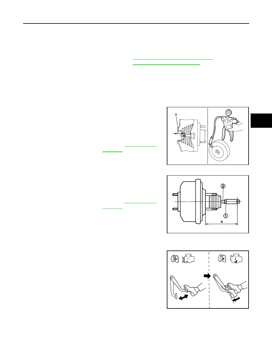
INSPECTION AFTER REMOVAL
Output Rod Length Inspection
1.
With a handy vacuum pomp, apply vacuum pressure of
−
66.7
kPa (
−
500 mmHg,
−
19.70 inHg,
−
0.667 bar) to the brake
booster.
2.
Check the output rod length (A).
Input Rod Length Inspection
1.
Loosen the lock nut (1) and adjust the input rod (2) to the speci-
fied length (B).
2.
Tighten the lock nut to the specified torque.
INSPECTION AFTER INSTALLATION
Operation
Depress the brake pedal several times at 5-second intervals with the
engine stopped. Start the engine with the brake pedal fully
depressed. Check that the clearance between brake pedal and dash
lower pane decreases.
NOTE:
A slight impact with a small click may be felt on the pedal when the
brake pedal is fully depressed. This is a normal phenomenon due to
the brake system operation.
Air Tight
Standard
Output rod length (A)
: Refer to
.
JPFIA0021ZZ
Standard
Input rod length (B)
: Refer to
.
JPFIA0020ZZ
BRA0037D