Nissan Qashqai (2007-2010). Manual - part 684


  Index      Nissan     Nissan Qashqai - service and repair manual 2007 - 2010 year


Search            copyright infringement  


Content   ..  682  683  684  685   ..


Nissan Qashqai (2007-2010). Manual - part 684


VACUUM LINES

BR-35

< ON-VEHICLE REPAIR >

[LHD]

C

D

E

G

H

I

J

K

L

M

A

B

BR

N

O

P

K9K MODELS : Inspection

INFOID:0000000000938028

INSPECTION AFTER REMOVAL

Appearance

Check for correct assembly, damage and deterioration.

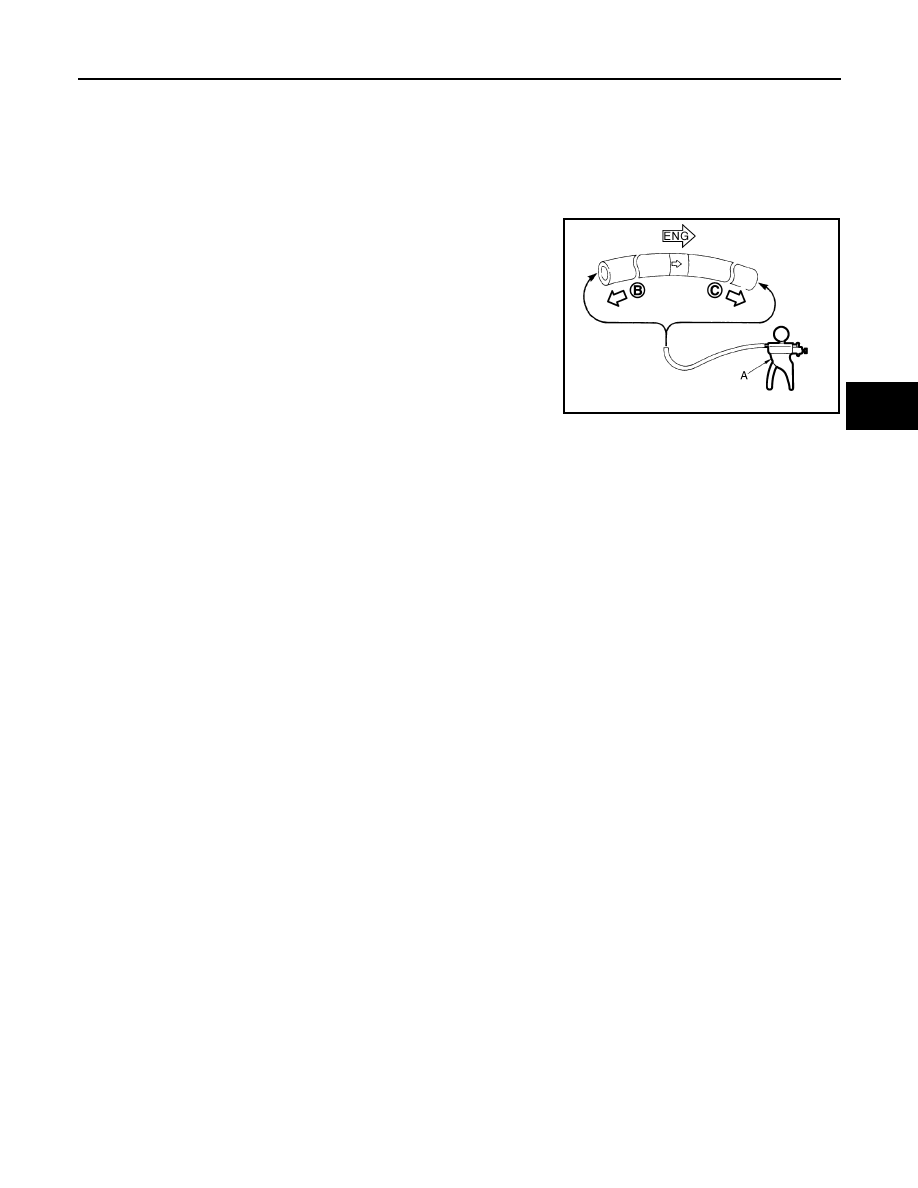
Check Valve Airtightness

• Use a handy vacuum pump (A) to check.

• Replace vacuum hose assembly if vacuum hose and check valve

are malfunctioning.

When connected to the brake booster side (B):

Vacuum should decrease within 1.3 kPa (10 mm-
Hg, 0.39 inHg, 0.013 bar) for 15 seconds under a 
vacuum of 

66.7 kPa (

500 mmHg, 

19.70 inHg, 

0.667 bar).

When connected to the engine side (C):              

Vacuum should not exist.

JPFIA0024ZZ

BR-36

< ON-VEHICLE REPAIR >

[LHD]

FRONT DISC BRAKE

FRONT DISC BRAKE

BRAKE PAD

BRAKE PAD : Exploded View

INFOID:0000000000925818

Refer to 

BR-37, "BRAKE CALIPER ASSEMBLY : Exploded View"

.

BRAKE PAD : Removal and Installation

INFOID:0000000000925819

REMOVAL

WARNING:

Clean any dust from the brake caliper and brake pads with a vacuum dust collector. Never blow with
compressed air.

CAUTION:

• Never depress the brake pedal while removing the brake pads because the piston may pop out.
• Never spill or splash brake fluid on the disc rotor.

1.

Remove tires.

2.

Remove lower sliding pin bolt.

3.

Suspend the cylinder body with suitable wire so that the brake hose will not stretch. Then remove the
brake pad from the torque member.

CAUTION:

• Never deform the pad retainer when removing the pad retainer from the torque member. 
• Never damage the piston boot.
• Never drop the brake pads, shims, and the shim covers.

INSTALLATION

WARNING:

Clean any dust from the brake caliper and brake pads with a vacuum dust collector. Never blow with
compressed air.

CAUTION:

• Never depress the brake pedal while removing the brake pads or the cylinder body because the pis-

ton may pop out.

• Never spill or splash brake fluid on the disc rotor.
1.

Install the pad retainer to the torque member if the pad retainers has been removed.

CAUTION:

• Securely assemble the pad retainers so that it will not be lifted up from the torque member.
• Never deform the pad retainers.

2.

Apply copper based brake grease to the mating faces between the pads, shims and shim covers, and
install them to the brake pad.

CAUTION:

Always replace the shims together with the shim covers when replacing the brake pad.

3.

Install the cylinder body and brake pads to the torque member.

CAUTION:

• Never damage the piston boot.
• When replacing a pad with new one, check a brake fluid level in the reservoir tank because brake

fluid returns to master cylinder reservoir tank when pressing piston in.

NOTE:
Use a disc brake piston tool to easily press piston. 

4.

Install the lower sliding pin bolt and tighten it to the specified torque.

5.

Depress the brake pedal several times to check that no drag feel is present for the front disc brake.

6.

Install tires.

BRAKE PAD : Inspection and Adjustment

INFOID:0000000000925820

INSPECTION AFTER REMOVAL

Replace the shims and the shim covers if rust is excessively attached.

ADJUSTMENT AFTER INSTALLATION

FRONT DISC BRAKE

BR-37

< ON-VEHICLE REPAIR >

[LHD]

C

D

E

G

H

I

J

K

L

M

A

B

BR

N

O

P

Brake Burnishing Procedure

Burnish contact surfaces between pads according to following procedure after refinishing or replacing pads, or
if a soft pedal occurs at very low mileage.

CAUTION:

• Be careful of vehicle speed because the brake does not operate easily until pads and disc rotor are

securely fitted.

• Only perform this procedure under safe road and traffic conditions. Use extreme caution.

1.

Drive vehicle on straight, flat road.

2.

Depress brake pedal with the power to stop vehicle within 3 to 5 seconds until the vehicle stops.

3.

Drive without depressing brake for a few minutes to cool the brake.

4.

Repeat steps 1 to 3 until pad and disc rotor are securely fitted.

BRAKE CALIPER ASSEMBLY

BRAKE CALIPER ASSEMBLY : Exploded View

INFOID:0000000000925825

BRAKE CALIPER ASSEMBLY : Removal and Installation

INFOID:0000000000925826

REMOVAL

WARNING:

Clean any dust from the brake caliper and brake pads with a vacuum dust collector. Never blow with
compressed air.

CAUTION:

Never depress the brake pedal. Brake fluid may splash while removing the brake hose.
1.

Remove tires.

1.

Brake hose

2.

Union bolt

3.

Copper washer

4.

Cap

5.

Bleeder valve

6.

Cylinder body

7.

Sliding pin

8.

Sliding pin boot

9.

Bushing

10.

Piston seal

11.

Piston

12.

Piston boot

13.

Torque member

14.

Inner shim cover

15.

Inner shim

16.

Inner pad

17.

Pad retainer

18.

Outer pad

19.

Outer shim

20.

Outer shim cover

1: Apply rubber grease.

2: Apply copper based brake grease.

: Apply brake fluid.

Refer to 

GI-4, "Components"

 for symbols not described on the above.

JPFIA0090GB

BR-38

< ON-VEHICLE REPAIR >

[LHD]

FRONT DISC BRAKE

2.

Fix the disc rotor using wheel nuts.

3.

Drain brake fluid. Refer to 

BR-11, "Draining"

.

CAUTION:

Never spill or splash brake fluid on the disc rotor.

4.

Remove union bolt, and then disconnect brake hose from caliper assembly.

5.

Remove torque member mounting bolts, and remove brake cali-
per assembly.

CAUTION:

Never drop brake pads and caliper assembly.

6.

Remove disc rotor.

CAUTION:

• Put matching marks on the wheel hub and bearing assem-

bly and the disc rotor before removing the disc rotor.

• Never drop disc rotor.

INSTALLATION

WARNING:

Clean any dust from the brake caliper and brake pads with a vacuum dust collector. Never blow with
compressed air.

CAUTION:

Never depress the brake pedal. Brake fluid may splash while removing the brake hose.

1.

Install disc rotor.

CAUTION:

Align the matching marks made during removal when reusing the disc rotor.

2.

Install the brake caliper assembly to the vehicle and tighten the torque member mounting bolts to the
specified torque.

CAUTION:

Never spill or splash any grease and moisture on the brake caliper assembly mounting face,
threads, mounting bolts and washers. Wipe out any grease and moisture.

3.

Install brake hose to brake caliper assembly, and tighten union bolts to the specified torque.

4.

Refill with new brake fluid and perform the air bleeding. Refer to 

BR-12, "Bleeding Brake System"

.

CAUTION:

• Never reuse drained brake fluid.
• Never spill or splash brake fluid on the disc rotor.

5.

Check that no drag feel is present for the front disc brake.

6.

Install tires.

BRAKE CALIPER ASSEMBLY : Disassembly and Assembly

INFOID:0000000000925827

DISASSEMBLY

NOTE:
Never remove the torque member, brake pads, shims, shim covers and pad retainers when disassembling and
assembling the cylinder body.
1.

Remove the sliding pin bolts, and remove the cylinder body from the torque member.

CAUTION:

Never drop pads, shims, shim covers and pad retainers from torque member.

2.

Remove sliding pins and sliding pin boots from torque member.

3.

Remove bushing from sliding pin.

JPFIA0030ZZ


Content   ..  682  683  684  685   ..