Nissan Qashqai (2007-2010). Manual - part 682
BRAKE MASTER CYLINDER
BR-27
< ON-VEHICLE REPAIR >
[LHD]
C
D
E
G
H
I
J
K
L
M
A
B
BR
N
O
P
BRAKE MASTER CYLINDER
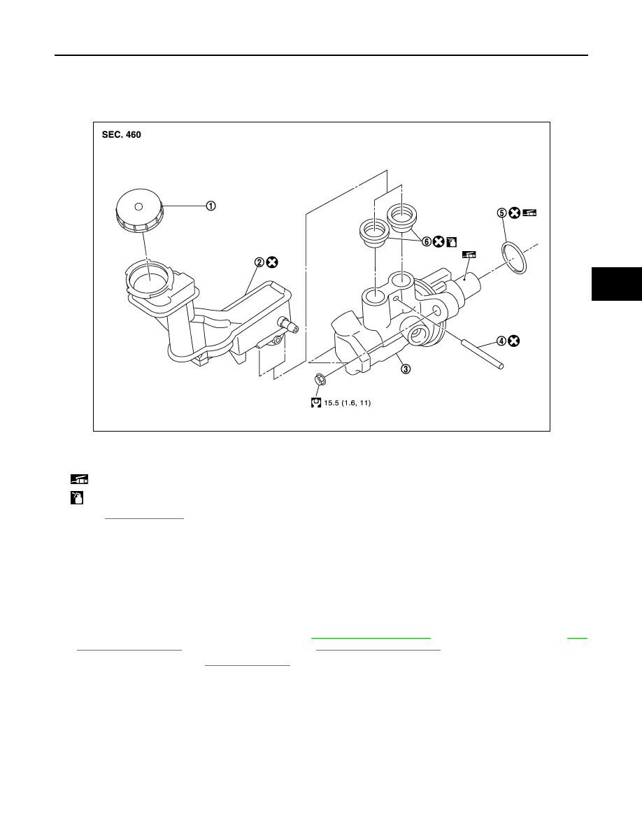
Exploded View
INFOID:0000000000925798
Removal and Installation
INFOID:0000000000925799
REMOVAL
CAUTION:
Never spill or splash brake fluid on painted surfaces. Brake fluid may seriously damage paint. Wipe it
off immediately and wash with water if it gets on a painted surface.
1.
Remove battery and bracket.
2.
Remove air duct and air cleaner case. Refer to
3.
Drain brake fluid. Refer to
4.
Separate the brake fluid level switch harness connector.
5.
Separate the brake tubes from the master cylinder assembly with a flare nut wrench.
CAUTION:
Never scratch the flare nut and the brake tube.
6.
Remove the master cylinder assembly.
CAUTION:
• Depress the brake pedal several times to release the vacuum pressure from the brake booster.
Then remove the master cylinder assembly.
• Never depress the brake pedal after the master cylinder assembly is removed.
1.
Reservoir cap
2.
Reservoir tank
3.
Cylinder body
4.
Pin
5.
O-ring
6.
Grommet
: Apply PBC (Poly Butyl Cuprysil) grease or silicone-based grease.
: Apply brake fluid.
Refer to
for symbols not described on the above.
JPFIA0080GB