Nissan Qashqai (2007-2010). Manual - part 681


  Index      Nissan     Nissan Qashqai - service and repair manual 2007 - 2010 year


Search            copyright infringement  


Content   ..  679  680  681  682   ..


Nissan Qashqai (2007-2010). Manual - part 681


BRAKE PIPING

BR-23

< ON-VEHICLE REPAIR >

[LHD]

C

D

E

G

H

I

J

K

L

M

A

B

BR

N

O

P

FRONT BRAKE (WITH ESP) : Removal and Installation

INFOID:0000000000938015

REMOVAL

CAUTION:

Never spill or splash brake fluid on painted surfaces. Brake fluid may seriously damage paint. Wipe it
off immediately and wash with water if it gets on a painted surface.
1.

Remove tires.

2.

Drain brake fluid. Refer to 

BR-11, "Draining"

.

3.

Loosen the flare nut with a flare nut wrench and separate the brake tube from the hose.

CAUTION:

• Never scratch the flare nut and the brake tube.
• Never bend sharply, twist or strongly pull out the brake hoses and tubes.
• Cover open end of brake tubes and hoses when disconnecting to prevent entrance of dirt.

4.

Remove the union bolt and remove the brake hose from the brake caliper assembly.

5.

Remove the lock plate and remove the brake hose.

INSTALLATION

CAUTION:

Never spill or splash brake fluid on painted surfaces. Brake fluid may seriously damage paint. Wipe it
off immediately and wash with water if it gets on a painted surface.
1.

Assemble the union bolt and the copper washer to the brake hose.

CAUTION:

Never reuse the copper washer.
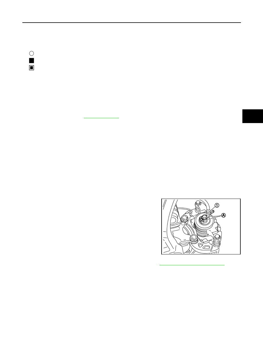
2.

Align the brake hose pin to the projection (A) of the brake caliper
assembly and tighten the union bolt (1) to the specified torque.

3.

Install the brake tube to the brake hose, temporarily tighten the
flare nut by hand until it does not rotate further, and fix the brake
hose to the bracket with the lock plate.

CAUTION:

Check that all brake hoses and tubes are not twisted and
bent.

4.

Tighten the flare nut to the specified torque with a flare nut
torque wrench.

CAUTION:

Never scratch the flare nut and the brake tube.

5.

Refill with new brake fluid and perform the air bleeding. Refer to 

BR-12, "Bleeding Brake System"

.

CAUTION:

Never reuse drained brake fluid.

6.

Install tires.

FRONT BRAKE (WITH ESP) : Inspection

INFOID:0000000000938016

INSPECTION AFTER INSTALLATOIN

1.

Check the brake hoses and tubes for the following: no scratches; no twist and deformation; no interfer-
ence with other components when steering the steering wheel; no looseness at connections.

2.

Depress the brake pedal with a force of 785 N (80 kg, 176 lb) and hold down the pedal for approximately
5 seconds with the engine running. Check for any fluid leakage.

1.

ABS actuator and electric unit (con-
trol unit)

2.

Front disc brake

3.

Master cylinder assembly

4.

Brake booster

5.

Connector

6.

Rear disc brake

A.

Brake tube

B.

Brake hose

 : Flare nut

 : Union bolt

 : Connector

JPFIA0099ZZ

BR-24

< ON-VEHICLE REPAIR >

[LHD]

BRAKE PIPING

CAUTION:

Retighten the applicable connection to the specified torque and repair any abnormal (damaged,
worn or deformed) part if any brake fluid leakage is present.

REAR BRAKE

REAR BRAKE : Exploded View

INFOID:0000000000925794

REAR BRAKE : Hydraulic Piping

INFOID:0000000000925795

1.

Brake tube

2.

Lock plate

3.

Brake hose

4.

Union bolt

A.

To front brake tube

B.

To rear brake hose

C.

Floor side

D.

Caliper side

Refer to 

GI-4, "Components"

 for symbols in the figure.

JPFIA0077GB

BRAKE PIPING

BR-25

< ON-VEHICLE REPAIR >

[LHD]

C

D

E

G

H

I

J

K

L

M

A

B

BR

N

O

P

REAR BRAKE : Removal and Installation

INFOID:0000000000925796

REMOVAL

CAUTION:

Never spill or splash brake fluid on painted surfaces. Brake fluid may seriously damage paint. Wipe it
off immediately and wash with water if it gets on a painted surface.

1.

Remove tires.

2.

Drain brake fluid. Refer to 

BR-11, "Draining"

.

3.

Loosen the flare nut with a flare nut wrench and separate the brake tube from the hose.

CAUTION:

• Never scratch the flare nut and the brake tube.
• Never sharply bend, twist or strongly pull the brake hoses and tubes.
• Cover the open end of brake tubes and hoses when disconnecting to prevent entrance of dirt.

4.

Remove the union bolt and remove the brake hose from the brake caliper assembly.

5.

Remove the lock plate and remove the brake hose from the vehicle.

INSTALLATION

CAUTION:

Never spill or splash brake fluid on painted surfaces. Brake fluid may seriously damage paint. Wipe it
off immediately and wash with water if it gets on a painted surface.
1.

Assemble the union bolt and the copper washer to the brake hose.

CAUTION:

Never reuse copper washer.

1.

ABS actuator and electric unit (con-
trol unit)

2.

Front disc brake

3.

Master cylinder

4.

Brake booster

5.

Connector

6.

Rear disc brake

A.

Brake tube

B.

Brake hose

 : Flare nut

 : Union bolt

 : Connector

JPFIA0078ZZ

BR-26

< ON-VEHICLE REPAIR >

[LHD]

BRAKE PIPING

2.

Install the brake hose L-pin by aligning it with the brake caliper
assembly positioning hole, and tighten the union bolt (1) to the
specified torque.

3.

Connect the hose to the brake tube, temporarily tighten the flare
nut by hand until it does not rotate further, and fix the brake hose
to the bracket with the lock plate.

CAUTION:

Check that the brake hoses and tubes are not twisted and
bent.

4.

Tighten the flare nut to the specified torque with a flare nut
torque wrench.

CAUTION:

Never scratch the flare nut and the brake tube.

5.

Refill with new brake fluid and perform the air bleeding. Refer to 

BR-12, "Bleeding Brake System"

.

CAUTION:

Never reuse drained brake fluid.

6.

Install tires.

REAR BRAKE : Inspection

INFOID:0000000000925797

INSPECTION AFTER REMOVAL

1.

Check the brake hoses and tubes for the following: no scratches; no twist and deformation; no interfer-
ence with other components when steering the steering wheel; no looseness at connections.

2.

Depress the brake pedal with a force of 785 N (80 kg, 176 lb) and hold down the pedal for approximately
5 seconds with the engine running. Check for any fluid leakage.

CAUTION:

Retighten the applicable connection to the specified torque and repair any abnormal (damaged,
worn or deformed) part if any brake fluid leakage is present.

JPFIA0012ZZ


Content   ..  679  680  681  682   ..