Haima S5. Chassis System. Instruction - part 6
Brake system 2F-26
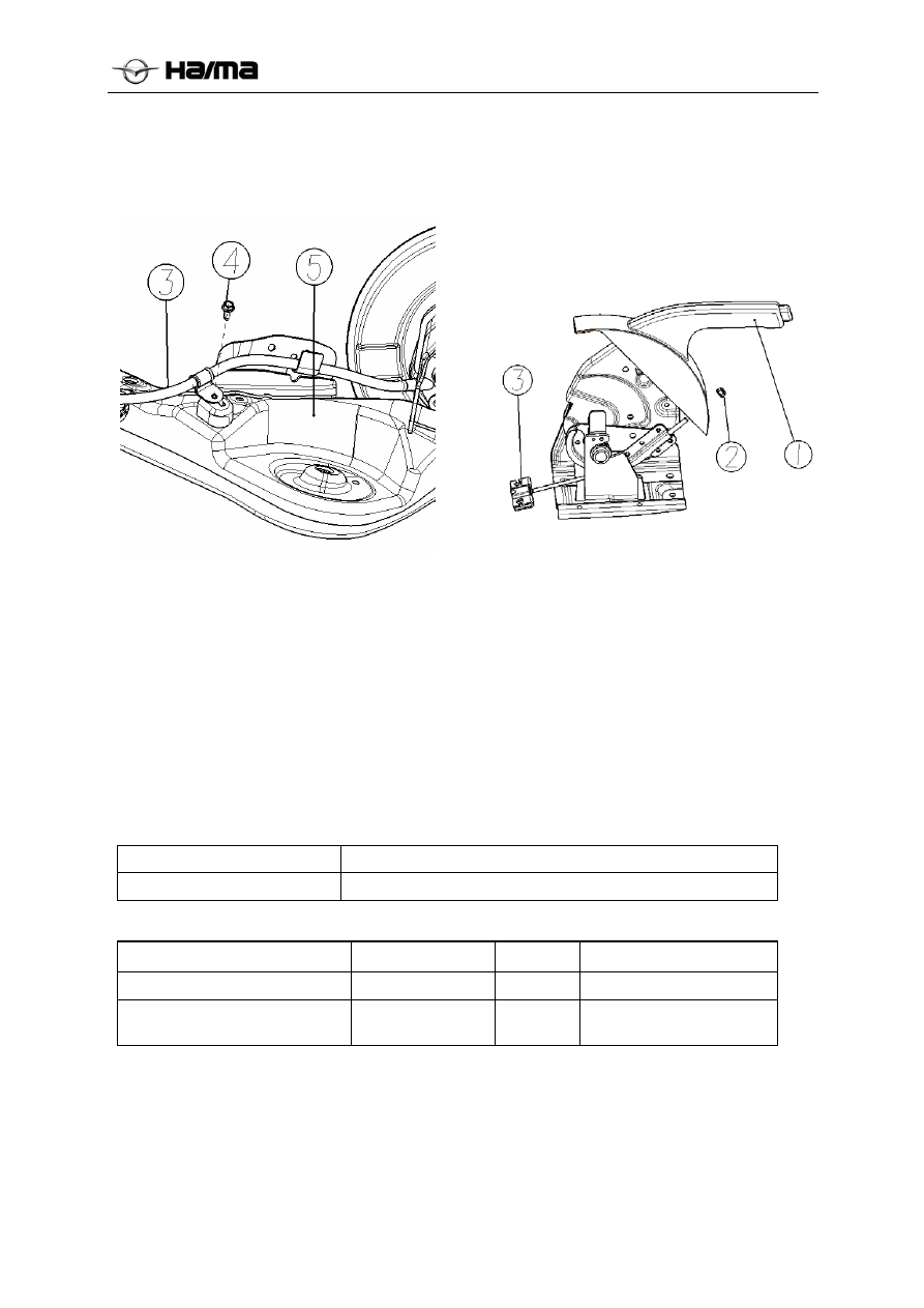
19N.m
3. Use the tool to remove the fastening bolts from
the rear bracket arm ④ ⑤
When mounting bolt tightening torque is: 18 ~
26N.m
Check of handle parking brake
1. Pull the parking brake handle several times.
2. Step the brake pedal several times.
3. Pull the parking brake handle with a force of
245N {25kgf, 55Ibf}, and check the stroke of
parking brake.
Stroke of 9-11 teeth.
Adjustment of parking brake handle stroke
1. Adjust the clearance of brake shoe.
2. Start the engine, and step the brake pedal
several times.
3. Stop
the
engine.
4. Turn the parking handle ① and ③ connect
cable assembly before adjusting nut ②, pull
the handle to test its stroke.
5. After adjusting it, check the following points:
(1) Turn the ignition switch, pull the parking
brake handle by 1 tooth, and confirm that the
parking brake lamp goes on.
(2) Confirm no brake drag of rear brake.
Parameters
General technical parameters
Item Instructions
Stroke of parking brake handle 9 to 11 teeth[tensile force of 245N (25 kgf, 55 Ibf)]
Locking torque parameters
Item Nm
Lb-Ft
Lb-in
Parking handle mounting nut
22
-
89
Parking cable fixed support
mounting bolt
17 -
69