Haima S5. Chassis System. Instruction - part 4


  Index      Haima     Haima S5. Chassis System. Instruction


Search            copyright infringement  


Content      ..     2      3      4      5     ..


Haima S5. Chassis System. Instruction - part 4


Steering system 2E-15 


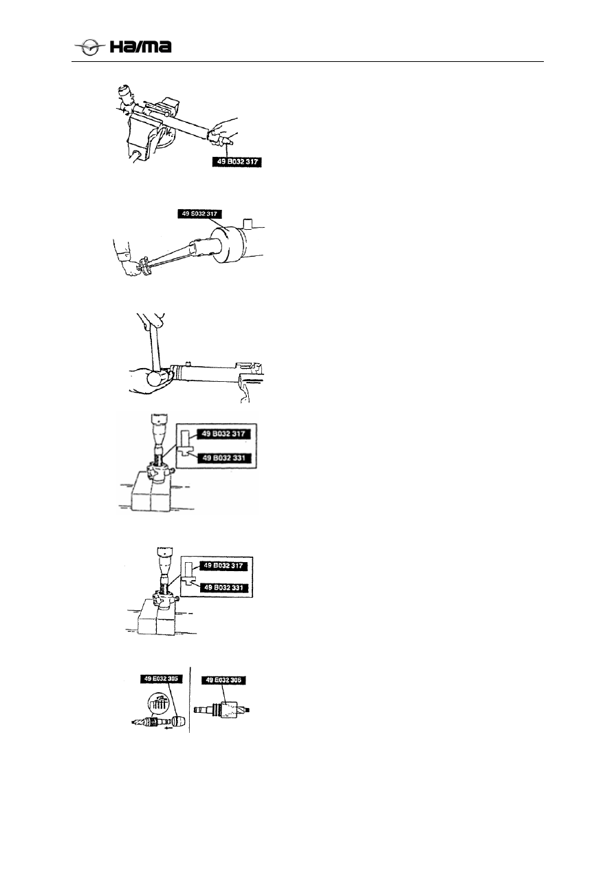
Keypoints for installing the hoop 

1.  Apply a little of lubricating oil to “O” ring and 

U seal gasket. 

2.  Install “O” ring and U seal gasket on the socket 

sleeve. 

3.  Install them on the steering gear with a special 

tool. 


4.  Install the hoop with a special tool. 


5.  Fix the hoop on cylinder body with a chisel. 


Keypoints for installing the oil seal 

1.  Apply the appropriate amount of grease to new 

oil seal. 

2.  Press in the new oil seal with a special tool. 


Keypoints for installing upper bearing 

1.  Apply the appropriate amount of grease to new 

upper bearing. 

2.  Press in the bearing with a special tool. 


1.  Attach a new seal ring to the valve body of 

gear shaft with a special tool. 

2.  After the installation, place the seal ring in 

position with a special tool. 

3.  Install the snap ring. 

-------------------------------------------------------------------------------------------------------------------------------------------------------------


Steering system 2E-16 


Keypoints for installing the adjusting cover 

1.  Place the rack in middle position. 

2.  Tighten the adjusting cover up to its tightening 

torque of 19.6N.m{2.0kgf.m} three times, and 
then turn the end cover by 23° with a special 
tool.  


[Reading of spring balance]9.9-13.7N{1.0-1.4kgf} 

Install the lock nut with a special tool.  

Tightening torque: 40-49N·m{4. 0-5.0kgf.m} 


Check of air tightness 

1.  Connect the special tool to the gear chamber 

booster cylinder. 

2.  Apply a vacuum pressure of 53.3kpa 

{400mmHg,15.7inHg) to cylinder with a 
vacuum pump, and ensure that its vacuum 
pressure can be kept for at least 30s. 

  If this vacuum pressure can’t be kept, replace 

the oil seal. 


-------------------------------------------------------------------------------------------------------------------------------------------------------------


Steering system 2E-17 


Removal and installation of power steering pump 

1.  Remove it in the sequence shown in the table. 

2.  Install it in the reverse sequence of removal. 

3.  Adjust the drive belt (refer to the drive belt, 

adjustment of drive belt). 


1 Adjusting 

bolt 

2 Tightening 

bolt 

3 Drive 

belt 

Pressure switch plug 

5 High-pressure 

pipe 

6 Oil 

suction 

hose 

Oil pump and support 


-------------------------------------------------------------------------------------------------------------------------------------------------------------


Steering system 2E-18 


Disassembly and assembly of power steering pump 

Note

  The following operation can be performed only after replacing “O”ring and oil seal. If it’s still 

required to check other items, replace the pump body assembly. 

1.  Disassemble it in the sequence shown in the table. 

2.  Assemble it in the reverse sequence of disassembly. 


Power steering pump assembly: refer to 
its disassembly instructions. 


Cam ring: refer to its installation 
instructions. 

2 Bolt 


10 Snap 

ring 

Oil suction pipe  


11 

Rotor 

4 O 

ring 


12 

Impeller: refer to its assembling 
instructions. 

Pressure switch 


13 

Front pump body 

Rear pump body: refer to its assembling 
instructions. 


14 Shaft 

assembly 

7 O 

ring 


15 

Oil seal: refer to its assembling 
instructions. 

8 Side 

disc 


-------------------------------------------------------------------------------------------------------------------------------------------------------------


Steering system 2E-19 


Keypoints for disassembling the power steering 
pump assembly 

Note

  While clamping the assembly with a vice, fix, 

remove and assemble it with a special tool to 
avoid the damages of oil pump.  


Keypoints for installing the oil seal 

Note

  Locate the pump body. Install the oil seal with 

a special tool and hammer. 


Keypoints for installing the blade 

Place the blade inside the rotor, the round edge of 
blade shall contact with that of inner cam ring. 


Keypoints for installing inner cam ring 

With the mark up, install the inner cam ring into 
front pump body. 


Keypoints for installing rear pump body 

After installing rear pump body, turn the wheel shaft 
by hands, and observe whether it rotates smoothly. 


-------------------------------------------------------------------------------------------------------------------------------------------------------------


Brake system 2F-1 


Chapter 15 

Brake system 


General and operation ............................................................................................................................ 2F-2 

Description of ABS fault light...................................................................................................... 2F-2 

Description of ESC fault light ...................................................................................................... 2F-2 

Description of ESC-OFF switch indicator lamp........................................................................... 2F-2 

Parts of brake system.............................................................................................................................. 2F-3


 brake system ...................................................................................................................................... 2F-3


 brake system2 ....................................................................................................................................... 2F-4


Diagnostic data and procedures .................................................................................................... 2F-5 

Faults of brake system .................................................................................................................. 2F-6 

Instruction exhaustion........................................................................................................................ 2F-6 

Check of pedal stroke ................................................................................................................... 2F-7 

Check of brake pedal free stroke .................................................................................................. 2F-7 

Repair instructions 1..................................................................................................................... 2F-8 

Specifications.............................................................................................................................. 2F-10 

Circuit diagram ............................................................................................................................2F-11 


Repair instructions 2........................................................................................................................ 2F-12 

Brake master cylinder with oil cup ............................................................................................. 2F-12 

Diagnostic references and procedures ........................................................................................ 2F-12 

Brake master cylinder with brake fluid reservoir assembly........................................................ 2F-12 

Specifications.............................................................................................................................. 2F-13 

Vacuum booster ................................................................................................................................ 2F-13 


Check of vacuum booster................................................................................................................. 2F-13 

Check of vacuum booster functions(simple methods).................................2F-错误!未定义书签。 

Check of vacuum booster functions (check them with a measuring instrument) ....................... 2F-17 

Vacuum hose assembly..................................................................................................................... 2F-14 

Vacuum hose assembly (1.6L engine)........................................................................................ 2F-14 

Vacuum hose assembly (1.5T engine).........................................................2F-错误!未定义书签。 

Electric vacuum pump

................................................................................................................ 2F-15 

Electric vacuum pump (1.5T engine only) ................................................................................. 2F-15


Front and rear brakes........................................................................................................................... 2F-17 

General and operation................................................................................................................. 2F-17 

front-disc brake........................................................................................................................... 2F-17 

Rear brake disc with drum brakes............................................................................................... 2F-25 

Parking brake system............................................................................................................................ 2F-25 

General and operation................................................................................................................. 2F-25 

-------------------------------------------------------------------------------------------------------------------------------------------------------------


Brake system 2F-2 


Structure diagram ....................................................................................................................... 2F-25 

Repair instructions...................................................................................................................... 2F-25 

ABS 9 system ......................................................................................................................................... 2F-27 

ABS 9 Overview..................................................................................................................................... 2F-27 

I. Attentions ................................................................................................................................ 2F-27 

II. Initial check............................................................................................................................ 2F-29 

Introduction of ABS 9 system .............................................................................................................. 2F-31 

I. Composition of ABS 9 system ................................................................................................ 2F-31 

II. Hydraulic diagram for Haima S5 ABS 9 X-type arrangement .............................................. 2F-31 

III. Haima S5 ABS 9 ECU interface circuit................................................................................ 2F-33 

ABS Fault diagnosis .............................................................................................................................. 2F-35 

I. Diagnostic flow ....................................................................................................................... 2F-35 

II. For the faults without fault codes, repair it. ........................................................................... 2F-36 

III. Repair of occasional faults.................................................................................................... 2F-36 

IV. Analysis of fault codes ......................................................................................................... 2F-37 

ABS removal and installation............................................................................................................... 2F-43 

I. Steps for removing ABS assembly.......................................................................................... 2F-43 

II. Installation steps of ABS assembly........................................................................................ 2F-43 

III. Cross validation .................................................................................................................... 2F-43 

IV. Exhaust instructions.............................................................................................................. 2F-43 

V. Repair technical parameters................................................................................................... 2F-43 

Summary ESC system......................................................................................................................... 2F-47 

I. Attentions ................................................................................................................................ 2F-47 

II. Initial check............................................................................................................................ 2F-48 

Introduction of ESC system ................................................................................................................. 2F-51 

I. Composition of ESC system.................................................................................................... 2F-51 

II. Hydraulic diagram for ESC.................................................................................................... 2F-51 

III.Haima S5 ESC ECU interface circuit .................................................................................... 2F-53 

Fault diagnosis ....................................................................................................................................... 2F-57 

I. Diagnostic flow ....................................................................................................................... 2F-57 

II. For the faults without fault codes, repair it. ........................................................................... 2F-58 

III. Repair of occasional faults.................................................................................................... 2F-58 

IV. Analysis of fault codes ......................................................................................................... 2F-59 

Removal and installation ...................................................................................................................... 2F-66 

I. Steps for removing ESC assembly .......................................................................................... 2F-66 

II. Installation steps of ESC assembly ........................................................................................ 2F-66 

III. Exhaust instructions.............................................................................................................. 2F-66 

 Instructions for calibrating the integrated inertial sensor (ESPC system) ..................................... 2F-68 

 Repair technical parameters....................................................................................................... 2F-69 

-------------------------------------------------------------------------------------------------------------------------------------------------------------


Brake system 2F-1 


-------------------------------------------------------------------------------------------------------------------------------------------------------------


Brake system 2F-2 


General and operation 

Operation of brake caution light  

The brake caution light (BRAKE)

 applied  in 

this brake system is located inside the instrument 
panel. When the ignition switch is in ON gear, the 
brake caution light will go on. When the ignition 
switch returns to ACC gear, the caution light will 
go out. The following cases will make the caution 
light go on. 

   In case of applying the parking brake when 

the ignition switch is in ON gear, the caution 
light will go on. 

  When the level of brake fluid is below a 

certain value, “BRAKE” 

 caution light will 

go on. 


Description of ABS fault light 

ABS fault light 

 applied in this brake system is 

located inside the instrument panel (as shown in 
the figure). 

Self-check of ABS: when the ignition switch is 
turned from ACC to ON, the self-check of ABS is 
started, and the fault light goes on. After finishing 
its self-check within 0.7 to 3s, the fault light goes 
out, it certifies the normality of ABS system; if it’s 
constantly on, ABS system will be faulty, and the 
professionals are required to check the faults of 
ABS system (for its details, see the description of 
ABS anti-lock system repair). 


Description of ESC fault light 

ESC fault light

 applied in this brake system 

is located inside the instrument panel (as shown in 
the figure). 

ESC self-check: when the ignition switch is turned 
from ACC to ON, the self-check of ESC is started, 
and the fault light goes on at this time. After 
finishing its self-check, the fault light goes out, and 
it certifies the normality of ESC system; if it’s 
constantly on, ESC system will be faulty, and the 
professionals are required to check the faults of 
ESC system (for its details, see the description of 
ESC anti-lock system repair). 


Description of ESC-OFF switch indicator 
lamp 

ESC instruction switch indicator lamp 

applied in 

this brake system is located inside the instrument 
panel (as shown in the figure). 

When ESC-OFF light

goes on, it indicates the 

functions of ESC is instructionly closed, its functions 
can be started with ESC switch button, and ESC-

OFF light

will go out after starting it. 


ESC snow mode lamp

 located  in  the 

instrument panel. When snow mode ESC


lighting, indicating the snow mode ESC mode is 
active

.


-------------------------------------------------------------------------------------------------------------------------------------------------------------


Brake system 2F-3 


Parts of brake system 

Brake system (I) 


1. Front steering knuckle 
with brake assembly(right) 

2. Front brake hose 
assembly(right) 

3. Washer 

4. Hollow bolt   

5. Front ABS wheel speed 
sensor  

6. Elastic card       

7. Pipe clamp   

8. Front brake hose assembly 
(left) 

9. Front steering knuckle 
with brake assembly(left)  

10. ASB control unit 

11. ABS support cushion  

12.  ABS support 

13.  Bolt  

14. Pipe clamp E 

22. Front brake pipe(right)  

23. Rear brake pipe front 
section (right) 

24.Brake master cylinder 
driven cavity oil pipe 
25. Brake master cylinder 
active cavity oil pipe  

26. Rear brake hose 
assembly Ⅰ 

27. Rear brake pipe rear 
section (right) 

28. Pipe clamp D 

29.Support- Rear brake hose 
(right) 

30. Rear brake hose 
assembly Ⅱ (right) 

31.Middle support-Rear 
wheel speed sensor 

32. Support- Rear brake hose 
(left) 

36. Rear brake pipe middle 
section (left) 

37. Rear brake pipe middle 
section (right) 

38. Pipe clamp   

39. Rear brake discs 

40. Flange  Bolt 

41.Rear ABS wheel speed 
sensor 

42. Flange  Bolt 

43. Flange bolt 

44.Rear axle hub unit 

45.Rear parking brake 
assembly (left/right) 

46.Bolt- Brake pedal  

47. Brake pedal assembly 

48.Support-  vacuum booster 

49. With master cylinder 
vacuum booster assembly 

54.

 Vacuum power-assisting 

hose assembly 

55. Bolt- Vacuum power-
assisting hose 

56.Front chamber brake hose

57. Rear chamber brake hose

58.Bolt - vacuum booster 
support 

59. Pin shaft 

60. Split pin 

61. Parking brake handle 
assembly 

62.Bolt- Parking brake 
handle 

63.Lock bolt- Front section 
cable 

64.Front section cable 

65. Rear parking cable 
assembly (right) 

Brake system(with ABS) 

-------------------------------------------------------------------------------------------------------------------------------------------------------------


Brake system 2F-4 


15. Pipe clamp  

16. support- Pipe clamp 

17. Flange  nut 

18. Pipe clamp  

19. Pipeline joints 

20. Front brake pipe(left)  

21. Rear brake pipe front 
section(left)


33. Rear brake hose 
assembly Ⅱ (left) 

34.Rear brake assembly 
(left/right) 

35. Rear brake pipe rear 
section (left) 


50. Elastic pipe clamp 
(vacuum hose) 

51.Fluid reservoir assembly 

52.Bolt- Fluid reservoir 

53. Elastic pipe clamp 
(front/rear chamber hose) 

66.Bolt- Rear parking cable 

67. Rear parking cable 
assembly (left) 


Brake system (II) 


1. Front steering knuckle 
with brake assembly(right) 

2. Front brake hose 
assembly(right) 

3. Front ESC wheel speed 
sensor 

4.  Elastic card    

5. Front steering knuckle 
with brake assembly(left) 

6. Hollow bolt   

7. Washer 

23. Front brake pipe(left)  

24. Rear brake pipe front 
section(right) 

25. Front brake pipe(right) 

26. Rear brake pipe front 
section(left) 

27. .Brake master cylinder 
driven cavity oil pipe 
28. Brake master cylinder 
active cavity oil pipe  

29. Rear brake hose 
assembly Ⅰ 

40. Rear brake discs 

41.Rear brake assembly (left)

42.Bolt 

43.Rear ESC wheel speed 
sensor 

44.Flange bolt 

45.Flange bolt 

46. Rear axle hub unit 

47.Rear parking brake 
assembly (left) 

59. Bracket- Electric vacuum 
pump  

60.Bolt- Electric vacuum pump 
bracket 

61. Electric vacuum pump  

62.Bolt- Electric vacuum pump 

63. Vacuum power-assisting 
hose (rear section) 

64.Bolt- Vacuum power-
assisting hose (rear section) 

65. Dual Slot pipe clamps Ⅰ 

Brake system(with ESC) 

-------------------------------------------------------------------------------------------------------------------------------------------------------------


Brake system 2F-5 


8.ESC hydraulic unit  

9.Steering angle sensor 

10.Support-ESC 

11.Bolt 

12.bolt 

13. ESC support cushion  

14. Pipe clamp  

15. Pipe clamp  

16 Pipe clamp G 

17.. Front brake hose 
assembly (left) 

18. Pipe clamp 

19. Pipe clamp 

20. Pipeline joints 

21.Support-Pipe clamp 

22.Flange nut  


30. Rear brake pipe rear 
section (right) 

31. Support- Rear brake 
hose (right) 

32. Rear brake hose 
assembly  

(right)


33. Rear brake pipe middle 
section (right) 

34. Pipe clamp D 

35. Middle support-Rear 
wheel speed sensor 

36. Support- Rear brake 
hose (left) 

37. Rear brake hose 
assembly (left)


38. Rear brake pipe rear 
section (left) 

39. Rear brake pipe middle 
section (left) 

48.Bolt- Brake pedal 

49. Brake pedal assembly 

50.Support-  vacuum booster

51. With master cylinder 
vacuum booster assembly 

52. Fluid reservoir assembly 

53. Bolt- Fluid reservoir 

54. Elastic pipe clamp 
(front/rear chamber hose) 

55. Rear chamber brake hose

56. Front chamber brake 
hose 

57. Vacuum power-assisting 
hose (front section) 

58.Bolt- Vacuum power-
assisting hose ( front 
section) 


66. Dual Slot pipe clamps Ⅱ 

67. Bolt - vacuum booster 
support 

68. Split pin 

69. Pin shaft 

70. Parking brake handle 
assembly 

71. Bolt- Parking brake handle 

72. Lock bolt- Front section 
cable 

73. Front section cable 

74. Rear parking cable 
assembly (right) 

75. Bolt- Rear parking cable 

76. Rear parking cable 
assembly (left) 


Diagnostic data and procedures 

Brake system test 

The brake test must be performed on dry, clean and 
flat road without slope. If the road surface is wet 
and slippy, oil dirty or soft, the vehicle can’t stick 
to the ground evenly, thus its real braking 
performance can’t be tested. 

The brake test shall be performed with lighter and 
heavier pedal-applying forces at different speeds, 
but the lock of brake and slippage of vehicle must 
be avoided. Even if the vehicle is braked with a 
large force, its lock and slippage can show its 
braking ability. During the rotation of wheel, its 
braking distance is less than the one while it’s 
locked, the friction force between the wheel and 
ground is also below the force of wheel while it’s 
slipped. The higher its deceleration speed is, the 
higher the required brake pedal force is. Three key 
external factors can influence its braking ability: 

  The uneven adhesion between the tire and 

ground will lead to uneven braking force, the 
air pressures of left and right tires shall be 
equal to each other, and the patterns of left 
and right tires shall be the same. 

  Uneven load will also influence its braking 

ability, because the wheel with higher load 
requires a higher braking input force than any 
other wheel, so it can also produce a higher 
braking force. 

  Projected or unflat road surface will cause the 

runout of brake. 

Check of brake fluid leakage: make the engine 
idling, put the gear in neutral gear, and step down 
the brake pedal with a consistent force. If the pedal 
sinks, the hydraulic system may be leaked, so the 
system shall be checked. 

Check of fluid level in master cylinder fluid 
reservoir: the slow drop of fluid in fluid reservoir 
is caused by normal wears of friction liner. 
However, its fluid level shows very low, it 
indicates the leakage of system. The system may 
be internally or externally leaked. Sometimes, if no 
faults of system are found out during the following 
check, it may be slightly leaked. If its fluid level is 
normal, check the length of vacuum booster 
pushrod. In case of finding out the improper length 
of pushrod, adjust or replace the pushrod. 

Check the master cylinder through the 
following procedures: 

  Check the casting cracks of master cylinder or 

leakage of brake fluid around it. If at least one 
drop of brake fluid exists outside the master 
cylinder, it indicates the leakage of master 
cylinder, but its problems can’t be explained 
only as per the wetting conditions of master 
cylinder.  

  Check the lengths of linkage and pushrod 

connected to the pedal. If these two parts 
don’t conform to the requirements, 
disassemble the master cylinder, and check 
whether the leather cup is extended or 

-------------------------------------------------------------------------------------------------------------------------------------------------------------


Brake system 2F-6 


expanded. If it’s expanded, the brake fluid 
may be unqualified or polluted. In case of 
confirming the pollution of brake fluid, all the 
parts shall be removed for cleaning, and all 
the brake pipes must be also cleaned.  

Unqualified brake fluid, other mineral oil or water 
in brake fluid will cause the gasification of brake 
fluid or deterioration of rubber parts,e.g. the 
expansion of master cylinder piston rubber cup 
indicates the deterioration of rubber part. 
Meanwhile, the same case also occurs to the brake 
slave cylinder rubber cup. 

In case of finding out the deterioration of rubber 
parts, disassemble all the hydraulic parts, and clean 
themwith alcohol; blow the alcohol dry with 

compressed air before reassembling them, and 
replace all the rubber parts from the system, 
including the hose. 

Check of brake hose 

The hydraulic brake hose shall be checked at least 
once every two years. After the occurrence of 
accidental damages, broken surface scratches, 
leakage or bubbles, the hose must be also checked. 
Check the trends and fixing conditions of hose. If 
the friction of brake hose with other parts occurs, it 
will lead to final failure of surface damages, and its 
check may require a mirror or light. If the above 
cases are found, the hose must be adjusted or 
replaced. 

Faults of brake system 

Fault symptom


Cause


Remedy


Leakage of brake fluid


Repair or add in the brake fluid.


Short circuit of parking brake 
switch


Repair its short circuit part.


The brake warning lamp is 

constantly on.


Fault of fluid level sensor


Replace the sensor.


Fault of brake lamp switch


Replace the brake lamp switch.


Too short length of pushrod


Adjust the length of vacuum 
booster pushrod.


The brake lamp goes on.


Short circuit of brake lamp switch


Repair its short-circuit part.


Lack or leakage of brake fluid


Repair or add in brake fluid.


Pollution of brake fluid


Replace the brake fluid.


Air in brake system


Drain the fluid out of brake 
system again.


Damages of brake pipe


Replace the brake pipe.


Insufficient braking force


Damages of vacuum power-
assisting hose or non-return valve


Replace the vacuum power-
assisting hose or non-return valve.

Seizure of brake pedal


Replace the brake pedal.


Fault of caliper piston return


Replace the return rubber ring.


Fault of brake master cylinder


Replace the brake master 
cylinder.


Braking drag


Air in brake system


Exhaust the air.


Insufficiency or leakage of brake 
fluid


Replace the leaked part or add in 
the brake fluid.


Overlong stroke of pedal


Overlong free stroke of brake pedal

Adjust the length of vacuum 
booster pushrod.


Manual exhaustion 

Important hints:  

the sequence of exhaustion:

 Whenever you have to 

disconnect the brake pipe exhaust brake system. If you 
disconnect the hydraulic lines in the brake master cylinder 

at the distance from the brake master cylinder brake sub-
cylinder exhaust farthest beginning, and then sub-divided 
cylinder brake far evacuated until 4 Cylinder complete until 
the completion of the exhaust; if off point is not the brake 
master cylinder at the break point distance from the nearest 
sub-cylinder began to exhaust brake, then the next nearest 
sub-cylinder, four cylinder until fully completed until the 

-------------------------------------------------------------------------------------------------------------------------------------------------------------


Brake system 2F-7 


exhaust.


During the drainage of fluid, check the level of 
fluid continually, and add in the brake fluid. 

1.  Lift up the vehicle. 

2.  Loosen the bleed bolt and dust cover. 


3.  Connect a transparent pipe to bleed screw, 

and make its other end soaked in the brake 
fluid of transparent container. 


4.  After stepping the brake pedal slowly several 

times, keep it stepped.  

5.  Loosen the bleed screw, drain the brake fluid, 

and then tighten the screw. 

Note:  Step the pedal until the bleed screw is 
tightened. 

6.  Repeat Steps 4 and 5 until all the air is bled. 

7.  Check whether the bleed screw is tightened. 

Note: 

a) The manual venting, while the exhaust side of 

the jar to check the brake fluid reservoir level, 
if less than the minimum tick, add brake fluid, 
after the completion of the exhaust, brake 
fluid is added to the specified value. 

b) must be dedicated hippocampus brake fluid 

DOT-4 brake fluid filling. 

Check of pedal stroke 

1.  Start the engine. 

2.  Step down the pedal three times. 

3.  Step down the brake pedal with about 15Kg 

(33Ibf) force, and measure the distance 
between the pedal and the lowest part of front 
barrier. 

Unit: mm


Parameter 50mm 


4.  If the distance is below 50mm, it may be 

caused by the worn size of rear brake shoe 
over its specified value or existence of air in 
the pipe. After replacing the brake shoe and 
bleeding all the air, if the distance is still 
below 50mm , it may be caused by the faults 
of rear brake shoe regulator or overlong 
stroke of vacuum booster pushrod, but this 
case seldom occurs. 

5.  After removing the brake drum, check the 

automatic clearance regulator. If it’s damaged, 
repair or replace it. 

Check of brake pedal free stroke 

1.  Step the brake pedal several times to 

eliminate the vacuum of vacuum booster. 

2.  Push the brake pedal by hands, and measure 

the stroke of pedal from its free state to 
hardening position. 

Unit: mm 

Specified value 

5-10 

3.  The free stroke of brake pedal can’t be 

adjusted. 


-------------------------------------------------------------------------------------------------------------------------------------------------------------


Brake system 2F-8 


Repair instructions 1 

(I)  Repair on the vehicle 

Front brake hose 

Procedures for removing: 

Note: 
Do not spill brake fluid or splashed paint. Brake 
fluid will damage the paint. If splashed paint on, 
then immediately wipe clean and washed with 
water. 

1.  Remove the wheel. 

2.  Remove the brake hose. 

  Loosen the connector ① connected to brake 

pipe. 

  Block the opening of brake pipe, and avoid 

the loss and pollution of brake fluid. 

  Remove the snap spring ②. 

  Loosen the connecting bolt ③. 

  Remove the brake hose from the support. 


Installation procedures: 

1.  Connect the brake hose to pipe ①. Tightening 

torque: 14 to 18N·m. 

2.  Install the snap spring ②. 

3.  Install the brake hose connecting bolt ③. 

Tightening torque: 22-29N·m. 

Important: please apply the brake fluid 
recommended by Sino Maersk Co., Ltd. 

4.  Exhaust the brake system. Refer to manual 

exhaustion in this chapter. 

5.  Confirm whether the brake system is leaked. 

6.  Install the wheel. 

Rear brake hose 

Removal procedures: 

  Remove the wheel, 

  Remove the brake hose. 

  Loosen the connector connected to brake pipe 

  Remove the snap spring ②. 

   loosen bolts ③.  

  Block the opening of brake pipe, and avoid 

the loss and pollution of brake fluid. 


Installation procedures: 

1.  Connect the brake hose to the pipe. 

Tightening torque: 14 to 18N·m (12 Ib-ft). 

2.  Install the snap spring. 

3.  Install the brake hose connecting bolt ③. 

Tightening torque: 22-29N·m. 

Important: please apply only the recommended 

brake fluid. 

4.  Exhaust the brake system. Refer to manual 

exhaustion in this chapter. 

5.  Confirm whether the brake system is leaked. 

6.  Install the wheel. 


Brake lamp switch 

Removal procedures: 

1.  Disconnect the negative cable of battery. 

2.  Remove the brake lamp switch. 

  Pull down the plug ①. 

-------------------------------------------------------------------------------------------------------------------------------------------------------------


Brake system 2F-9 


  Use a wrench to loosen the brake switch 

comes with the lock nut ②. 

   Rotating brake light switch, removed from 

the pedal. 


Installation procedures: 

1.  Install the brake lamp switch. 

        The  brake  pedal  switch  screwed  into  the 

switch bracket to the threaded end of the 
rotary switch to metal bracket rubber pad in 
contact with the pedal switch (no preload), the 
lock switch comes with a locking nut. 
Tightening torque 5-7N.m. 

2. Connect 

the 

plug. 

3.  Connect the negative cable of battery. 

4.     Detect brake lights are working properly. 


Important:  

Ensure the brake light switch on the brake 
pedal arm assembly after no preload. 

Brake pedal 

Removal procedures: 

1.  Remove the brake lamp switch. 

2.  Pull out the split pin  ,

 take down the pin 

shaft ,

 and disconnect the connection of 

vacuum booster and brake pedal. 

3.  Remove the bolt ③.Take down the pedal 

assembly. 


Assembling procedures: 

1. Use 

nut 

, the brake pedal is fixed to the 

vehicle body. 

2.  Use and cotter pin ②  ① connection with 

vacuum booster brake pedal. 

3.  Install the brake lamp switch. 


-------------------------------------------------------------------------------------------------------------------------------------------------------------


Content      ..     2      3      4      5     ..