Haima S5. Chassis System. Instruction - part 5
Brake system 2F-10
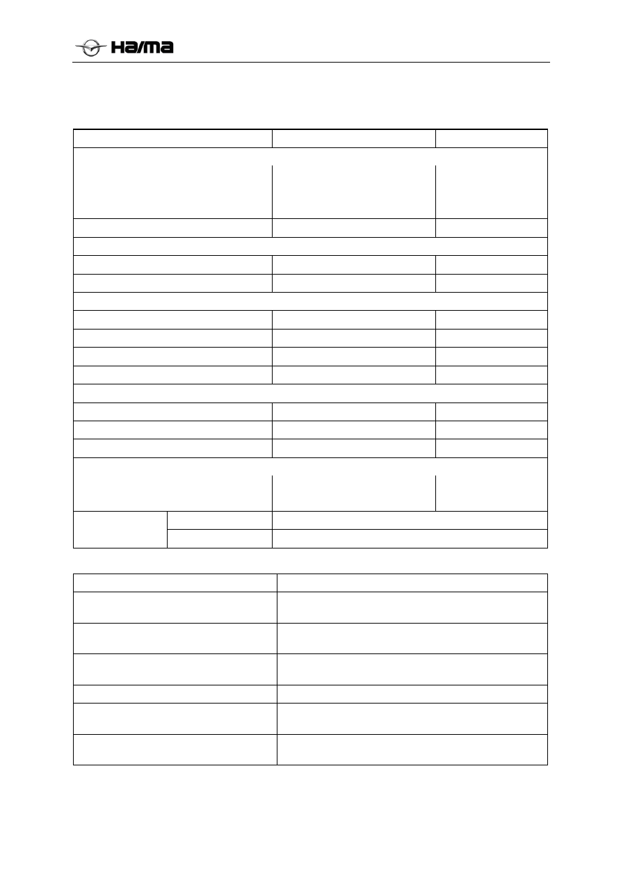
Specifications
General parameters
Item mm
Front brake
Diameter of brake disc
Thickness of brake disc
Valid thickness of disc
φ296
26
24
Diameter of caliper cylinder
Φ60.3
Rear-drum brake
Specification
Φ172×20
Inner diameter of brake drum
Φ172
Rear-disc brake
Diameter of brake disc
φ292
Thickness of brake disc
9
Valid thickness of disc
7
caliper cylinder diameter
φ35
Vacuum booster with brake master cylinder assembly
Assist rate
9
diameter of master cylinder
23.8
Stroke of master cylinder
18+18
Brake pedal
free stroke
Valid stroke
6-10
120
Type DOT-4
brake fluid
Capacity 700ml±50ml
Tightening torque specifications of fasteners
Application
N·m
Install the brake oil pipe at the joint of
brake oil pipe.
14 to 18
Mounting bolt of front brake hose and
caliper
22 to 29
Connecting bolt of brake pedal and pedal
support
19 to 25
brake hose support tightening bolt
8 to 14
Connecting bolt of wheel speed sensor
support
8 to 14
ABS/ESP/proportional valve support
mounting bolt
20 to 24