Haima S5. Chassis System. Instruction - part 3


  Index      Haima     Haima S5. Chassis System. Instruction


Search            copyright infringement  


Content      ..     1      2      3      4      ..


Haima S5. Chassis System. Instruction - part 3


Suspension system 2D-4 


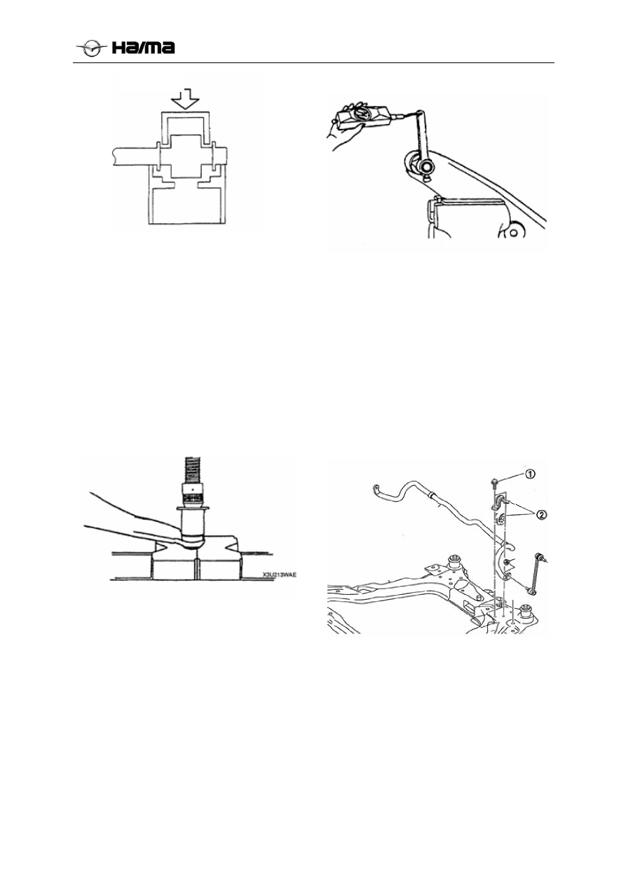
Keypoints for installing the lower swing front 
bush 

1. Place the alignment mark on the demolition 
done, make sure the angle of the bushing press-
fitting the body correctly. 

2. Press a new bush into swing arm body with SST  
special service tool. 

Keypoints for installing the dust cover 

1.  Wipe off the grease from the ball head bolt. 

2.  Fill the grease into the new dust cover. 

3.  Press the dust cover on the ball joint with SST 

special service tool. 

4.  Wipe off the excessive grease. 


Check of front lower swing arm 

1.  Remove lower swing arm from the vehicle. 

2.  Check it for damages, cracks and bends. 

3.  Check the rotation torque of ball joint. 

(1)  Turn the ball joint five times. 

(2)  Connect SST special service tool to ball head 

bolt, and measure its rotation torque with a 
tension meter. If unqualified, replace the 
lower swing arm. 

Pre-load of ball joint: 1.0 -4.9N.m {0.1-0.5kgf.cm, 
0.74-3.6in.lbf} 

Reading of tension meter: 10-49N {1-5kgf, 0.225-

1.1lbf} 


Removal/installation of front transverse 
stabilizer bar 

1.  Remove the front suspension crossbeam 

assembly (refer to the removal/installation of 
R-9 front suspension crossbeam assembly). 

2.  Remove the control front stabilizer bar 

connecting rod assembly and coupling nut ①. 

3.  Remove the front stabilizer bar fixing plate 

nut, front stabilizer bar fixing plate, stabilizer 
bar rubber bushings, stabilizer bar rubber seat 

4.  Install it in the reverse sequence of removal. 


Keypoints for installing front transverse 
stabilizer bar fixing plate 

1.  Apply the rubber grease to inner surface of 

stabilizer bar rubber sleeve. 

2.  When installing rubber sleeve, insert the 

rubber sleeve notch toward the vehicle rear 
stabilizer bar fixing plate of the hole toward 
the rear of the car. 

3.  Before installing the stabilizer bar fixing plate. 

Press in


-------------------------------------------------------------------------------------------------------------------------------------------------------------


Suspension system 2D-5 


Removal/installation of front suspension 
crossbeam assembly 

1.  Remove the rubber lug of exhaust pipe (refer 

to removal/installation of F exhaust system). 

2.  Remove the engine mounting suspension 

(refer to the keypoints for removing B engine 
support beam). 

3.  Remove the steering gear and tie rod(refer to 

removal/installation of N steering gear and tie 
rod). 

4.  Remove the front suspension lower swing 

arm assembly(refer to removal/installation of 
R-6 front suspension lower swing arm 
assembly). 

5.  Remove front transverse stabilizer bar(Refer 

to removal/installation of R-8 front transverse 
stabilizer bar). 

6.  Remove the front suspension cross member 

and the body mounting bolts ①, 
Remove the front suspension cross member 
assembly and body mounting bolts ② and ③. 

7.  Install the assembly in the reverse sequence of 

removal. 

8.  Check the location of front wheel, and adjust 

its location if necessary. 


Keypoints for removing the front suspension 
crossbeam assembly 

1.  Support the front suspension crossbeam 

assembly with a jack, and remove the bolts 
connected to vehicle body. 

Bolt torque: 90-100N.m  

2.  Remove the front suspension crossbeam 

assembly. 

Rear suspension  

Removal/installation of rear shock 
absorber and spring 

Note

In case of not removing ABS anti-lock brake 
system wheel speed sensor first, carry out the 
following operation procedures. If the sensor is 
inadvertently pulled, it may cause the broken 
circuit of wire. Before carrying out the following 
operation procedures, remove ABS wheel speed 
sensor from axle side, and fix it in appropriate 
position to prevent the sensor from inadvertent 
pulling during the repair of vehicle. During the use 
of jack, be sure to avoid the damages of brake pipe 
and brake hose. 

1.  In accordance with the order shown in the 

table (see the front suspension disassembly 
sequence table) Remove the stabilizer bar and 
the rear connecting rod; 

2.  Withstood the shock absorbers and the rear 

trailing arm with the Department, so that the 
shock absorber in a slightly compressed state, 
removed the damper and trailing arm 
connection fasteners. 

3.   Remove the shock absorber and rear sub-frame 

-------------------------------------------------------------------------------------------------------------------------------------------------------------


Suspension system 2D-6 


connection fasteners. 

4. In accordance with the reverse order of removal 

to install.. 


Check of rear shock absorber 

Check rear shock absorber by adopting the same 
method as that of front shock absorber (refer to the 
check of R-6 front shock absorber). 

Scrapping of rear shock absorber 

Handle rear shock absorber by adopting the same 
method as that of front shock absorber (refer to the 
scrapping of R-6 front shock absorber). 

Removal/installation of rear spiral spring 

1. Remove rear shock absorber assembly. 

2. Remove the trailing arm connected with the 

trailing arm mount fasteners. 

3. Dropped out after trailing arm coil springs 

4. In accordance with the reverse order of removal 

to install. 

Installation of rear spiral spring 

Installation of coil springs, coil springs ensure 
lower after opening rubber seat is always in a 
compressed state. 

Warning 

It’s very dangerous to install the spiral spring, 
because the spiral spring may fly off and lead to 
serious injury or death. 

Removal/installation of Rear suspension 
and subframe overall 

1.  Lift the vehicle to its appropriate position, and 

remove the tire. 

2. Disconnect the brake lines, parking and a variety 

of cable harness connector. 

3. Remove the trailing arm connected with the 

trailing arm mount fasteners. 

4. Remove the coil spring. 

5. After the top high jacking device subframe 

assembly. 

6. Remove the subframe and body connection bolts. 

7. Removing the order shown in the table. 

8. Install the reverse order of removal order. 


-------------------------------------------------------------------------------------------------------------------------------------------------------------


Steering system 2E-1 


Chapter 14 

Steering system


General procedures ................................................................................................................................. 2E-2 

Attentions for steering system ...................................................................................................... 2E-2 

Removal/installation of power steering assembly ........................................................................ 2E-2 

Disconnection and connection of joint ......................................................................................... 2E-2


Leakage check of power steering oil ............................................................................................ 2E-2


Check of power steering hydraulic force...................................................................................... 2E-2


steering wheel and steering column ....................................................................................................... 2E-3 

Check of steering wheel and steering column .............................................................................. 2E-3 

Check of steering wheel clearance................................................................................................ 2E-3 

Check of steering wheel loosening ............................................................................................... 2E-3


Removal and installation of steering wheel and steering column................................................. 2E-4


Keypoints for removing the steering wheel.................................................................................. 2E-5


Keypoints for removal of steering lock bolt and support ............................................................. 2E-5


Keypoints for removing the steering column external assembly.................................................. 2E-6


Keypoints for installing the steering lock bolt and support .......................................................... 2E-6


Keypoints for installing the steering shaft .................................................................................... 2E-6


Check of steering shaft ................................................................................................................. 2E-6


Removal and installation of steering gear and connecting rod ..................................................... 2E-7


Keypoints for removing and installing the bolt (telescopic shaft) ................................................ 2E-8


Keypoints for removing the Steering tie rod tail end ball head .................................................... 2E-8


Keypoints for removing the steering gear and joint...................................................................... 2E-8


Disassembly of steering gear and connecting rod......................................................................... 2E-9


Assembling of steering gear and connecting rod........................................................................ 2E-11


Removal and installation of power steering pump ........................................................................ 2E-16


Disassembly and assembly of power steering pump ...................................................................... 2E-17


Keypoints for disassembling the power steering pump assembly .............................................. 2E-18 

Keypoints for installing the oil seal ............................................................................................ 2E-18 

Keypoints for installing the blade............................................................................................... 2E-18 

Keypoints for installing inner cam ring ...................................................................................... 2E-18 

Keypoints for installing rear pump body .................................................................................... 2E-18 


-------------------------------------------------------------------------------------------------------------------------------------------------------------


Steering system 2E-2 


General procedures 

Attentions for steering system 

For removal/installation of wheel and tire 

The installation steps of wheel and tire are not 
described in this chapter. 

After removing the wheel, its tightening torque 
during the reinstallation: 110N.m(100 to 120 N.m). 

Removal/installation of power steering 
assembly 

If the power steering oil pipe is broken during the 
operation, add in some 

ATF-III or DEXRON-

III power steering oil after completing the 
operation

. Bleed the air out of power steering 

pipe, and check it for leakage. 

Disconnection and connection of joint 

Before any work to contact the plug by hands, 
disconnect the negative cable of battery. The cable 
can be reconnected only after finishing the work. 

Engine speed sensing power 
steering 

Exhaustion of air 

1.  Check the level of power steering oil(refer to 

the check of power steering oil, and check of 
liquid level). 

2.  Jack up the front end of vehicle with a jack, 

and support it with a safety support. 

3.  Turn the steering wheel to left or right 

furthest several times at the shutdown state of 
engine. 

4.  Check the level of power steering oil again. If 

its level is reduced, refill the power steering 
oil. 

5.  Repeat Steps 3-4 until the liquid level 

stabilizes at the specified value. 

6.  Lay down the vehicle. 

7.  Start the engine, and keep it idling. 

8.  Turn the steering wheel to left or right 

furthest several times. 

9.  Confirm that the power steering oil shall have 

no bubbles and its level shall not be reduced 
any longer. 

  If its level has been reduced, add in the power 

steering oil as per the demands, and repeat 

Steps 8 and 9. Check of power steering 
oil,Check of oil level,Check the level of 
power steering oil.If necessary, add in the 
power steering oil up to the specified level.  

The model of such power steering oil is 

ATF-III or DEXRON-III. 

Leakage check of power steering oil 

Note

  In case of keeping the steering wheel in the 

extreme steering position for over 5s, the 
temperature of power steering oil will be 
increased to an extreme value, and produce 
adverse influences on the power steering 
pump.  

1.  Start the engine, and idle it. 


 Note: 

  The parts shown with the arrows of figure 

may be leaked.  

2.  Turn the steering wheel to left or right 

furthest several times to make the oil pressure 
produced in every position. 

3.     Check them for leakage. 

Check of power steering hydraulic force


1.  Install the special tool as shown in the figure. 


2. Disconnect the high-pressure pipe from the oil 

pump, and connect to its special tool. 

-------------------------------------------------------------------------------------------------------------------------------------------------------------


Steering system 2E-3 


Tightening torque:45-55N·m{4.5-5.5kgf.m} 

3. Bleed the air out of the system. 

4. Fully open the valve of pressure gauge. 

5. Start the engine, and turn the steering wheel to 
left or right furthest to make the temperature of 
power steering oil up to 50-60°C{122-140°F}. 

Note: 

If the valve is closed for over 5s, the temperature 
of power steering oil will be increased to an 
extreme value, and produce adverse influences on 
the power steering pump. 

6. Fully close the valve of pressure gauge. 


7. Increase the engine speed up to 1000-1500rpm, 

and measure the pressure of power steering oil. 

If the hydraulic pressure is not within the 
specified range, it’s required to repair or replace 
the power steering pump assembly. 

Hydraulic pressure of power steering oil pump: 

7.7-8.4Mpa{78.0-85.0kgf/cm

2

,1116-1218psi} 

Note

In case of keeping the steering wheel in the 
extreme steering position for over 5s, the 
temperature of power steering oil will be 
increased to an extreme value, and produce 
adverse influences on the power steering pump. 

8. Fully open the valve of pressure gauge, and 

increase the engine speed up to 1,000-
1,500rpm. 


9.  Turn the steering wheel to left or right 

furthest, and then measure the hydraulic 
pressure produced in the gear chamber. 

Note

If the pressure is not within the specified 
range, it’s required to repair or replace the 
steering gear assembly. 

Hydraulic pressure in gear chamber (pump 
chamber): 

7.7-8.4Mpa{78.0-85.0kgf/cm

2

,1116-1218psi} 

10.  Remove the special tool. 

11.  Install and tighten the high-pressure pipe, and 

tighten it up to the specified torque. 

Tightening torque: 

45-55N.m{4,5-5. 5kgf.m} 

12.   Bleed the air out of system. 

Check of steering wheel and steering 
column 

Check of steering wheel clearance 

Stop the wheel directly in front, turn the steering 
wheel lightly to left or right, and confirm whether 
its oscillation amplitude is within the specified 
range. 

Note

If the clearance is not within the specified range, 
it may be caused by wears of steering knuckle or 
excessive clearance of steering gear, and apply 
the necessary corrections to it. Clearance: 0-
30mm{0-1. 18in} 

Check of steering wheel loosening 

Shake the steering wheel in the shown direction, 

Thermometer


Pressure gauge 

Valve fully closed

Valve iron


Thermometer

Pressure gauge 

Valve fully open 

-------------------------------------------------------------------------------------------------------------------------------------------------------------


Steering system 2E-4 


check the steering column bearing sleeve, steering 
shaft hinge for oscillation, steering wheel for 
loosening or steering column for loosening, etc. 


Check of steering wheel steering force 

1.  Check the following items. 

• 

Tire size and tire pressure. 

• 

Level of power steering oil. 

• 

Slack of drive belt. 

2.  Stop the wheel on firm or level road surface, 

and make the wheel directly in front. 

3.  Start the engine, and increase the temperature 

of power steering oil up to 50-60°C{122-
140°F}. 

4.  Remove the safety airbag module. 

Warning: 

  For removal/installation of safety airbag 

module after the check, refer to 
removal/installation of T safety airbag module 
on driver’s side. 

5.  Measure the steering force F with a torque 

wrench. 

  If not within the specified range, pay attention 

to the following items: 

 Existence of air in the system 

 Hose or joint for leakage 

 The performances of power steering pump 

and gear are perfect. 


Steering force: 7.8N·m{78kgf }.cm. 

Note

● 

In order to judge the conformity of results, 
check the steering operation of another 
vehicle with the same model with the same 
method under the same conditions, and 
compare the test results. 

● 

The rotation torque of steering wheel varies 
under the different conditions, as said below: 

 Road conditions, e.g. dry or wet road 

surface, asphalt or cement road surface. 

 Tire conditions, e.g. tire patterns, wears, 

tire pressure, etc. 

Removal and installation of steering 
wheel and steering column 

Warning

  Incorrect handling of safety airbag module 

will make the safety airbag suddenly opened, 
and it may cause the personal injury, so it’s 
required to handle the safety airbag. Please 
first read “Warning for Safety Airbag” (refer 
to the repair warning for safety airbag system.) 

1.  Remove them in the sequence shown in the 

table. 

2.  Install them in the reverse sequence of 

removal. 


-------------------------------------------------------------------------------------------------------------------------------------------------------------


Steering system 2E-1 


1


Safety airbag: refer to removal/installation of safety airbag system,T dirver’s safety 
airbag;


2


Lock nut


3


Steering wheel: refer to its removal instructions; refer to its installation instructions.


4


Steering column cover


5


Clock spring


6


Combination switch


7


Lower cover plate


8


Steering column: refer to its installation instructions.


9


Steering column lock sleeve


10


Steering column mount


11


Removed assembly of steering column: refer to its removal instructions.


Keypoints for removing the steering wheel 

Note

  Don’t hit the steering shaft with a hammer while 

removing the steering wheel, thus it will cause 
the collapse of steering column. 

1.  Make the wheel directly in front, and stop the 

vehicle. 

2.  Remove the steering wheel with an appropriate 

puller. 

Keypoints for removal of steering lock 
bolt and support 

1.  Make a groove in the lock bolt with a 

hammer and chisel. 

2.  Remove the bolt with a straight screwdriver. 

3.  Disassemble the steering lock assembly. 


-------------------------------------------------------------------------------------------------------------------------------------------------------------


Steering system 2E-7 


Keypoints for removing the steering 
column external assembly 

Note

  During the replacement of its external 

assembly, its coil must be replaced. 

1.  Turn the ignition key to “ACC” position. 

2.  Press down the lock button, and pull out the 

steering column external assembly. 


Keypoints for installing the steering lock 
bolt and support 

1.  Install the steering lock assembly on the 

steering shaft. 

2.  Confirm the correct locking operation. 

3.  Install the steering lock bolt. 

4.  Tighten the bolt until its head falls off. 


Keypoints for installing the steering shaft

Note

  Don’t shake the steering shaft in axial 

direction. 

1.  Tighten the bolt A. 

2.  After tightening the bolt B, tighten the bolt 

C. 


Check of steering shaft 

1.  Check the following items, and replace the 

steering shaft assembly if necessary: 

 Steering column bearing for damages. 

 Length of steering shaft. 

Length: 890.0-900.0 mm


2. Inclination 

operation 

  Confirm that the adjusting lever can move 

stably from its unlocked position to locked 
position. 

  Confirm that the steering shaft isn’t loosened 

when the adjusting lever is locked. 


Lock


Adjusting lever


Unlock

-------------------------------------------------------------------------------------------------------------------------------------------------------------


Steering system 2E-8 


Removal and installation of steering gear 
and connecting rod 

Note

  In case of not removing the wheel speed 

sensor from ABS system, carry out the 
following operation. When the wire is 
wrongly pulled, it may cause the broken 
circuit of wire. Before carrying out the 
following operation procedures, remove 
wheel speed sensor (from axle side), and 
place it in appropriate position to prevent it 

from wrong pulling during the repair of 
vehicle.  

1.  Remove front exhaust pipe fixing rubber 

sleeve. (refer to the exhaust system, 
removal/installation of exhaust system). 

2.  Remove it in the sequence shown in the table. 

3.  Install it in the reverse sequence of removal. 

4.  After installing it, check the toe-in of wheel 

(refer to the location of wheel, location of 
front wheel). 


1 Bolt 

2 Flange 

nut 

3 Flange 

nut 


-------------------------------------------------------------------------------------------------------------------------------------------------------------


Steering system 2E-9 


Keypoints for removing the bolt (telescopic shaft)

Make the aligning marks of gear shaft and gear 
chamber for the purpose of correct installation. 


Keypoints for installing the bolt (telescopic shaft)

After aligning the marks, install the intermediate 
shaft and bolt. 


Keypoints for removing the Steering tie rod tail 
end ball head 

1.  Remove the end rod nut. 

2.  Remove the end post from steering knuckle 

with a special tool. 


Keypoints for removing the steering gear and 
joint 

Draw the steering gear and joint out of right side. 


-------------------------------------------------------------------------------------------------------------------------------------------------------------


Steering system 2E-10 


Disassembly of steering gear and connecting rod 

1.  Disassemble it in the sequence shown in the table. 


1 Bolt 


12

End plugs and self-locking nuts


2 Heat 

shield 


13

Locknut - compact plug and plug the 
compact pieces together 

Oil pipe 1(long) 


14

Helical spring


Oil pipe 2(short) 


15

Support compact assembl

y


Outer ball end assembly


 16

Dust cover


Adjusting nut


 17

C-type snap ring


Small Clamps


 18

Seal - the upper valve


Tie Rod Dust


 19

Gear and valve assembly


Large Clamps


 20

Rack bushing assembly


10 

Tie Rod Assembly


 21

Seal - rack bushing


11 

Snap ring - rack stopper 

 22

Rack assembly


Keypoints for disassembling the insulation 
board 
 
1. Remove the bolts 
2. Remove the insulation board 

Keypoints for disassembling the outer ball joint 

assembly 
1. Loosen the adjusting nut 
2. Remove the outer ball joint assembly 

Keypoints for disassembling the tie Rod 
Assembly  
1. Remove the large and small clamps 
2. Remove the tie rod jacket 
3. Remove the tie rod assembly


Keypoints for disassembling the rack assembly  
1. Remove the snap ring - rack stopper 
2. Remove the rack bushing assembly 
3. Remove the piston - rack bushing 
4. Remove the rack assembly 

Keypoints for disassembling the gear and valve 
assembly  
1. Remove the self-locking nut and end plugs 
2. Remove the clamp plugs, coil springs and a 
compact plug 
3. Remove the dust cover and seal - the upper 
valve 
4. Remove the gear and valve assembly 


-------------------------------------------------------------------------------------------------------------------------------------------------------------


Steering system 2E-11 


Check of steering gear and connecting rod 

Check of rack 

1.  Check the rack for fracture, damages or broken 

teeth, etc. 

  If any, replace the rack. 

2.  Measure the radial runout of rack. If not within 

the specified range, replace the rack. Radial 
runout 

Near to A point: 0.15mm{0.006 in} 

Near to B point: 0.20mm{0.008 in} 


Check of steering tie rod end 

1.  Check the tie rod end for damages or rubber 

sleeve for cracks. 

2.  Replace if necessary. 

3.  Check the ball joint for loosening. 

4.  Replace the tie rod end if necessary. 

5.  Turn the ball head five times. 

6.  Measure the rotation torque of ball head with a 

special tool and spring. 

• 

If not within the specified range, replace the tie 
rod end. Rotation torque: 

0. 4-2.7N.m{3.5-26.0kgf.cm, 3.1-22.5in.lbf} 

Reading of spring balance: 

3. 4-25.5N{0.35-2.60kgf, 0.8-5.71bf} 


Check of steering tie rod 

1.  Check the tie rod for bends or damages, and 

replace it if necessary. 

2.  Check the ball joint for loosening, and replace 

it if necessary. 

3.  Swing the tie rod back and forth five times. 

4.  Measure the swing torque with a spring 

balance. 

If the torque is not within the specified range, 
replace the tie rod.  

Swing torque: 

0. 1-4. 0N·m(1-39kgf.cm, 0. 9-30. 8in.lbf} 

Reading of spring balance: 

0. 6-24. 5N.m{0. 06-2. 50kgf, 0. 13-5. 501bf} 


-------------------------------------------------------------------------------------------------------------------------------------------------------------


Steering system 2E-12 


Assembling of steering gear and connecting rod 

1.  Assemble them in the sequence shown in the table. 


Rack assembly


12 

Oil pipe 2(short) 

Gear and valve assembly


13 

Oil pipe 1(long)


Seal - rack bushing


 14 

Tie Rod Assembly


Rack bushing assembly


 15 

Adjusting nut


Snap ring - rack stopper  


 16 

Outer ball end assembly


Seal - the upper valve  


 17 

Tie Rod Dust


C-type snap ring


 18 

Large Clamps


End plugs and self-locking nuts   


 19 

Small Clamps 


Support compact assembl

y


20 

 Heat shield 

10 

Helical spring  


 21 


Bolt 

11 

Locknut - compact plug and plug the 
compact pieces together 

 22 

Dust cover


Installation of  gear and valve assembly 

1. Place rack assembly mounted within the housing 
assembly. 
2. In the case where the guaranteed centering of the 
rack gear and the valve assembly mounted within 
the housing assembly.  


Installation of  snap ring - rack stopper 

1. Place the seal - rack bushings and bushing 

assembly rack has a rack mount assembly. 

2. Insert the card ring - rack stopper into the disease 

cards in housing assembly snap ring grooves. 

-------------------------------------------------------------------------------------------------------------------------------------------------------------


Steering system 2E-13 


Installation of  end plug  

1. Install a good seal - the upper valve ring with C-
card limit. 
2. The self-locking nut installed. 
3. Replace the upper end plug and tighten. 

Installation of  briquetting plug 

1. Place the support clamp assembly alignment rack 

installed. 

2. Load coil spring. 

3. Replace the plug and lock nut clamps - compact 

plug. 

Installation of long and short oil pipe 

1.  The long and short tubing installed and locked. 

Installation of tie rod dust


1. Place the tie rod assembly installed. 
2. Place the tie rod retaining good suit with large  
and small clamps fixed. 

Installation of  outer ball end assembly


1. The adjustment nut is attached to the tie rod 

assembly. 

2. Place the outer ball head assembly installed. 

Installation of  insulation panels assembly 

1. The Insulation panels with fixing nut installed. 


Keypoints for installing the tie rod end rubber 
sleeve 

1.  Wipe off the oil dirt from the ball joint. 

2.  Put a little of grease into new dust jacket. 

3.  Install the dust jacket on the end of tie rod with 

a special tool and press. 

4. 

Wipe off all the exposed grease. 


Keypoints for installing the supporting rubber 
block 

1.  Apply the soap water to the rubber of 

supporting block. 

2.  Press the rubber support block with a special 

tool and press, until the rubber end comes out 
of gear chamber. 

-------------------------------------------------------------------------------------------------------------------------------------------------------------


Steering system 2E-14 


3.  Turn back the gear chamber, and press the 

rubber supporting block, until the rubber block 
comes out of its other side. 

4.  Align the rubber supporting block to steel pipe.


Attentions for installing the oil seal and bush 

1.  Install a new “O” ring and seal ring on the rack 

lever. 

2.  After installing the seal ring, make it tightly 

affix the lever. 

3.  Attach a new oil seal to (49B032 325) with a 

special tool (49 B032 324). 


4.  Remove the special tool (49B032325). 

5.  Place the oil seal on the edge of rack lever with 

a special tool, and remove the special tool. 

6.  Attach a new bush to steering rack.  

Note

  While pressing it in, the applied force shall not 

exceed 39kpa{400kg}cm2, 5688psi} to avoid 
the damages of oil seal and bush. 

  Apply a little of grease to the seal ring and oil 

seal bush. 


7.  Install the steering rack into gearbox, and press 

in the oil seal and bush with a special tool, until 
it’s difficult to press. 

Oil seal 

Rubber mat

Steel pipe

The rubber block end is 
aligned to steel pipe.

-------------------------------------------------------------------------------------------------------------------------------------------------------------


Content      ..     1      2      3      4      ..