Haima S5. Chassis System. Instruction - part 7


  Index      Haima     Haima S5. Chassis System. Instruction


Search            copyright infringement  


Content      ..     5      6      7      8     ..


Haima S5. Chassis System. Instruction - part 7


Brake system 2F-42 


1)  For the faults of wheel speed sensor signals, after removing the faults, be sure to start the vehicle and 

increase its speed up to about 15km/h, thus ABS warning lamp can go out. 

2)  Don’t measure the supply voltage from the wheel speed sensor to ECU. Once the open circuit of 

wheel speed sensor exists, ECU will stop its power supply automatically, until its power supply is 
recovered after the next ignition self-check.  
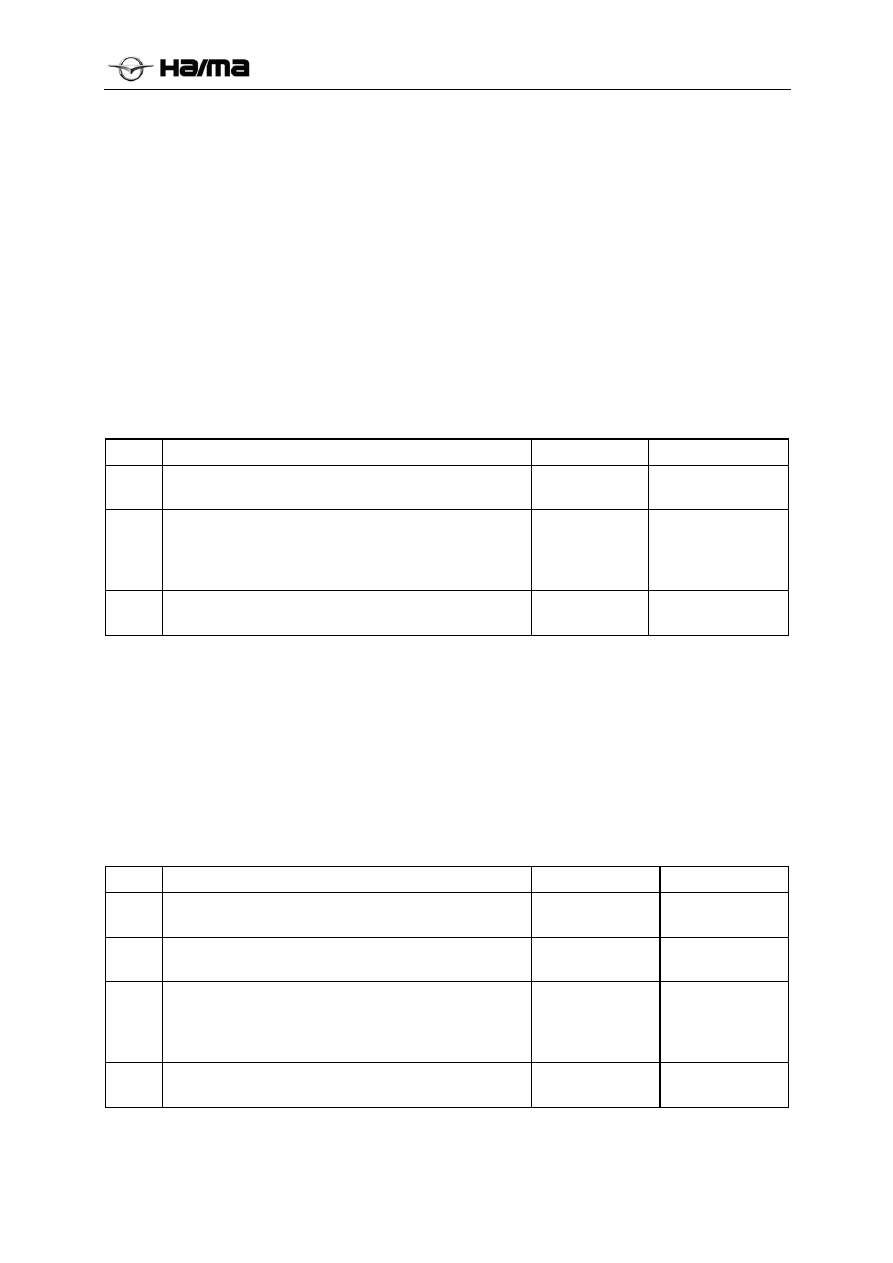
4.7 ECU faults 

Fault codes: C100004; C101008 

Fault setting conditions 

(1)  ECU supply fault.  

(2)  Damages of ECU. 

Possible fault causes 

ECU faults 

Diagnostic steps 


Step Operation 

Yes 

No 

Is the initial check performed? 

Perform Step 2. 

Perform the initial 

check. 

Cross validation of ABS (for its detailed steps, refer to 
Section “Removal and Installation”). In case of 
confirming the damages of ABS, replace ABS. Is the 
fault removed? 

Perform Step 3. 

Re-diagnose it, and confirm whether the fault is 
regenerated? 

Completion of 

diagnostic work 

4.8  Unreasonable control of ABS 

Fault codes:C006B06 

Fault setting conditions 

ABS receives the command of continual operation (above 1 minute).  

Possible fault causes 

(1)  Continual braking of ice. 

(2) Overlarge 

wheel 

speed difference. 

Diagnostic steps 


Step Operation 

Yes 

No 

Is the initial check performed? 

Perform Step 2. 

Perform the 

initial check. 

Check the wheel speed sensor and gear ring. Are the 
faults removed? 

Perform Step 4. 

Perform Step 3. 


Cross validation of ABS (for its detailed steps, refer to 
Section “Removal and Installation”). In case of 
confirming the damages of ECU, replace ABS. Is the 
fault removed? 

Perform Step 4. 

Re-diagnose it, and confirm whether the fault is 
regenerated? 

Completion of 

diagnostic work

-------------------------------------------------------------------------------------------------------------------------------------------------------------


Brake system 2F-43 


Removal and installation 

I.  Steps for removing ABS assembly 

1.  Make the ignition switch in OFF position, and disconnect the negative pole of battery. 

2.  Remove the wire from ABS assembly. 

3.  Step the brake pedal to bottom, fix it with a pedal support to prevent the brake fluid from flowing out 

after removing the brake pipe from the brake master cylinder. 

4.  Remove the brake pipe, block the thread hole of ABS assembly and oil hole of brake pipe to avoid the 

entry of impurities. 

5.  Take down ABS from the fixed support. 

II.  Installation steps of ABS assembly 

1.  Install ABS assembly on the support,and tighten it up to the torque of 8±2Nm. 

2.  Take down the plugs from ABS thread hole and brake pipe, connect the brake pipe into ABS assembly, 

and tighten it up to the torque of 16±2Nm. 

3.  Add the brake fluid into fluid reservoir up to Max, and bleed it as per the specified method. 

III. Cross validation 

1.  Remove ABS to install it on another vehicle with the same model and without faults (the oil pipe can’t 

be installed, and only ECU plug is connected, but you must ensure that the plug can’t be loosened 
while the vehicle is driving). 

2.  Drive the vehicle, ensure the vehicle speed is not below 20km/h, and activate the dynamic self-check 

of ABS. 

IV. Exhaust instructions 

The hydraulic unit can be instructionly exhausted, and any of following three exahust procedures can be 
selected during the repair: 

1.  Exhaust with a filling unit (exhaust pressure of 2bar). 

2.  Exhaust with a instruction pedal. 

3.  Combined exhaustion of instruction pedal and filling unit. 

 

After the customer replaces the brake system (e.g. replacement of brake fluid, brake pipe or hydraulic 
unit), or the brake pedal is soft, it must be exhausted. 

 

The hydraulic unit replaced by the customer must be a filled ABS hydraulic regulator with ECU. 

 

During the exhaustion, be sure to ensure the complete structure of brake system, and all the high-
pressure hydraulic units have been connected. 

 

It’s required to pull the parking brake before exhausting it. 

 

The brake fluid is corrosive. If it’s affixed to the skin carelessly, it must be removed. 

4.1  Exhaust with an exhaustion/filling unit (exhaust pressure of 2 bar). 

Connect the exhaust/filling unit to the fluid reservoir, confirm that the brake fluid is enough to 

turn on the switch, and set its pressure to 2bar. 


Open the bleed screw on the wheel cylinder, until all the air bubbles are drained. 


Check the stroke of pedal. 


-------------------------------------------------------------------------------------------------------------------------------------------------------------


Brake system 2F-44 


If not successful, exhaust it again at each wheel. 


Check the level of brake fluid, and ensure that it’s between the maximum and minimum 

values. 

4.2 Instruction pedal exhaustion 

Fill up the fluid reservoir(up to the neck of filter) 


Repeat the following procedures for each wheel cylinder. Air exhaustion sequence: left rear, 

left front, right front, right rear 


Open the bleed screw. 


Repeat stepping the brake pedal. 


Close the exhaust screw. 


Loosen the brake pedal. 


Check the stroke of pedal. 


If not successful, exhaust it again. 


Check the level of brake fluid, and ensure that it’s between the maximum and minimum 

marks. 

4.3  Combination of instruction pedal exhaustion and 2 bar exhaustion 

Connect the exhaust/filling unit to the fluid reservoir, confirm that the brake fluid is enough to 

turn on the switch, and set its pressure to 2bar. 


Open the bleed screw on the wheel cylinder, until all the air bubbles are drained. 

Sequence: left rear, left front, right front, right rear 


Repeat stepping the pedal back and forth. 

B1 


Check the stroke of pedal. 


If not successful, exhaust it again at each wheel. 


Check the level of brake fluid, and ensure that it’s between the maximum and minimum 

-------------------------------------------------------------------------------------------------------------------------------------------------------------


Brake system 2F-45 


values. 

Remarks: 

 

Recommended sequence of X circuit: Left rear, left front,right front, right rear. 

 

In the whole exhaustion, the level of brake fluid in fluid reservoir can’t be below its lowest mark.  

Technical parameters for repair 


Vehicle type 

Haima M3 

Models of brake fluid 

DOT4 

Number of front axle gear ring teeth 

43 

Number of rear shaft gear ring teeth 

44 

Tire model 

215/65 R16  or  215/60  R17 

Spare tire model 

The same as model of tire 


-------------------------------------------------------------------------------------------------------------------------------------------------------------


Brake system 2F-46 


ESC system 


Repair instruction for Haima S5 ESC 

Customer:  
Vehicle type: 

Haima 
S5 


Types of brake circuit arrangements: 
Drive type: 

Arrangement of X circuit 
Front wheel drive 

Communication type: 

CAN 


-------------------------------------------------------------------------------------------------------------------------------------------------------------


Brake system 2F-47 


Summary 

I. Attentions 

ESC is a part related to the safety. Therefore, the 
following attentions for diagnosis must be also 
followed in addition to general safety and 
preventive measures during its repair diagnosis. 

1.  ESC system must be repaired by trained and 

skilled technicians, and can be replaced only by 
the original part. 

2.  Before diagnosing ESC system, if the 

fundamental brake system has any fault, first 
remove it, e.g.: 

● 

Brake system noises 

● Overhard 

brake 

pedal. 

●  During the common braking operation,the 

brake pedal or vehicle vibrates. 

● 

Runout of vehicle brake. 

● 

Faults of parking brake system 

3.  ESC assembly (e.g. ESC electronic control unit 

and hydraulic regulator assembly, excluding 
the brake pipe, sensor or other auxiliary 
devices) can be only replaced as a whole, and 
can’t be disassembled for check or partially 
replaced/interchanged. Bosch doesn’t supply 
any separate spare part, and doesn’t guarantee 
the disassembled ESC assembly, and undertake 
no responsibility for bad consequences caused 
after disassembling or partially 
replacing/interchanging ESC hydraulic 
regulator. 

4.  The following two cases indicate that ESC 

system detects the faults: 

●  After turning on the ignition switch, the self-

check of system is finished, and the warning 
lamp keeps lightened. 

●  While the vehicle is driving, the warning lamp 

keeps constantly on. 

At this time, the driver can apply the regular braking 
operation, but he should try his best to reduce the 
applied braking force, and prevent the wheel from 
locking. After the warning lamp goes on, it’s 
required to drive carefully and go to the special 
service station immediately for repair, so as to avoid 
the occurrence of more accidents, otherwise it will 
lead to the traffic accidents. 

5.  The following points need to be attentioned 

while connecting ESC sensor wires: 

●  Before pulling down ESC wire and sensor 

wire, be sure to disconnect the ignition switch. 


-------------------------------------------------------------------------------------------------------------------------------------------------------------


Brake system 2F-48 


●  Ensure the drying and cleanness of 

connector,and avoid the entry of any strange 
substance . 

●  The connectors of ESC wires must be installed 

in position in horizontal and vertical directions 
to avoid their damages.


6. 

While connecting ESC brake pipe, be sure 

to ensure its correct installation. ESC ECU can’t 
judge whether the brake pipes are correctly 
connected. Any wrong connection may lead to the 
serious accident. During the connection of brake 
pipe, be sure to follow the mark on ESC assembly: 

●  MC1:connect the brake master cylinder brake 

pipe 1; 

●  MC2:connect the brake master cylinder brake 

pipe 2; 

●  FL:connect the brake pipe of left front wheel 

brake wheel cylinder; 

●  FR:connect the brake pipe of right front wheel 

brake wheel cylinder; 

●  RL:connect the brake pipe of left rear wheel 

brake wheel cylinder; 

●  RR:connect the brake pipe of right rear wheel 

brake wheel cylinder. 

7.  ESC will produce the noises in the following 

cases: 

●  After the speed of vehicle is increased up to 

30km/h, it will produce a short sound of 
“buzz”, this is a sound of starting the return 
pump motor during ESC self-check, which is a 
normal phenomenon. 

●  ESC will produce the noises during the normal 

operation, which is mainly reflected by the 
following aspects: 

1)  Action sound of motor, solenoid valve and 

return pump in ESC hydraulic unit. 

2)  Sound caused by the bounce of brake pedal. 

3)  Impact sound of suspension and body caused 

by emergency braking operation. 

 
II. Initial 

check 

Before the diagnosis of ESC system, first check its 
parts, which may cause the faults of ESC system 
and be easy to contact, their visual check and 
appearance check procedures can determine the 
faults quickly, thus their further diagnosis need’s be 
diagnosed. 

1.  Ensure that only the tires and hubs with 

recommended sizes are installed on the 


-------------------------------------------------------------------------------------------------------------------------------------------------------------


Brake system 2F-49 


vehicle.The patterns and depths of tires on the 
same shaft must be the same. For the details of 
tire models, please refer to the operating 
instructions for vehicle. 

2.  Check ESC hydraulic regulator, brake pipe and 

connections for leakage. 

3.  Check the fuses of ESC system ensure that no 

fuses are burnt and their models are correct. 
ESC system has three fuses separately: 

● 

Pump motor fuse (40A) 

● 

Solenoid valve fuse (25A) 

● 

Electronic control unit fuse (10A) 

4.  Check the voltage of battery, and check 

whether the battery terminals are corroded or 
loosened.  

Normal operating voltage range of ESC system is 
9.3V-16.8V. 

5.  Check whether the bonding point of ESC earth 

wire is loosened, and whether its earthed 
position is changed. 

6.  ESC earth wire must have good sealing ability 

to prevent the water or moisture from 
penetrating into ESC ECU joint through the 
hole of wire due to capillary effect (siphon), 
thus it can lead to the failure of its function. 
Adopted measures: apply the seal gum to 
exposed ends of wire, and adopt the shrinkable 
tube gland. 


7.  Apply the visual checks and appearance checks 

of the following electric parts: 

●  Whether the wires and connectors of relevant 

ESC system parts are correctly connected, 
jammed or slashed. 

●  The wires shall be arranged near to high-

voltage or high-current device, e.g.high-voltage 
power or part, generator, motor, and 
stereophonic amplifier attached after sale.  

Note:  the high-voltage or high-current device may 
make the circuit produce the sensing noises, thus it 
will disturb the normal operation of circuit. 

● ESC parts are very sensitive for 

electromagnetic interference(EMI). In case of 
suspecting the intermittent faults, check 
whether the thief-proof devices, lamps or 
mobile telephones attached after sale are 
correctly installed. 

8.  ESC is an active safety system. Its main 

purpose is to adopt the maximum ground 
adhering moment, and keep the steer ability of 
vehicle and drive stability. However, in case of 


Apply the seal gum to the exposed end of wire, and 
adopt the shrinkable tube gland. 

Ignition 

coil/ignition 

wire/spark plug

Gear ring

Generator


Wheel speed sensor


Hydroplaning

Hydroplaning 

Water line 

Don’t cling. 

-------------------------------------------------------------------------------------------------------------------------------------------------------------


Brake system 2F-50 


exceeding its physical limit or driving on the 
wet and slippery road at high speed, ESC can’t 
prevent the vehicle from slipping fully, too.  

9.  In case of too much noise of ESC, it may be 

caused by the following cases: 

●  Loosened fixation of ESC assembly and 

support. 

●  Loosened fixation of ESC support and vehicle 

body. 

●  Loss or damages of plastic washers on ESC 

support.


-------------------------------------------------------------------------------------------------------------------------------------------------------------


Brake system 2F-51 


Introduction of ESC system 

I.  Composition of ESC system 

As shown in the figure below, ESC charged by the hydraulic control unit module, airbag ECU and various 
sensors. ESC control program, the yaw rate sensor is integrated in the airbag ECU, each of the wheel speed 
signal through a hard line, the steering angle signal is input to the airbag ECU via CAN line, hydraulic 
control unit ECU receives signals internal airbag ECU via CAN line 

.


II.  Hydraulic diagram for ESC  

The brake system of this vehicle is arranged in X shape. As shown in the figure below, ESC hydraulic 
regulator includes a motor, two return pumps, two energy accumulators and twelve solenoid valves.


-------------------------------------------------------------------------------------------------------------------------------------------------------------


Brake system 2F-52 


The following meanings of English abbreviations in Fig.: 

MC1 

First circuit of brake master cylinder

FLAV Left 

front 

wheel outlet valve 

MC2 

Second circuit of brake master 
cylinder 

FREV 

Right front wheel inlet valve 

Motor 

FRAV 

Right front wheel outlet valve 

RP1 

Return pump 1 

RLEV 

Left rear wheel inlet valve 

RP2 

Return pump 2 

RLAV 

Left rear wheel outlet valve 

A1 

Energy accumulator 1 

RREV 

Right rear wheel inlet valve 

A2 

Energy accumulator 2 

RRAV 

Right rear wheel outlet valve 

FL 

Left front wheel 

HSV1 

High-pressure valve 1 

FR 

Right front wheel 

HSV2 

High-pressure valve 2 

RL 

Left rear wheel 

USV1 

Guide valve 1 

RR 

Right rear wheel 

USV2 

Guide valve 2 

FLEV 

Left front wheel inlet valve 

P/U 

Pressure gauge 


-------------------------------------------------------------------------------------------------------------------------------------------------------------


Brake system 2F-53 


III.  Haima S5 ESC interface circuit 

3.1  ECU circuit diagram 


-------------------------------------------------------------------------------------------------------------------------------------------------------------


Brake system 2F-54 


3.2 Definitions of ECU pins 

   1. Airbag ECU 


-------------------------------------------------------------------------------------------------------------------------------------------------------------


Brake system 2F-55 


2. Hydraulic unit ECU 


-------------------------------------------------------------------------------------------------------------------------------------------------------------


Brake system 2F-56 


-------------------------------------------------------------------------------------------------------------------------------------------------------------


Brake system 2F-57 


Fault diagnosis 

I. Diagnostic 

flow 

The vehicle enters into the repair factory. 


Analysis of customers’ problems 


Reading of fault codes 


Faults 


Go to Step 4 


No faults 


Go to Step 6 


Record the fault codes, and then remove the fault codes. 


Certification and reproduction of faults: ignite to start the vehicle again, accelerate the vehicle 
speed up to 15km/h, and read the faults again. 


Faults 


Go to Step 7 


No faults 


Go to Step 8 


For the faults without fault codes, repair and go to Step 9.  


Remove the faults as per the list of fault codes, and then go to Step 9.  


For the occassional fault, repair and then go to Step 9.  


Confirm the removal of faults. 


10 

Avoid the regeneration of faults. 


Conclusion 


-------------------------------------------------------------------------------------------------------------------------------------------------------------


Content      ..     5      6      7      8     ..