Vauxhall Corsa F (2023 year). Manual in english - page 9
 

  Index      Manuals     Vauxhall Corsa F (2023 year). Manual in english


Search            copyright infringement  


Content      ..     7      8      9      10     ..


Vauxhall Corsa F (2023 year). Manual in english - page 9


262

Vehicle care

Engine coolant

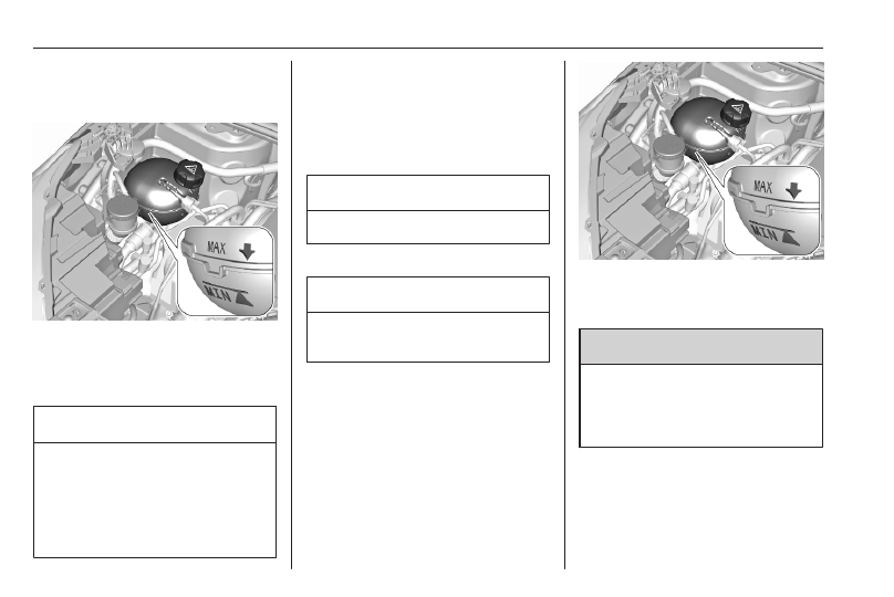
Coolant level BEV

If the coolant level is at the MIN mark

or below, seek the assistance of a

workshop to have the engine coolant

topped up.

Caution

Using the wrong engine coolant

can cause severe damages to the

high voltage battery. Only

experienced mechanics are

allowed to open the coolant

reservoir and to top up coolant.

Propulsion types 

3

 4.

Coolant level ICE

The factory filled coolant provides

freeze protection down to approx.

-37 °C.

Caution

Only use approved antifreeze.

Coolant and antifreeze 

3

 296.

Caution

A too low coolant level can cause

engine damage.

If the cooling system is cold, the

coolant level should be above the

MIN mark. Top up if the level is low.

9

Warning

Allow the engine to cool before

opening the cap. Carefully open

the cap, relieving the pressure

slowly.

To top up, use a 1:1 mixture of

released coolant concentrate mixed

with clean tap water. If no coolant

concentrate is available, use clean

tap water. Install the cap tightly. Have

Vehicle care

263

the coolant concentration checked

and have the cause of the coolant

loss remedied by a workshop.

Washer fluid

Fill with clean water mixed with a

suitable quantity of approved

windscreen washer fluid which

contains antifreeze.

Caution

Only washer fluid with a sufficient

antifreeze concentration provides

protection at low temperatures or

a sudden drop in temperature.

Washer fluid 

3

 296.

Brakes

Depending on the driving style, the

brake wear may vary significantly.The

brake wear may increase when the

vehicle is driven over short distances,

e.g. in the city.
It may be necessary to have the

condition of the brakes checked, even

between vehicle services.
Unless there is a leak in the circuit, a

drop in the brake fluid level indicates

that the brake pads are worn.
Once new brake linings are installed,

do not brake unnecessarily hard for

the first few journeys.

Brake fluid

9

Warning

Brake fluid is poisonous and

corrosive. Avoid contact with eyes,

skin, fabrics and painted surfaces.

The brake fluid level must be between

the MIN and MAX marks.
If fluid level is below MIN seek the

assistance of a workshop.
Brake and clutch fluid 

3

 296.

Vehicle battery

The vehicle battery is maintenance-

free provided that the driving profile

allows sufficient charging of the

battery. Short-distance-driving and

frequent engine starts can discharge

the battery. Avoid the use of

unnecessary electrical consumers.

264

Vehicle care

Batteries do not belong in household

waste. They must be disposed of at

an appropriate recycling collection

point.
Laying up the vehicle for more than

four weeks can lead to battery

discharge. Disconnect the clamp from

the negative terminal of the vehicle

battery.
Ensure the ignition is switched off

before connecting or disconnecting

the vehicle battery.
Battery discharge protection 

3

 91.

Replacing the vehicle battery

Notice

Any deviation from the instructions

given in this section may lead to

temporary deactivation or

disturbance of the stop-start system.

When the vehicle battery is being

replaced, please ensure that there

are no open ventilation holes in the

vicinity of the positive terminal. If a

ventilation hole is open in this area, it

must be closed off with a dummy cap,

and the ventilation in the vicinity of the

negative terminal must be opened.
Ensure that the battery is always

replaced by the same type of battery.
The vehicle battery has to be

replaced by a workshop.
Stop-start system 

3

 174.

Charging the vehicle battery

9

Warning

On vehicles with stop-start

system, ensure that the charging

potential does not exceed 14.6 V

when using a battery charger.

Otherwise the vehicle battery may

be damaged.

Jump starting 

3

 285.

Discharge protection

Battery voltage

When the vehicle battery voltage is

running low, a warning message will

appear in the Driver Information

Centre.
When the vehicle is being driven, the

load reduction function temporarily

deactivates certain functions, such as

the air conditioning, the heated rear

window, heated steering wheel, etc.
The deactivated functions are

reactivated automatically as soon as

conditions permit.

Idle boost

If charging of the vehicle battery is

required due to battery condition, the

power output of the generator must

be increased. This will be achieved by

an idle boost which may be audible.
A message appears in the Driver

Information Centre.

Power outlet

The power outlets are deactivated in

the event of low vehicle battery

voltage.

Vehicle care

265

Warning label

Meaning of symbols:

● No sparks, naked flames or

smoking.

● Always shield eyes. Explosive

gases can cause blindness or

injury.

● The vehicle battery contains

sulphuric acid which could cause

blindness or serious burn

injuries.

● Keep the vehicle battery out of

reach of children.

● See the Owner's Manual for

further information.

● Explosive gas may be present in

the vicinity of the vehicle battery.

Power saving mode

This mode deactivates electrical

consumers to avoid excessive

discharging of the vehicle battery.

These consumers, such as the

Infotainment system, windscreen

wipers, low beam headlights,

courtesy light, etc. can be used for a

total maximum time of about

40 minutes after ignition is switched

off.

Changing into power saving mode

When power saving mode is

activated, a message appears in the

Driver Information Centre.
An active telephone call using the

hands-free option will be maintained

for around 10 minutes longer.

Deactivating power saving mode

Power saving mode is deactivated

automatically when the engine is

restarted. Run the engine for a

sufficient charge:

● for less than 10 minutes to use

the consumers for approx.

5 minutes

● for more than 10 minutes to use

the consumers for up to approx.

30 minutes

Heating functionalities

Notice

Individual heating functionalities,

such as heated seats or heated

steering wheel, may be temporarily

unavailable in the event of electrical

loading constraints. Functions will

be resumed after some minutes.

266

Vehicle care

High voltage battery

To preserve the range and the

durability of the high voltage battery,

the following is recommended:

● Whenever possible do not

charge the high voltage battery

more than 80%.

● Do not completely discharge the

high voltage battery.

● Do not store the vehicle for a long

period of non-use (more than 12

hours) when the high voltage

battery has a low or high charge

level. Prefer a charge level

between 20 and 40%.

● Limit the use of fast charging.
● Do not expose the vehicle to

temperatures below -30 °C and

above 60 °C for more than 24

hours.

● Avoid charging the vehicle at low

temperatures (except if the

vehicle ran more than 20

minutes) or above 30 °C.

● Do not use the high voltage

battery as a generator of energy.

● Do not use a generator to

recharge the high voltage

battery.

Vehicle storage 

3

 257.

Leakage

Damage to the high voltage battery

could result in the leakage of toxic

gases or fluids either immediately or

later. The following is recommended:

● Always inform the fire and

emergency services in the event

of an incident, that the vehicle is

equipped with a high voltage

battery.

● Never touch the liquids leaking

from the high voltage battery.

● Do not inhale the gases emitted

by the high voltage battery which

are toxic.

● Move away from the vehicle in

the event of incident or accident,

the gases emitted being

flammable and could cause a

fire.

● Too low a coolant level must be

topped up and the cause of the

coolant loss remedied by a

workshop.

Diesel fuel system bleeding

If the tank has been run dry, the diesel

fuel system must be bled. Refuel at

least five litres diesel. Switch on the

ignition for about 60 seconds and

switch off again. Then crank the

engine. If the engine does not start

directly, repeat this process a few

times. If the engine then fails to start,

seek the assistance of a workshop.

Vehicle care

267

Wiper blade replacement

Windscreen

Switch off ignition.
Within one minute after switching off

ignition, operate the wiper lever to

position the wiper blades vertically on

the windscreen.
Lift the wiper arm until it stays in the

raised position, press button to

disengage the wiper blade and

remove.
Attach the new wiper blade to the

wiper arm and push until it engages.
Lower wiper arm carefully.

To return the wiper arms to their

original position, switch on the ignition

and operate the wiper lever.

Rear window

Lift wiper arm. Disengage wiper blade

as shown in illustration and remove.
Attach the wiper blade slightly angled

to the wiper arm and push until it

engages.
Lower wiper arm carefully.

Bulb replacement

Before replacing a bulb, ensure that

all exterior and interior lights and the

ignition are switched off.
Only hold a new bulb at the base. Do

not touch the bulb glass with bare

hands.
Use only the same bulb type for

replacement.
Replace headlight bulbs from within

the engine compartment.

Bulb check

After a bulb replacement switch on

the ignition, operate and check the

lights.

Halogen headlights

Halogen headlights with separate

bulbs for low beam and high beam /

daytime running light.

268

Vehicle care

Low beam (1) outer bulb.
High beam / daytime running light (2)

inner bulb.

Low beam (1)

1. Remove the protective cover by

pulling.

2. Withdraw the bulb socket from the

reflector housing.

3. Detach the bulb from the bulb

socket and replace the bulb.

4. Insert the bulb socket into the

reflector housing.

5. Fit the protective cover on.

High beam / daytime running light

(2)

1. Remove the protective cover by

pulling.

Vehicle care

269

2. Rotate the bulb socket

anticlockwise to disengage and

withdraw from the reflector.

3. Insert the new bulb socket into the

reflector housing.

4. Fit the protective cover on.

LED headlights

Headlights for low and high beam,

daytime running lights and turn lights

are designed as LEDs and cannot be

changed.
Have lights repaired by a workshop in

case of failure.

Front fog lights

Have lights repaired by a workshop in

case of failure.

Front turn lights

Turn light (1) outer bulb.

1. Remove the protective cover by

pulling.

2. Withdraw the bulb socket from the

reflector housing.

270

Vehicle care

3. Detach the bulb from the bulb

socket and replace the bulb.

4. Insert the bulb socket into the

reflector housing.

5. Fit the protective cover on.

Tail lights

LED tail lights

Have lights repaired by a workshop in

case of failure.

Light assembly in the body

1. Open the tailgate then remove the

access cover on the relevant side.

2. Slacken the lamp fixing nut using

a box spanner or socket.
To avoid losing the nut if it drops

into the wing trim, first place a

cloth below it.

3. Manually unscrew and remove

the lamp fixing nut.

4. Carefully withdraw tail light

assembly from the recess and

remove.

5. Detach the cable from the

retainer.

Vehicle care

271

6. Press the five retaining lugs and

remove the bulb carrier from the

light assembly.

7. Remove and replace the bulbs:

Tail light / brake light (1)
Turn light (2)
Reverse light (3)

8. Insert the bulb carrier into the light

assembly. Attach plug to the light

assembly. Fit the light assembly in

the recess and tighten the lamp

fixing nut from the inside. Attach

the cover.

Rear fog light

1. Turn the bulb holder anticlockwise

and remove it from the reflector

housing.

2. Slightly press down the bulb, turn

it anticlockwise and remove it

from the socket.

3. Replace and insert the new bulb

into socket by turning clockwise.

4. Insert the bulb socket into the

reflector and turn clockwise.

Centre high-mounted brake light

Have lights repaired by a workshop in

case of failure.

Number plate light

Have lights repaired by a workshop in

case of failure.

272

Vehicle care

Interior lights

Have the following bulbs replaced by

a workshop:

● courtesy light, reading lights
● load compartment light
● instrument panel illumination

Electrical system

Fuses

A defective fuse must be replaced by

a workshop.

Vehicle tools

Tools

Vehicles with spare wheel

Open the load compartment.

The tools are located in the tool bag:

● Jack (1)
● Wheel wrench (2)
● Towing eye (3)
● Wheel bolt cover remover (4)
● Chock (5)
● Adapter for the locking wheel

nuts (6)

Vehicle care

273

Vehicles without spare wheel

The towing eye is located in a box

below the floor cover in the load

compartment.
Tyre repair kit 

3

 277.

Wheels and tyres

Tyre condition, wheel condition

Drive over edges slowly and at right

angles if possible. Driving over sharp

edges can cause tyre and wheel

damage. Do not trap tyres on the kerb

when parking.
Regularly check the wheels for

damage. Seek the assistance of a

workshop in the event of damage or

unusual wear.

Winter tyres

Winter tyres improve driving safety at

temperatures below 7 °C and should

therefore be fitted on all wheels.
In accordance with country-specific

regulations, affix the speed sticker in

the driver's field of view, if the tyre

speed code is below the maximum

speed of the vehicle.
All tyre sizes are permitted as winter

tyres 

3

 304.

Tyre designations

E.g. 225/55 R 18 98 V
225 : tyre width, mm

55 : cross-section ratio (tyre height

to tyre width), %

R

: belt type: Radial

RF : type: RunFlat

18 : wheel diameter, inches

98 : load index e.g. 98 is equivalent

to 750 kg

V

: speed code letter

Speed code letter:
Q : up to 100 mph

S : up to 112 mph

T : up to 118 mph

H : up to 130 mph

V : up to 150 mph

W : up to 168 mph
Choose a tyre appropriate for the

maximum speed of your vehicle.
The maximum speed is achievable at

kerb weight with driver (75 kg) plus

125 kg payload. Optional equipment

could reduce the maximum speed of

the vehicle.

274

Vehicle care

Directional tyres

Directional tyres should be mounted

so that they rotate in the correct

direction. The proper rotation

direction is indicated by a symbol

(e.g. an arrow) on the sidewall.

Tyre pressure

Check the pressure of cold tyres at

least every 14 days and before any

long journey. Do not forget the spare

wheel. This also applies to vehicles

with tyre deflation detection system.

The tyre pressure information label

indicates the original equipment tyres

and the correspondent tyre

pressures.
The tyre pressure data refers to cold

tyres. It applies to summer and winter

tyres.
Always inflate the full size spare tyre

to the pressure specified for full load.
Incorrect tyre pressures will impair

safety, vehicle handling, comfort and

fuel economy and will increase tyre

wear.
The driver is responsible for correct

adjustment of tyre pressure.
The tyre pressure tables show all

possible tyre combinations 

3

 304.

For the tyres approved for your

vehicle, refer to the EEC Certificate of

Conformity provided with your vehicle

or other national registration

documents.
For the correct tyre pressure value,

follow the procedure below:

1. Identify the engine identifier code.

Engine data 

3

 301.

2. Identify the respective tyre.

9

Warning

If the pressure is too low, this can

result in considerable tyre warm-

up and internal damage, leading to

tread separation and even to tyre

blow-out at high speeds.

9

Warning

For specific tyres the

recommended tyre pressure as

shown in the tyre pressure table

may exceed the maximum tyre

pressure as indicated on the tyre.

Never exceed the maximum tyre

pressure as indicated on the tyre.

Temperature dependency

The tyre pressure depends on the

temperature of the tyre. During

driving, tyre temperature and

pressure increase. Tyre pressure

values provided on the tyre

information label and tyre pressure

chart are valid for cold tyres, which

means at 20 °C.

Vehicle care

275

The pressure increases by nearly

1.5 psi for a 10 °C temperature

increase. This must be considered

when warm tyres are checked.

Tyre deflation detection

system

The tyre deflation detection system

continually checks the rotation speed

of all four wheels and warns on low

tyre pressure condition once vehicle

is driving. This is achieved by

comparing tyre rolling circumference

with reference values and further

signals.
If a tyre loses pressure the control

indicator 

w

 illuminates and a warning

message is displayed in the Driver

Information Centre.
Control indicator 

w


3

 72.

In this case reduce speed, avoid

sharp cornering and strong braking.

Stop at next safe opportunity and

check tyre pressure.
After adjusting tyre pressure initialise

system to extinguish the control

indicator and restart system.

If the failure continues to be

displayed, contact a workshop. The

system is inoperable when the ABS or

Electronic Stability Control has a

malfunction or a temporary spare

wheel is used. Once the tyre has been

refitted, check the tyre pressure with

cold tyres and initialise the system.

Caution

Deflation detection system warns

just about low tyre pressure

condition and does not replace

regular tyre maintenance by the

driver.

System initialisation

After tyre pressure correction or

wheel change, the system must be

initialised to learn new circumference

reference values:

1. Always ensure that all four tyres

have correct tyre pressure

3

 304.

2. Apply parking brake.

3. Initialise the system via the Info

Display 

3

 77.

4. Reset is confirmed by pop-up

indication.

After initialisation system

automatically calibrates to new tyre

pressures during driving. After longer

drive the system will adopt and

monitor new pressures.
Always check tyre pressure with cold

tyres.
System has to be reinitialised when:

● Tyre pressure has been changed
● Load condition has been

changed

● Wheels have been swapped or

exchanged

The system will not warn

instantaneously on a tyre blow out or

a rapid deflation. This is due to

required calculation time.

Tread depth

Check tread depth at regular

intervals.

276

Vehicle care

Tyres should be replaced for safety

reasons at a tread depth of 2-3 mm

(4 mm for winter tyres).
For safety reasons, it is

recommended that the tread depth of

the tyres on one axle should not vary

by more than 2 mm.

The legally permissible minimum

tread depth (1.6 mm) has been

reached when the tread has worn

down as far as one of the tread wear

indicators (TWI). Their position is

indicated by markings on the

sidewall.

If there is more wear at the front than

the rear, swap round front wheels and

rear wheels periodically. Ensure that

the direction of rotation of the wheels

remains the same.
Tyres age, even if they are not used.

We recommend tyre replacement

every 6 years.

Changing tyre and wheel

size

If tyres of a different size than those

fitted at the factory are used, it may be

necessary to reprogramme the

system and make other vehicle

modifications.
Have the label with tyre pressures

replaced.

9

Warning

The use of unsuitable tyres or

wheels may lead to accidents and

will invalidate the vehicle

operating permit.

Wheel covers

Wheel covers and tyres that are

factory approved for the respective

vehicle and comply with all of the

relevant wheel and tyre combination

requirements must be used.
If the wheel covers and tyres used are

not factory approved, the tyres must

not have a rim protection ridge.
Wheel covers must not impair brake

cooling.

9

Warning

Use of unsuitable tyres or wheel

covers could lead to sudden

pressure loss and thereby

accidents.

Vehicles with steel wheels: When

using locking wheel nuts, do not

attach wheel covers.

Vehicle care

277

Tyre chains

Tyre chains are only permitted on the

front wheels.
Always use fine mesh chains that add

no more than 9 mm to the tyre tread

and the inboard sides (including chain

lock).

9

Warning

Damage may lead to tyre blowout.

Tyre chains are permitted on tyres of

size 185/65R15 and 195/55R16.

Temporary spare wheel

The use of tyre chains is not permitted

on the temporary spare wheel.

Tyre repair kit

Minor damage to the tyre tread can be

repaired with the tyre repair kit.
Do not remove foreign bodies from

the tyres.
Tyre damage exceeding 4 mm or that

is at tyre's sidewall cannot be repaired

with the tyre repair kit.
Depending on version, there are two

different tyre repair kits (Type A and

Type B).

9

Warning

Do not drive faster than 50 mph.
Do not use for a lengthy period.
Steering and handling may be

affected.

In the case of a flat tyre:
Apply the parking brake and engage

first gear, reverse gear or P.

Type A

Type B
The tyre repair kit is in the load

compartment below the floor cover.

278

Vehicle care

1. Remove the sealant bottle and the

compressor.

2. Pull speed limit label from sealant

bottle and place it in driver's

visible area.

3. Remove the electrical connection

cable (1) and air hose (2) from the

stowage compartments on the

underside of the compressor.

4. Type A: Open sealant bottle and

lift the lid.

5. Type A: First, insert sealant bottle

into the compresor and align the

triangle symbols. Then, push

down sealant bottle and turn it to

the lock position.

Type B: Screw the compressor air

hose to the connection on the

sealant bottle.

6. Type B: Fit the sealant bottle into

the bracket on the compressor.

7. Set the compressor near the tyre

in such a way that the sealant

bottle is upright.

8. Unscrew valve cap from defective

tyre.

Vehicle care

279

9. Screw the filler hose to the tyre

valve.

10. The switch on the compressor

must be set to 

J

.

11. Connect the compressor plug to

the 12 V power outlet or cigarette

lighter socket 

3

 58.

To avoid discharging the vehicle

battery, we recommend to use the

tyre repair kit only when the

combustion engine is running or

when the electric engine is ready.

12. Set the rocker switch on the

compressor to I. The tyre is filled

with sealant.

13. The compressor pressure gauge

briefly indicates up to

600 kPa (6 bar) whilst the sealant

bottle is emptying (approx.

30 seconds). Then the pressure

starts to drop.

14. All of the sealant is pumped into

the tyre. Then the tyre is being

inflated.

15. The prescribed tyre pressure

should be obtained within ten

minutes.
Tyre pressure 

3

 304.

When the correct pressure is

obtained, switch off the

compressor.
If the prescribed tyre pressure is

not obtained within ten minutes,

remove the tyre repair kit. Move

the vehicle one tyre rotation.

Reattach the tyre repair kit and

continue the filling procedure for

ten minutes. If the prescribed tyre

pressure is still not obtained, the

tyre is too badly damaged. Seek

the assistance of a workshop.

Drain excess tyre pressure with

the button on the air hose.
Do not run the compressor longer

than ten minutes.

280

Vehicle care

16. Detach the tyre repair kit. Remove

sealant bottle from compressor.

Screw the filler hose to the free

connection of the sealant bottle.

This prevents sealant from

escaping. Stow tyre repair kit in

load compartment.

17. Remove any excess sealant

using a cloth.

18. Continue driving immediately so

that sealant is evenly distributed

in the tyre. Drive between

13 mph and 37 mph. After driving

approx. 3 miles but no more than

ten minutes, stop and check tyre

pressure. Screw compressor air

hose directly onto tyre valve when

doing this. Fill tyre as described

before. Drain excess tyre

pressure with the button on the air

hose.
If tyre pressure hasn't decreased

under 200 kPa (2 bar), set it to the

correct value. Otherwise the

vehicle must not be used. Seek

assistance of a workshop.
Repeat the checking procedure

once more after driving further

6 miles but no more than ten

minutes to check that there is no

more loss of pressure.
If the tyre pressure has fallen

below 200 kPa (2 bar), the vehicle

must not be used. Seek the

assistance of a workshop.

19. Stow away tyre repair kit in load

compartment.

Notice

The driving characteristics of the

repaired tyre are severely affected,

therefore have this tyre replaced.
If unusual noise is heard or the

compressor becomes hot, turn

compressor off for at least 30 min.
The built-in safety valve opens at a

pressure of seven bar (102 psi).
Note the expiry date of the kit. After

this date its sealing capability is no

longer guaranteed. Pay attention to

storage information on sealant

bottle.
Replace the used sealant bottle.

Dispose of the bottle as prescribed

by applicable laws.
The compressor and sealant can be

used from approx. -30 °C.

Wheel changing

Make the following preparations and

observe the following information:

● Park the vehicle on a level, firm

and non-skid surface. The front

wheels must be in the straight-

ahead position.

● If necessary, place a chock under

the wheel diagonally opposite the

wheel to be changed.

● Apply the parking brake and

engage first gear, reverse gear or

P.

● If the ground on which the vehicle

is standing is soft, a solid board

(max. 1 cm thick) should be

placed under the jack.

● Take heavy objects out of the

vehicle before jacking up.

● No people or animals may be in

the vehicle when it is jacked-up.

● Never crawl under a jacked-up

vehicle.

● Do not start the vehicle when it is

raised on the jack.

● Before screwing in the wheel

bolts, clean them.

Vehicle care

281

9

Warning

Do not grease wheel bolts.

Tightening torques

Caution

If the vehicle is equipped with alloy

wheel rims, tighten the wheel bolts

manually at least for the first five

turns.

Depending on the wheel rim material,

two different bolts are available.

Tightening torque for alloy wheel rims

is 115 Nm.

Tightening torque for steel wheel rims

is 115 Nm.

9

Warning

Ensure to use always the correct

wheel bolts if changing the

wheels. When installing the spare

wheel for temporary usage, the

bolts for alloy wheel rims can also

be used.

Jacking positions

The jacking positions shown refer to

the use of lifting arms and accessory

jacks used for changing winter /

summer tyres.

The rear arm position of the lifting

platform is centrically under the

relevant vehicle jacking point.

282

Vehicle care

The front arm position of the lifting

platform is centrically under the

relevant vehicle jacking point.

Spare wheel

The spare wheel can be classified as

a temporary spare wheel depending

on the size compared to the other

mounted wheels and country

regulations. In this case, a

permissible maximum speed applies,

even though no label at the spare

wheel indicates this.
If there is a label on the spare wheel,

the permissible speed still depends

on the country regulations.
Only mount one temporary spare

wheel. Take curves slowly. Do not

use for a long period of time.

Caution

The use of a spare wheel that is

smaller than the other wheels or in

combination with winter tyres

could affect driveability. Have the

defective tyre replaced as soon as

possible.

The spare wheel is located in the load

compartment beneath the floor

covering.
To remove:

1. Open the floor cover 

3

 48.

2. The temporary spare wheel is

secured with a wing nut. Unscrew

nut and take out the spare wheel.

3. When, after a wheel change, no

wheel is placed in the spare wheel

well, tighten the wing nut and

close floor cover.

4. After wheel change back to full

size wheel, place the temporary

spare wheel outside up in the well

and secure with the wing nut.

Fitting the spare wheel

Make the following preparations and

observe the following information:

● Park the vehicle on a level, firm

and non-skid surface. The front

wheels must be in the straight-

ahead position.

● If necessary, place a chock under

the wheel diagonally opposite the

wheel to be changed.

● Apply the parking brake and

engage first gear, reverse gear or

P.

● Remove the spare wheel.
● Never change more than one

wheel at once.

● Use the jack only to change

wheels in case of puncture, not

for seasonal winter or summer

tyre change.

● The jack is maintenance-free.
● If the ground on which the vehicle

is standing is soft, a solid board

(max. 1 cm thick) should be

placed under the jack.

● Take heavy objects out of the

vehicle before jacking up.

Vehicle care

283

● No people or animals may be in

the vehicle when it is jacked-up.

● Never crawl under a jacked-up

vehicle.

● Do not start the vehicle when it is

raised on the jack.

● Before screwing in the wheel

bolts, clean them.

9

Warning

Do not grease wheel bolts.

9

Warning

Ensure to use always the correct

wheel bolts if changing the

wheels. When installing the spare

wheel for temporary usage, the

bolts for alloy wheel rims can also

be used.

● Note that the spare wheel is

secured by the conical contact of

each bolt if the wheel bolts for the

alloy wheel rims are used. In this

case, the washers do not come

into contact with the spare wheel.

1. Disengage wheel bolt caps with

the wheel bolt cover remover.
Vehicle tools 

3

 272.

Steel wheels rims with cover: Pull

off the wheel cover.

2. Attach the wheel wrench and

loosen each wheel bolt by half a

turn.
The wheels might be protected by

locking wheel nuts. To loosen

these specific nuts first attach the

adapter onto the head of the nut

before installing the wheel

wrench. The adapter is located in

the tool bag 

3

 272.

284

Vehicle care

3. Ensure the jack is correctly

positioned under the relevant

vehicle jacking point.

4. Set the jack to the necessary

height. Position it directly below

the jacking point in a manner that

prevents it from slipping.

Ensure that the edge of the body

fits into the notch of the jack.

With the jack correctly aligned,

jack up until wheel is clear of the

ground.

5. Unscrew the wheel nuts.
6. Change the wheel.
7. Screw on the wheel nuts.
8. Lower the vehicle and remove

jack.

9. Install the wheel wrench ensuring

that it is located securely and

tighten each bolt in a crosswise

sequence.
Tightening torque for 15" is

100 Nm and for 16" is 115 Nm.
If the vehicle is equipped with

alloy wheel rims, note that the

wheel bolts can also be used for

the spare wheel with steel rims. In

this case, the spare wheel is

secured by the conical contact of

each bolt.

10. Vehicles with wheel cover: Align

the valve hole in the wheel cover

with the tyre valve before

installing.
Install wheel nut caps.

Vehicle care

285

11. Stow the replaced wheel and the

vehicle tools.

12. Check the tyre pressure of the

installed tyre and the wheel nut

torque as soon as possible.

Stowing a damaged full size

wheel in the load compartment

The damaged full size wheel can be

stowed in the spare wheel well. To

secure the wheel:

1. Remove centre cap with the brand

emblem by pushing from the

inside.

2. Position the wheel outside down

in the wheel well.

3. Secure the defective wheel with

the wing nut.

4. Depending on the tyre size, the

floor cover can be placed on the

projecting wheel.

Jump starting

Do not start with quick charger.
A vehicle with a discharged vehicle

battery can be started using jump

leads and the vehicle battery of

another vehicle.

Caution

Never jump start another vehicle

with an electric vehicle.

9

Warning

Be extremely careful when starting

with jump leads. Any deviation

from the following instructions can

lead to injuries or damage caused

by battery explosion or damage to

the electrical systems of both

vehicles.

286

Vehicle care

9

Warning

Avoid contact of the battery with

eyes, skin, fabrics and painted

surfaces. The fluid contains

sulphuric acid which can cause

injuries and damage in the event

of direct contact.

● Never expose the vehicle battery

to naked flames or sparks.

● A discharged vehicle battery can

already freeze at a temperature

of 0 °C. Defrost the frozen battery

before connecting jump leads.

● Wear eye protection and

protective clothing when

handling a battery.

● Use a booster battery with the

same voltage (12 V). Its capacity

(Ah) must not be much less than

that of the discharged vehicle

battery.

● Use jump leads with insulated

terminals and a cross section of

at least 16 mm

2

 (25 mm

2

 for

diesel engines).

● Do not disconnect the discharged

vehicle battery from the vehicle.

● Switch off all unnecessary

electrical consumers.

● Do not lean over the vehicle

battery during jump starting.

● Do not allow the terminals of one

lead to touch those of the other

lead.

● The vehicles must not come into

contact with each other during

the jump starting process.

● Apply the parking brake,

transmission in neutral,

automatic transmission in P.

Lead connection order:

1. Connect the red lead to the

positive terminal of the booster

battery.

2. Connect the other end of the red

lead to the positive terminal of the

discharged battery.

3. Connect the black lead to the

negative terminal of the booster

battery.

4. Connect the other end of the black

lead to a vehicle grounding point

of your vehicle in the engine

compartment.

Route the leads so that they cannot

catch on rotating parts in the engine

compartment.
To start the engine:

1. Start the engine of the vehicle

providing the jump.

2. After 5 minutes, start the other

engine. Start attempts should be

made for no longer than

15 seconds at an interval of

1 minute.

Vehicle care

287

3. Allow both engines to idle for

approx. 3 minutes with the leads

connected.

4. Switch on electrical consumers

e.g. headlights, heated rear

window.

5. Reverse above sequence exactly

when removing leads.

Towing

Towing the vehicle

Remove the cap.
The towing eye is stowed with the

vehicle tools 

3

 272.

Screw in the towing eye as far as it will

go until it stops in a horizontal

position.
Attach the tow rod to the towing eye.
The towing eye must only be used for

towing and not for recovering the

vehicle.
Switch on ignition to permit operation

of brake lights, horn, windscreen

wiper and, depending on version, to

release the steering wheel lock.

288

Vehicle care

Caution

Deactivate the driver assistance

systems like active emergency

braking 

3

 212, otherwise the

vehicle may automatically brake

during towing.

Switch the selector lever to neutral.
Release the parking brake.

Caution

Drive slowly. Do not drive jerkily.

Excessive tractive force can

damage the vehicle.

When the engine is not running,

considerably more force is needed to

brake and steer.
To prevent the entry of exhaust gases

from the towing vehicle, switch on the

air recirculation and close the

windows.

When towing a BEV or a vehicle

equipped with an automatic

transmission, transport the vehicle on

a platform or tow it with the front

wheels lifted.
After towing, unscrew the towing eye.
Insert cap with the flange into the

recess and fix cap by pushing.
Propulsion types 

3

 4.

Towing another vehicle

Remove the cap.
The towing eye is stowed with the

vehicle tools 

3

 272.

Vehicle care

289

Screw in the towing eye as far as it will

go until it stops in a horizontal

position.
Attach a tow rope – or better still a tow

rod – to the towing eye.
The towing eye must only be used for

towing and not for recovering a

vehicle.

Caution

Drive slowly. Do not drive jerkily.

Excessive tractive force can

damage the vehicle.

After towing, unscrew the towing eye.
Insert cap with the upper flange into

the recess and fix cap by pushing.

Appearance care

Exterior care

Locks

The locks are lubricated at the factory

using a high quality lock cylinder

grease. Use a de-icing agent only

when absolutely necessary, as this

has a degreasing effect and impairs

lock function. After using a de-icing

agent, have the locks regreased by a

workshop.

Washing

The paintwork of your vehicle is

exposed to environmental influences.
Bird droppings, dead insects, resin,

pollen and the like should be cleaned

off immediately, as they contain

aggressive constituents which can

cause paint damage.
If using a vehicle wash, comply with

the vehicle wash manufacturer's

instructions. The windscreen wiper

and rear window wiper must be

switched off. Remove antenna and

external accessories such as roof

racks etc.
If you wash your vehicle by hand,

make sure that the insides of the

wheel housings are also thoroughly

rinsed out.
Clean edges and folds on opened

doors and the bonnet as well as the

areas they cover.
Clean bright metal mouldings with a

cleaning solution approved for

aluminium to avoid damages.

Caution

Always use a cleaning agent with

a pH value of 4 to 9.
Do not use cleaning agents on hot

surfaces.

Do not clean the engine compartment

with a steam-jet or high-pressure jet

cleaner.
Thoroughly rinse and leather-off the

vehicle. Rinse leather frequently. Use

separate leathers for painted and

glass surfaces: remnants of wax on

the windows will impair vision.

290

Vehicle care

Have the door hinges of all doors

greased by a workshop.

Exterior lights

Headlight and other light covers are

made of plastic. Do not use any

abrasive or caustic agents, do not use

an ice scraper, and do not clean them

dry.

Polishing and waxing

Polishing is necessary only if the paint

has become dull or if solid deposits

have become attached to it.
Plastic body parts must not be treated

with wax or polishing agents.

Windows and wiper blades

Switch off wipers before handling in

their areas.
Use a soft lint-free cloth or chamois

leather together with window cleaner

and insect remover.
When cleaning the rear window from

inside, always wipe in parallel to the

heating element to prevent damage.

For mechanical removal of ice, use a

sharp-edged ice scraper. Press the

scraper firmly against the glass so

that no dirt can get under it and

scratch the glass.
Clean smearing wiper blades with a

soft cloth and window cleaner. Also

make sure to remove any residues

such as wax, insect residues and

similar from the window.
Ice residues, pollution and continuous

wiping on dry windows will damage or

even destroy the wiper blades.

Wheels and tyres

Do not use high-pressure jet

cleaners.
Clean rims with a pH-neutral wheel

cleaner.
Rims are painted and can be treated

with the same agents as the body.

Paintwork damage

Rectify minor paintwork damage with

a touch-up pen before rust forms.

Have more extensive damage or rust

areas repaired by a workshop.

Underbody

Some areas of the vehicle underbody

have a PVC undercoating while other

critical areas have a durable

protective wax coating.
After the underbody is washed, check

the underbody and have it waxed if

necessary.
Bitumen / rubber materials could

damage the PVC coating. Have

underbody work carried out by a

workshop.
Before and after winter, wash the

underbody and have the protective

wax coating checked.

Towing equipment

Do not clean the coupling ball bar with

a steam-jet or high-pressure jet

cleaner.

Vehicle care

291

Interior care

Interior and upholstery

Only clean the vehicle interior,

including the instrument panel fascia

and panelling, with a dry cloth or

interior cleaner.
Clean the leather upholstery with

clear water and a soft cloth. In case of

heavy soiling, use leather care.
The instrument cluster and the

displays should only be cleaned using

a soft damp cloth. If necessary use a

weak soap solution.
Clean fabric upholstery with a

vacuum cleaner and brush. Remove

stains with an upholstery cleaner.
Clothing fabrics may not be

colourfast. This could cause visible

discolourations, especially on light-

coloured upholstery. Removable

stains and discolourations should be

cleaned as soon as possible.
Clean seat belts with lukewarm water

or interior cleaner.

Caution

Close Velcro fasteners as open

Velcro fasteners on clothing could

damage seat upholstery.
The same applies to clothing with

sharp-edged objects, like zips or

belts or studded jeans.

Plastic and rubber parts

Plastic and rubber parts can be

cleaned with the same cleaner as

used to clean the body. Use interior

cleaner if necessary. Do not use any

other agent. Avoid solvents and petrol

in particular. Do not use high-

pressure jet cleaners.

Floor mats

9

Warning

If a floor mat has the wrong size or

is not properly installed, it can

interfere with the accelerator pedal

and/or brake pedal, what can

cause unintended acceleration

and/or increased stopping

distance which can cause a crash

and injury.

Use the following guidelines for

proper floor mat usage.

● The original equipment floor mats

were designed for this vehicle. If

the floor mats need to be

replaced, it is recommended to

buy certified floor mats which fit

properly and are fixed by the

retainers on the driver side.

Always check that the floor mats

do not interfere with the pedals.

● Use the floor mat with the correct

side up. Do not turn it over.

● Do not place anything on top of

the driver side floor mat.

● Use only a single floor mat on the

driver side.

Inserting floor mats

The driver side floor mat is held in

place by two retainers.
To install:

1. Move the seat backwards as far

as possible.

292

Vehicle care

2. Align slots in the mat with the

retainers, as shown.

3. Push the mat to the floor.

Removing floor mats

To remove:

1. Move the seat backwards as far

as possible.

2. Remove the mat.

Service and maintenance

293

Service and

maintenance

General information ................... 293

Service information .................. 293

Recommended fluids, lubricants

and parts .................................... 296

Recommended fluids and

lubricants ................................ 296

General information

Service information

In order to ensure economical and

safe vehicle operation and to

maintain the value of your vehicle, it

is of vital importance that all

maintenance work is carried out at the

proper intervals as specified.
The detailed, up-to-date service

schedule for your vehicle is available

at the workshop.
Severe operating conditions exist if

one or more of the following

circumstances occur frequently: Cold

starting, stop and go operation, e.g.

for taxis and police vehicles, trailer

operation, mountain driving, driving

on poor and sandy road surfaces,

increased air pollution, presence of

airborne sand and high dust content,

driving at high altitude and large

variations of temperature.
Under these severe operating

conditions, certain service work may

be required more frequently than the

regular service interval indicated in

the service display. Contact a

workshop for customised service

schedules.
Service display 

3

 64.


Content      ..     7      8      9      10     ..