Vauxhall Astra L (2023 year). Manual in english - page 7
 

  Index      Manuals     Vauxhall Astra L (2023 year). Manual in english


Search            copyright infringement  


Content      ..     5      6      7      8     ..


Vauxhall Astra L (2023 year). Manual in english - page 7


198

Driving and operating

At temperatures below -15 °C, it is

recommended to park the car in a

heated garage.
Arctic grade diesel fuel can be used

at extremely low temperatures below

-20 °C. Using this fuel grade in warm

or hot climates is not recommended

and may cause engine stalling, poor

starting or damage on the fuel

injection system.

Refuelling

9

Danger

Before refuelling, switch off

ignition and any external heaters

with combustion chambers.
Follow the operating and safety

instructions of the filling station

when refuelling.

9

Danger

Fuel is flammable and explosive.

No smoking. No naked flames or

sparks.

If you can smell fuel in your

vehicle, have the cause of this

remedied immediately by a

workshop.

A label with symbols at the fuel filler

flap is indicating the allowed fuel

types. In Europe the pump nozzles of

the filling stations are marked with

these symbols. Refuel only the

allowed fuel type.

Caution

In case of misfuelling, do not

switch on ignition.

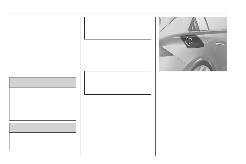
The fuel filler flap is located at right

rear side of vehicle.

The fuel filler flap can only be opened

if the vehicle is unlocked. Release the

fuel filler flap by pushing the flap.
To open the fuel filler flap of a PHEV,

a depressurisation phase is required

to avoid the emission of fuel vapour.

This can take up to one minute.

Driving and operating

199

Press 

r

. After depressurisation the

fuel filler flap is unlocked and bounces

a bit.

Petrol and diesel refuelling

To open, turn the cap slowly

anticlockwise.

The fuel filler cap can be attached to

the hook on the fuel filler flap.
Place the nozzle in straight position to

the filler neck and press with slight

force to insert.
To refuel, switch on pump nozzle.
After the automatic cut-off, the tank

can be topped up by operating the

pump nozzle a maximum of two more

times.

Caution

Wipe off any overflowing fuel

immediately.

To close, turn the fuel filler cap

clockwise until it clicks.
Close the flap and allow it to engage.

Fuel filler cap

Only use genuine fuel filler caps.
Diesel-engined vehicles have special

fuel filler caps.

Fuel consumption - CO

2

-

Emissions

All values are combined values under

WLTP condition.
ICE

The fuel consumption is within a

range of 36 to 56 mpg.
The CO

2

 emission is within a range of

148 to 111 g/km.
PHEV

The fuel consumption is within a

range of 196 to 235 mpg.
The CO

2

 emission is within a range of

28 to 22 g/km.
Propulsion types 

3

 4.

200

Driving and operating

General information

For the values specific to your

vehicle, refer to the EEC Certificate of

Conformity provided with your vehicle

or other national registration

documents.
The determination of fuel

consumption is regulated by directive

R (EC) No. 715/2007 and No.

2017/1151 (in the latest applicable

version).
The specification of CO

2

 emission is

also a constituent of the directive.
The figures given must not be taken

as a guarantee for the actual fuel

consumption of a particular vehicle.

Furthermore, fuel consumption is

dependent on personal driving style

as well as road and traffic conditions.
All values are based on the EU base

model with standard equipment.
The calculation of fuel consumption

takes into account the vehicle's kerb

weight, ascertained in accordance

with the regulations. Optional

equipment may result in slightly

higher fuel consumption and

CO

2

 emission levels and a lower

maximum speed.

Trailer hitch

General information

Caution

For new vehicles, only tow a trailer

after having driven at least 620

miles.

Only use towing equipment that has

been approved for your vehicle.
Entrust retrofitting of towing

equipment to a workshop. It may be

necessary to make changes that

affect the cooling system, heat

shields or other equipment.
Fitting of towing equipment could

cover the opening of the towing eye.

If this is the case, use the coupling ball

bar for towing. Always keep the

coupling ball bar in the vehicle to have

it on hand if needed.

Driving and operating

201

Driving characteristics and

towing tips

Before attaching a trailer, lubricate

the coupling ball. However, do not do

so if a stabiliser, which acts on the

coupling ball, is being used to reduce

snaking movements.
During trailer towing do not exceed a

speed of 50 mph. A maximum speed

of 60 mph is only appropriate if an

oscillation damper is used and the

permissible gross trailer weight does

not exceed the vehicle's curb weight.
For trailers with low driving stability

and caravan trailers, the use of an

oscillation damper is strongly

recommended.
If the trailer starts snaking, drive more

slowly, do not attempt to correct the

steering and brake sharply if

necessary.
When driving downhill, drive in the

same gear as if driving uphill and

drive at a similar speed.
Adjust tyre pressure to the value

specified for full load 

3

 252.

Trailer towing

Trailer loads

The permissible trailer loads are

vehicle and engine-dependent

maximum values which must not be

exceeded. The actual trailer load is

the difference between the actual

gross weight of the trailer and the

actual coupling socket load with the

trailer coupled.
The permissible trailer loads are

specified in the vehicle documents. In

general, they are valid for gradients

up to 12%.
The permissible trailer load applies

up to the specified incline and at sea

level. Since engine power decreases

as altitude increases due to the air

becoming thinner, therefore reducing

climbing ability, the permissible gross

train weight also decreases by 10%

for every 1000 m of altitude. The

gross train weight does not have to be

reduced when driving on roads with

slight inclines (less than 8%, e.g.

motorways).

The permissible gross train weight

must not be exceeded. This weight is

specified on the identification plate

3

 245.

Vertical coupling load

9

Warning

If attaching accessories to the

trailer hitch such as bicycle

carriers, tow boxes etc., do comply

with the maximum permissible

vertical coupling load.
When using a bicycle carrier, do

not transport more than four

conventional bicycles or two

electric bicycles. Make sure to

place the heaviest bicycle as close

as possible to the vehicle.

The vertical coupling load is the load

exerted by the trailer on the coupling

ball. It can be varied by changing the

weight distribution when loading the

trailer.

202

Driving and operating

The maximum permissible vertical

coupling load (55 kg) is specified on

the towing equipment identification

plate and in the vehicle documents.
Always aim for the maximum vertical

coupling load, especially in the case

of heavy trailers. The vertical coupling

load should never fall below 25 kg.

Rear axle load

When the trailer is coupled and the

towing vehicle fully loaded, the

permissible rear axle load (see

identification plate or vehicle

documents) may be exceeded by

60 kg, the gross vehicle weight rating

must not be exceeded. If the

permissible rear axle load is

exceeded, a maximum speed of

60 mph applies.

Towing equipment

Caution

When operating without a trailer,

remove the coupling ball bar.

Stowage of coupling ball bar

The bag with the coupling ball bar is

stowed on the rear floor cover in the

load compartment.
Place the strap through the rear right

lashing eye, wrap around twice and

tighten the strap to secure the bag.

Fitting the coupling ball bar

Disengage and fold down the socket.

Remove the sealing plug from the

opening for the coupling ball bar and

stow it.

Driving and operating

203

Checking the tensioning of the

coupling ball bar

● Remove the protective flap of the

lock of the rotary knob and verify

whether the rotary knob is

unlocked.

● Red marking on rotary knob must

point towards white marking on

coupling ball bar.

● The gap between the rotary knob

and the coupling ball bar must be

approx. 5 mm.

Otherwise, the coupling ball bar must

be tensioned before being inserted:

● Unlock coupling ball bar by

turning the key to position 

c

.

● Pull out the rotary knob and turn

clockwise as far as it will go.

Inserting the coupling ball bar

204

Driving and operating

Insert the tensioned coupling ball bar

in the opening and push firmly

upwards until it audibly engages.
The rotary handle snaps back into its

original position resting against the

coupling ball bar without a gap.

9

Warning

Do not touch rotary handle during

insertion.

Lock the coupling ball bar by turning

the key to position 

e

. Remove the key

and close the protective flap.

Eye for break-away stopping cable

Attach the breakaway stopping cable

to the eye.

Check that the coupling ball bar is

correctly installed

● The green marking on the rotary

knob must point towards the

white marking on the coupling

ball bar.

● There must be no gap between

the rotary knob and the coupling

ball bar.

● The coupling ball bar must be

firmly engaged in the opening.

● The coupling ball bar must be

locked and the key removed.

9

Warning

Towing a trailer is permitted only

when a coupling ball bar is fitted

correctly. If the coupling ball bar

does not engage correctly, seek

the assistance of a workshop.

Dismounting the coupling ball bar

Hold the plug of the trailer and

disconnect it from the power outlet by

performing a a quarter turn and

pulling.
Disconnect the saftety cable of the

trailer from the safety eye of the

carrier.
Remove the trailer from the coupling

ball.
Put the protective cover over the

towing ball.
Open the protective flap of the lock

and turn the key to position 

c

 to

unlock the coupling ball bar.

Driving and operating

205

Pull out the rotary handle and turn

clockwise as far as it will go. Pull out

the coupling ball bar downwards.
Insert the sealing plug in opening.

Fold away the socket.

Trailer stability assist

If the system detects snaking

movements, engine power is reduced

and the vehicle / trailer combination is

selectively braked until the snaking

ceases. While system is working keep

steering wheel as still as possible.
The system operates from 37 mph to

99 mph.

9

Warning

In some situations, the system

may not detect trailer snaking, e.g.

when towing a light trailer. On

slippery or poor surfaces, the

system may not be able to prevent

sudden trailer snaking.

Trailer stability assist is a function of

the Electronic Stability Control 

3

 148.

206

Vehicle care

Vehicle care

General Information ................... 206

Accessories and vehicle

modifications .......................... 206

Vehicle storage ........................ 208

End-of-life vehicle recovery ..... 210

Vehicle checks ........................... 211

Performing work ...................... 211

Bonnet ..................................... 211

Engine oil ................................. 212

Engine coolant ......................... 213

Washer fluid ............................ 214

Brakes ..................................... 215

Brake fluid ............................... 215

Vehicle battery ......................... 215

High voltage battery ................ 217

Diesel fuel system bleeding ..... 218

Wiper blade replacement ........ 218

Bulb replacement ....................... 219
Electrical system ........................ 220

Fuses ....................................... 220

Vehicle tools .............................. 220

Tools ........................................ 220

Wheels and tyres ....................... 221

Winter tyres ............................. 221

Tyre designations .................... 221

Tyre pressure .......................... 222

Tyre deflation detection

system .................................... 223

Tread depth ............................. 224

Changing tyre and wheel size . 224

Wheel covers ........................... 224

Tyre chains .............................. 225

Tyre repair kit .......................... 225

Wheel changing ....................... 228

Spare wheel ............................ 230

Jump starting ............................. 233
Towing ....................................... 235

Towing the vehicle ................... 235

Towing another vehicle ........... 236

Appearance care ....................... 237

Exterior care ............................ 237

Interior care ............................. 238

Floor mats ............................... 239

General Information

Accessories and vehicle

modifications

We recommend the use of genuine

parts and accessories and factory

approved parts specific for your

vehicle type. We cannot assess or

guarantee reliability of other products

- even if they have a regulatory or

otherwise granted approval.
Any modification, conversion or other

changes made to standard vehicle

specifications (including, without

limitation, software modifications,

modifications of the electronic control

units) may invalidate the warranty

offered by Vauxhall. Furthermore,

such changes may affect driver

assistance systems, may impact fuel

consumption, CO

2

 emissions and

other emissions of the vehicle and

cause the vehicle to no longer

conform to the operating permit,

impacting the validity of your vehicle

registration.

Vehicle care

207

Caution

Access to the diagnostic socket

associated with the on-board

electronics is reserved for

qualified technicians and

approved tools.

Caution

When transporting the vehicle on

a train or on a recovery vehicle, the

mud flaps might be damaged.

Cold protection covers

It is recommended to have the cold

protection covers installed by a

workshop.

Caution

The cold protection covers must

be removed when one of the

following conditions occurs:

● The ambient temperature is

above 10 °C.

● The vehicle is towing a trailer.
● The vehicle is driven at speeds

above 75 mph.

Installation

Press the protection covers against

the slat of the grille. Ensure that the

protection covers are fixed securely.

Deinstallation

1. Move all lower flaps upwards to

unclip the protection covers.

2. Pull the protection covers

forwards and remove it.

Mobile phones and CB radio

equipment

The vehicle specific installation

instructions and the operating

guidelines of the mobile phone and

hands-free manufacturer must be

observed when installing and

operating a mobile telephone. Failure

208

Vehicle care

to do so could invalidate the vehicle

type approval (EU directive 95/54/

EC).
Recommendations for fault-free

operation:

● Professionally installed exterior

antenna to obtain the maximum

range possible.

● Maximum transmission power

10 W.

● Installation of the phone in a

suitable spot, consider the area

in which the airbag inflates 

3

 44.

Seek advice on predetermined

installation points for the external

antenna or equipment holder and

ways of using devices with a

transmission power exceeding 10 W.
Use of a hands-free attachment

without external antenna with mobile

telephone standards GSM

900/1800/1900 and UMTS is only

permitted if the maximum

transmission power of the mobile

telephone is 2 W for GSM 900 or

1 W for the other types.

For reasons of safety, do not use the

phone while driving. Even use of a

hands-free set can be a distraction

while driving.

9

Warning

Operation of radio equipment and

mobile telephones which fail to

meet above mentioned mobile

telephone standards is only

permitted using an antenna

located outside of the vehicle.

Caution

Mobile telephones and radio

equipment may lead to

malfunctions in the vehicle

electronics when operated inside

the vehicle with no exterior

antenna, unless the above

mentioned regulations are

observed.

Vehicle storage

Storage for a long period of time

If the vehicle is to be stored for several

months:

● Wash the vehicle.
● Have the wax in the engine

compartment and underbody

checked.

● Clean and preserve the rubber

seals.

● ICE / PHEV: Fill up fuel tank

completely.

● ICE / PHEV: Change the engine

oil.

● Drain the washer fluid reservoir.
● Check the coolant antifreeze and

corrosion protection.

● Adjust tyre pressure to the value

specified for full load.

1. Park the vehicle in a dry, well

ventilated place. Engage first or

reverse gear or set selector lever

to P. Prevent the vehicle from

rolling.

2. Do not apply the parking brake.

Vehicle care

209

3. Switch off ignition and all electrical

consumers.

4. Wait four minutes.
5. PHEV: Open the armrest.

6. PHEV: Detach the floor.

7. PHEV: Release and remove

connector from negative terminal.

8. Open the bonnet, close all doors

and lock the vehicle.

9. Lift the plastic cover of the vehicle

battery's positive terminal in the

engine compartment.

10. Raise the lever fully and remove

clamp from the terminal.

Anti-theft alarm system 

3

 21.

Storage PHEV / BEV up to four

weeks

Plug in the charging cable.

Storage PHEV / BEV up to twelve

months

● Discharge the high voltage

battery until 30 percent remain on

the battery range indicator

(battery symbol) on the Driver

Information Centre.

● Do not plug in the charging cable.
● Always store the vehicle in a

place with temperatures between

-10 °C and 30 °C.

● Vehicle storage at extreme

temperatures may cause

damage to the high voltage

battery.

210

Vehicle care

● BEV: Remove the black negative

(−) cable from the 12 V vehicle

battery and attach a trickle

charger to the vehicle battery

terminals or keep the 12 V

vehicle battery cables connected

and trickle charge from the

positive (+) and negative (−)

terminals in the engine

compartment.

● Every three months, check the

high voltage battery's state of

charge. If the state of charge is

below 30 percent, recharge the

high voltage battery to 30

percent.

Putting back into operation

When the vehicle is to be put back into

operation:

1. Connect the clamp to the positive

terminal of the vehicle battery in

the engine compartment.

2. PHEV: Connect the clamp to the

negative terminal of the vehicle

battery under the armrest.

3. Initialise the power windows 

3

 27.

● Check tyre pressure.
● Fill up the washer fluid reservoir.
● ICE / PHEV: Check the engine oil

level.

● Check the coolant level.
● Fit the number plate if necessary.

Propulsion types 

3

 4.

End-of-life vehicle recovery

Information on end-of-life vehicle

recovery centres and the recycling of

end-of-life vehicles is available on our

website, where legally required. Only

entrust this work to an authorised

recycling centre.

High voltage battery

The high voltage battery is designed

for the life of the vehicle if the

recommendations are followed. If it

becomes necessary to replace the

high voltage battery, contact a

workshop for instructions on its

disposal. Improper disposal carries

the risk of severe burns, electric

shock, and damage to the

environment.
Recommendations 

3

 217.

Vehicle care

211

Vehicle checks

Performing work

9

Warning

Only perform engine compartment

checks when the ignition is off.
The cooling fan may start

operating even if the ignition is off.

9

Danger

The ignition system uses

extremely high voltage. Do not

touch.

PHEV / BEV

9

Danger

Never try to perform maintenance

work on high voltage components

yourself. You may be injured and

the vehicle may be damaged.

Service and repair of these high

voltage components should only

be performed by a trained service

technician with proper knowledge

and tools. Exposure to high

voltage may cause shock, burns,

and even death. The high voltage

components in the vehicle can

only be serviced by technicians

with special training.
High voltage components are

identified by labels. Do not

remove, open, take apart, or

modify these components. High

voltage cable or wiring has orange

covering. Do not probe, tamper

with, cut, or modify high voltage

cable or wiring.

Caution

Even small amounts of

contamination to the liquids can

cause damage to vehicle systems.

Do not allow contaminants to

contact the fluids, reservoir caps,

or dipsticks.

Bonnet

Opening

Open the left front door.

212

Vehicle care

Pull the release lever and return it to

its original position.

Push the safety catch upwards and

open the bonnet.

Secure the bonnet support.

Closing

Before closing the bonnet, press the

support into the holder.
Lower the bonnet and let it fall into the

latch from a low height (20-25 cm).

Check that the bonnet is engaged.

Caution

Do not press the bonnet into the

latch to avoid dents.

Engine oil

Check the engine oil level manually

on a regular basis to prevent damage

to the engine. Ensure that the correct

specification of engine oil is used.
Recommended fluids and lubricants

3

 243.

The maximum engine oil

consumption is 0.6 l per 600 miles.
Check with the vehicle on a level

surface. The engine must be at

operating temperature and switched

off for at least five minutes.

Caution

It is the owner's responsibility to

maintain the proper level of an

appropriate quality oil in the

engine.

Vehicle care

213

Different dipsticks are used

depending on engine variant.

Pull out the dipstick, wipe it clean,

reinsert it fully, pull out and read the

engine oil level.
When the engine oil level has

dropped to the MIN mark, top up the

engine oil.
We recommend the use of the same

grade of engine oil that was used at

last change.

The engine oil level must not exceed

the MAX mark on the dipstick.

Caution

Overfilled engine oil must be

drained or suctioned out. If the oil

exceeds the maximum level, do

not start the vehicle and contact a

workshop.

Fit the cap on straight and tighten it.
Capacities 

3

 251.

Engine coolant

Coolant level PHEV / BEV

214

Vehicle care

If the coolant level is at the MIN mark

or below, seek the assistance of a

workshop to have the engine coolant

topped up.

Caution

Using the wrong engine coolant

can cause severe damages to the

high voltage battery. Only

experienced mechanics are

allowed to open the coolant

reservoir and to top up coolant.

Propulsion types 

3

 4.

Coolant level ICE

The factory filled coolant provides

freeze protection down to approx.

-37 °C.

Caution

Only use approved antifreeze.

Coolant and antifreeze 

3

 243.

Caution

Too low a coolant level can cause

engine damage.

If the cooling system is cold, the

coolant level should be above the

MIN mark. Top up if the level is low.

9

Warning

Allow the engine to cool before

opening the cap. Carefully open

the cap, relieving the pressure

slowly.

To top up, use a 1:1 mixture of

released coolant concentrate mixed

with clean tap water. If no coolant

concentrate is available, use clean

tap water. Install the cap tightly. Have

the coolant concentration checked

and have the cause of the coolant

loss remedied by a workshop.

Washer fluid

Fill with clean water mixed with a

suitable quantity of approved

windscreen washer fluid which

contains antifreeze.

Vehicle care

215

Caution

Only washer fluid with a sufficient

antifreeze concentration provides

protection at low temperatures or

a sudden drop in temperature.

Washer fluid 

3

 243.

Brakes

Depending on the driving style, the

brake wear may vary significantly.The

brake wear may increase when the

vehicle is driven over short distances,

e.g. in the city.
It may be necessary to have the

condition of the brakes checked, even

between vehicle services.
Unless there is a leak in the circuit, a

drop in the brake fluid level indicates

that the brake pads are worn.
Once new brake linings are installed,

do not brake unnecessarily hard for

the first few journeys.

Brake fluid

9

Warning

Brake fluid is poisonous and

corrosive. Avoid contact with eyes,

skin, fabrics and painted surfaces.

The brake fluid level must be between

the DANGER and MAX marks.
If fluid level is below DANGER seek

the assistance of a workshop.
Brake and clutch fluid 

3

 243.

Vehicle battery

The vehicle battery is maintenance-

free provided that the driving profile

allows sufficient charging of the

battery. Short-distance-driving and

frequent engine starts can discharge

the battery. Avoid the use of

unnecessary electrical consumers.

Batteries do not belong in household

waste. They must be disposed of at

an appropriate recycling collection

point.
Laying up the vehicle for more than

four weeks can lead to battery

discharge. Disconnect the clamp from

the positive terminal of the vehicle

battery.
Ensure the ignition is switched off

before connecting or disconnecting

the vehicle battery.
Vehicle storage 

3

 208.

216

Vehicle care

Battery discharge protection 

3

 103.

Replacing the vehicle battery

Notice

Any deviation from the instructions

given in this section may lead to

temporary deactivation or

disturbance of the stop-start system.

When the vehicle battery is being

replaced, please ensure that there

are no open ventilation holes in the

vicinity of the positive terminal. If a

ventilation hole is open in this area, it

must be closed off with a dummy cap,

and the ventilation in the vicinity of the

negative terminal must be opened.
Ensure that the battery is always

replaced by the same type of battery.
The vehicle battery has to be

replaced by a workshop.
Stop-start system 

3

 127.

Charging the vehicle battery

9

Warning

On vehicles with stop-start

system, ensure that the charging

potential does not exceed 14.6 V

when using a battery charger.

Otherwise the vehicle battery may

be damaged.

Jump starting 

3

 233.

Discharge protection

Battery voltage

When the vehicle is being driven, the

load reduction function temporarily

deactivates certain functions, such as

the air conditioning, the heated rear

window, heated seats, heated

steering wheel, etc.
The deactivated functions are

reactivated automatically as soon as

conditions permit.

Idle boost

If charging of the vehicle battery is

required due to battery condition, the

power output of the generator must

be increased. This will be achieved by

an idle boost which may be audible.

Power outlet

The power outlets are deactivated in

the event of low vehicle battery

voltage.

Warning label

Vehicle care

217

Meaning of symbols:

● No sparks, naked flames or

smoking.

● Always shield eyes. Explosive

gases can cause blindness or

injury.

● The vehicle battery contains

sulphuric acid which could cause

blindness or serious burn

injuries.

● Keep the vehicle battery out of

reach of children.

● See the Owner's Manual for

further information.

● Explosive gas may be present in

the vicinity of the vehicle battery.

Power saving mode

This mode deactivates electrical

consumers to avoid excessive

discharging of the vehicle battery.

These consumers, such as the

Infotainment system, windscreen

wipers, low beam headlights,

courtesy light, etc. can be used for a

total maximum time of about

40 minutes after ignition is switched

off.

Changing into power saving mode

When power saving mode is

activated, a message appears in the

Driver Information Centre.
An active telephone call using the

hands-free option will be maintained

for around ten minutes longer.

Deactivating power saving mode

Power saving mode is deactivated

automatically when the engine is

restarted. Run the engine for a

sufficient charge:

● for less than ten minutes to use

the consumers for approx. five

minutes

● for more than ten minutes to use

the consumers for up to approx.

30 minutes

High voltage battery

To preserve the range and the

durability of the high voltage battery,

the following is recommended:

● Whenever possible do not

charge the high voltage battery

more than 80%.

● Do not completely discharge the

high voltage battery.

● Do not store the vehicle for a long

period of non-use (more than

twelve hours) when the high

voltage battery has a low or high

charge level. Prefer a charge

level between 20 and 40%.

● Limit the use of fast charging.
● Do not expose the vehicle to

temperatures below -30 °C and

above 60 °C for more than 24

hours.

● Avoid charging the vehicle at low

temperatures (except if the

vehicle ran more than 20

minutes) or above 30 °C.

218

Vehicle care

● Do not use the high voltage

battery as a generator of energy.

● Do not use a generator to

recharge the high voltage

battery.

Vehicle storage 

3

 208.

Leakage

Damage to the high voltage battery

could result in the leakage of toxic

gases or fluids either immediately or

later. The following is recommended:

● Always inform the fire and

emergency services in the event

of an incident, that the vehicle is

equipped with a high voltage

battery.

● Never touch the liquids leaking

from the high voltage battery.

● Do not inhale the gases emitted

by the high voltage battery which

are toxic.

● Move away from the vehicle in

the event of incident or accident,

the gases emitted being

flammable and could cause a

fire.

● Too low a coolant level must be

topped up and the cause of the

coolant loss remedied by a

workshop.

Diesel fuel system bleeding

If the tank has been run dry, the diesel

fuel system must be bled. Refuel at

least five litres diesel. Switch on the

ignition for about 60 seconds and

switch off again. Then crank the

engine. If the engine does not start

directly, repeat this process a few

times. If the engine then fails to start,

seek the assistance of a workshop.

Wiper blade replacement

Windscreen

Switch off ignition.
Within one minute after switching off

ignition, operate the wiper lever to

position the wiper blades vertically on

the windscreen.
Lift the wiper arm until it stays in the

raised position, press button to

disengage the wiper blade and

remove.
Attach the new wiper blade to the

wiper arm and push until it engages.
Lower wiper arm carefully.

Vehicle care

219

To return the wiper arms to their

original position, switch on the ignition

and operate the wiper lever.

Rear window

Lift the wiper arm only slightly until it

engages. Disengage wiper blade and

remove.

Caution

Attach the wiper blade to the inner

position of the wiper arm and push

until it engages.

Lower wiper arm carefully. Check that

the wiper arm is not blocked while

operating.

Bulb replacement

Exterior lights are designed as LEDs

and cannot be changed.
Have exterior and interior lights

repaired by a workshop in case of

failure.

220

Vehicle care

Electrical system

Fuses

A defective fuse must be replaced by

a workshop.

Vehicle tools

Tools

Vehicles with spare wheel

Open the floor cover of the load

compartment 

3

 60.

These tools are located in the toolbox:

● Jack (1)
● Wheel wrench (2)
● Towing eye (3)
● Wheel bolt cover remover (4)

● Chock (5)
● Adapter for the locking wheel

nuts (6)

To use the chock, fold apart and stick

together.

Vehicles without spare wheel

Open the floor cover of the load

compartment 

3

 60.

Vehicle care

221

The towing eye is located in a bag.
Tyre repair kit 

3

 225.

Wheels and tyres

Tyre condition, wheel condition

Drive over edges slowly and at right

angles if possible. Driving over sharp

edges can cause tyre and wheel

damage. Do not trap tyres on the kerb

when parking.
Regularly check the wheels for

damage. Seek the assistance of a

workshop in the event of damage or

unusual wear.

Winter tyres

Winter tyres improve driving safety at

temperatures below 7 °C and should

therefore be fitted on all wheels.
In accordance with country-specific

regulations, affix the speed sticker in

the driver's field of view, if the tyre

speed code is below the maximum

speed of the vehicle.
All tyre sizes are permitted as winter

tyres 

3

 252.

Tyre designations

E.g. 225/55 R 18 98 V
225 : tyre width, mm

55 : cross-section ratio (tyre height

to tyre width), %

R

: belt type: Radial

RF : type: RunFlat

18 : wheel diameter, inches

98 : load index e.g. 98 is equivalent

to 750 kg

V

: speed code letter

Speed code letter:
Q : up to 100 mph

S : up to 112 mph

T : up to 118 mph

H : up to 130 mph

V : up to 150 mph

W : up to 168 mph
Choose a tyre appropriate for the

maximum speed of the vehicle.
The maximum speed is achievable at

kerb weight with driver (75 kg) plus

125 kg payload. Optional equipment

could reduce the maximum speed of

the vehicle.

222

Vehicle care

Directional tyres

Directional tyres should be mounted

so that they rotate in the correct

direction. The proper rotation

direction is indicated by a symbol

(e.g. an arrow) on the sidewall.

Tyre pressure

Check the pressure of cold tyres at

least every 14 days and before any

long journey. Do not forget the spare

wheel. This also applies to vehicles

with tyre deflation detection system.

Tyre pressure 

3

 252.

The tyre pressure information label

indicates the original equipment tyres

and the correspondent tyre

pressures.
The tyre pressure data refers to cold

tyres. It applies to summer and winter

tyres.
Always inflate the spare tyre to the

pressure specified for full load.
Incorrect tyre pressures will impair

safety, vehicle handling, comfort and

fuel economy and will increase tyre

wear.
Tyre pressures differ depending on

various options. For the correct tyre

pressure value, follow the procedure

below:

1. Identify the respective tyre.
2. Identify the engine identifier code.

Engine data 

3

 248.

The tyre pressure tables show all

possible tyre combinations 

3

 252.

For the tyres approved for your

vehicle, refer to the EEC Certificate of

Conformity provided with your vehicle

or other national registration

documents.

The driver is responsible for correct

adjustment of tyre pressure.

9

Warning

If the pressure is too low, this can

result in considerable tyre warm-

up and internal damage, leading to

tread separation and even to tyre

blow-out at high speeds.

9

Warning

For specific tyres the

recommended tyre pressure as

shown in the tyre pressure table

may exceed the maximum tyre

pressure as indicated on the tyre.

Never exceed the maximum tyre

pressure as indicated on the tyre.

Temperature dependency

The tyre pressure depends on the

temperature of the tyre. During

driving, tyre temperature and

pressure increase. Tyre pressure

values provided on the tyre

Vehicle care

223

information label and tyre pressure

chart are valid for cold tyres, which

means at 20 °C.
The pressure increases by nearly

1.5 psi for a 10 °C temperature

increase. This must be considered

when warm tyres are checked.

Tyre deflation detection

system

The tyre deflation detection system

continually checks the rotation speed

of all four wheels and warns on low

tyre pressure condition once vehicle

is driving. This is achieved by

comparing tyre rolling circumference

with reference values and further

signals.
If a tyre loses pressure the control

indicator 

w

 illuminates and a warning

message is displayed in the Driver

Information Centre.
Control indicator 

w


3

 84.

In this case reduce speed, avoid

sharp cornering and strong braking.

Stop at next safe opportunity and

check tyre pressure.

After adjusting tyre pressure initialise

system to extinguish the control

indicator and restart system.
If the failure continues to be

displayed, contact a workshop. The

system is inoperable when the ABS or

Electronic Stability Control has a

malfunction or a temporary spare

wheel is used. Once the tyre has been

refitted, check the tyre pressure with

cold tyres and initialise the system.

Caution

Deflation detection system warns

just about low tyre pressure

condition and does not replace

regular tyre maintenance by the

driver.

System initialisation

After tyre pressure correction or

wheel change, the system must be

initialised to learn new circumference

reference values:

1. Always ensure that all four tyres

have correct tyre pressure

3

 252.

2. Apply parking brake.
3. Initialise the system via the Info

Display 

3

 87.

4. Reset is confirmed by pop-up

indication.

After initialisation system

automatically calibrates to new tyre

pressures during driving. After longer

drive the system will adopt and

monitor new pressures.
Always check tyre pressure with cold

tyres.
System has to be reinitialised when:

● Tyre pressure has been changed
● Load condition has been

changed

● Wheels have been swapped or

exchanged

The system will not warn

instantaneously on a tyre blow out or

a rapid deflation. This is due to

required calculation time.

224

Vehicle care

Tread depth

Check tread depth at regular

intervals.
For safety reasons, it is

recommended that the tread depth of

the tyres on one axle should not vary

by more than 2 mm.

The legally permissible minimum

tread depth (1.6 mm) has been

reached when the tread has worn

down as far as one of the tread wear

indicators (TWI). Their position is

indicated by markings on the

sidewall.

If there is more wear at the front than

the rear, swap round front wheels and

rear wheels periodically. Ensure that

the direction of rotation of the wheels

remains the same.
Tyres age, even if they are not used.

We recommend tyre replacement

every six years.

Changing tyre and wheel

size

If tyres of a different size than those

fitted at the factory are used, it may be

necessary to reprogramme systems

and make other vehicle modifications.
Have the label with tyre pressures

replaced.

9

Warning

The use of unsuitable tyres or

wheels may lead to accidents and

will invalidate the vehicle

operating permit.

Wheel covers

Wheel covers and tyres that are

factory approved for the respective

vehicle and comply with all of the

relevant wheel and tyre combination

requirements must be used.
If the wheel covers and tyres used are

not factory approved, the tyres must

not have a wheel rim protection ridge.
Wheel covers must not impair brake

cooling.

9

Warning

Use of unsuitable tyres or wheel

covers could lead to sudden

pressure loss and thereby

accidents.

Vehicles with steel wheel rims: When

using locking wheel nuts, do not

attach wheel covers.
Temporary spare wheel: Do not use

wheel covers.

Vehicle care

225

Tyre chains

Tyre chains are only permitted on the

front wheels.
Only use tryre chains designed to be

used with tyre type of the vehicle:

● For 16 inch and 17 inch tyres,

only use fine mesh tyre chains

that add no more than 9 mm to

the tyre tread and the inboard

sides (including chain lock).

● For 18 inch tyres, only use

Polaire PSGB 60 tyre chains.

Notice

The use of tyre chains and the

maximum allowed speed is

regulated by country-specific

legislation.

9

Warning

Damage may lead to tyre blowout.

When fitting the tyre chains follow the

instructions provided by the

manufacturer of the tyre chains.
After having fitted the tyre chains,

stop the vehicle after having driven a

short distance and make sure that the

tyre chains are correctly tightened.

Temporary spare wheel

The use of tyre chains is not permitted

on the temporary spare wheel.

Tyre repair kit

Minor damage to the tyre tread can be

repaired with the tyre repair kit.
Do not remove foreign bodies from

the tyres.

Tyre damage exceeding 4 mm or that

is at tyre's sidewall cannot be repaired

with the tyre repair kit.
Depending on version, there are two

different tyre repair kits (Type A and

Type B).

9

Warning

Do not drive faster than 50 mph.
Do not use for a lengthy period.
Steering and handling may be

affected.

In the case of a flat tyre:
Apply the parking brake and engage

first gear, reverse gear or P.
The tyre repair kit is in the load

compartment below the floor cover.

Depending on version, the location of

the tyre repair kit below the floor cover

is different.

1. Remove the sealant bottle and the

compressor.

2. Pull speed limit label from sealant

bottle and place it in driver's

visible area.

226

Vehicle care

3. Remove the electrical connection

cable (1) and air hose (2) from the

stowage compartments on the

underside of the compressor.

4. Type A: Open sealant bottle and

lift the lid.

5. Type A: First, insert sealant bottle

into the compresor and align the

triangle symbols. Then, push

down sealant bottle and turn it to

the lock position.

Type B: Screw the compressor air

hose to the connection on the

sealant bottle.

6. Type B: Fit the sealant bottle into

the bracket on the compressor.

7. Set the compressor near the tyre

in such a way that the sealant

bottle is upright.

8. Unscrew valve cap from defective

tyre.

9. Screw the filler hose to the tyre

valve.

10. The switch on the compressor

must be set to 

J

.

Vehicle care

227

11. Connect the compressor plug to

the power outlet or cigarette

lighter socket.
The tyre repair kit may only be

plugged in to the front 12 V power

outlet, in order to work properly.
To avoid discharging the vehicle

battery, we recommend to use the

tyre repair kit only when the

combustion engine is running or

when the electric engine is ready.

12. Set the rocker switch on the

compressor to I. The tyre is filled

with sealant.

13. The compressor pressure gauge

briefly indicates up to

600 kPa (6 bar) whilst the sealant

bottle is emptying (approx.

30 seconds). Then the pressure

starts to drop.

14. All of the sealant is pumped into

the tyre. Then the tyre is being

inflated.

15. The prescribed tyre pressure

should be obtained within ten

minutes.
Tyre pressure 

3

 252.

When the correct pressure is

obtained, switch off the

compressor.
If the prescribed tyre pressure is

not obtained within ten minutes,

remove the tyre repair kit. Move

the vehicle one tyre rotation.

Reattach the tyre repair kit and

continue the filling procedure for

ten minutes. If the prescribed tyre

pressure is still not obtained, the

tyre is too badly damaged. Seek

the assistance of a workshop.

Drain excess tyre pressure with

the button on the air hose.
Do not run the compressor longer

than ten minutes.

16. Detach the tyre repair kit. Remove

sealant bottle from bracket. Screw

the filler hose to the free

connection of the sealant bottle.

This prevents sealant from

escaping. Stow tyre repair kit in

load compartment.

17. Remove any excess sealant

using a cloth.

228

Vehicle care

18. Continue driving immediately so

that sealant is evenly distributed

in the tyre. After driving approx.

3 miles but no more than ten

minutes, stop and check tyre

pressure. Screw compressor air

hose directly onto tyre valve when

doing this. Fill tyre as described

before. Drain excess tyre

pressure with the button on the air

hose.
If tyre pressure hasn't decreased

under 200 kPa (2.0 bar), set it to

the correct value 

3

 252.

Otherwise the vehicle must not be

used. Seek assistance of a

workshop.

Repeat the checking procedure

once more after driving further

6 miles but no more than ten

minutes to check that there is no

more loss of pressure.
If the tyre pressure has fallen

below 200 kPa (2.0 bar), the

vehicle must not be used. Seek

the assistance of a workshop.

19. Stow away tyre repair kit in load

compartment.

Notice

The driving characteristics of the

repaired tyre are severely affected,

therefore have this tyre replaced.
If unusual noise is heard or the

compressor becomes hot, turn

compressor off for at least 30 min.
The built-in safety valve opens at a

pressure of seven bar (102 psi).
Note the expiry date of the kit. After

this date its sealing capability is no

longer guaranteed. Pay attention to

storage information on sealant

bottle.

Replace the used sealant bottle.

Dispose of the bottle as prescribed

by applicable laws.
The compressor and sealant can be

used from approx. -30 °C.

Wheel changing

Make the following preparations and

observe the following information:

● Park the vehicle on a level, firm

and non-skid surface. The front

wheels must be in the straight-

ahead position.

● Apply the parking brake and

engage first gear, reverse gear or

P.

● Place a chock under the wheel

diagonally opposite the wheel to

be changed.

● If the ground on which the vehicle

is standing is soft, a solid board

(approx. 1 cm thick) should be

placed under the jack.

● Take heavy objects out of the

vehicle before jacking up.

● No people or animals may be in

the vehicle when it is jacked-up.

Vehicle care

229

● Never crawl under a jacked-up

vehicle.

● Do not start the vehicle when it is

raised on the jack.

● Before screwing in the wheel

bolts, clean them.

9

Warning

Do not grease wheel bolts.

Tightening torques

9

Warning

Ensure to use always the correct

wheel bolts if changing the

wheels. When installing the spare

wheel for temporary usage, the

bolts for alloy wheel rims can also

be used.

Depending on the wheel rim material,

two different bolts are available.

Tightening torque for alloy wheel rims

is 115 Nm.

Tightening torque for steel wheel rims

is 115 Nm.
Use the correct wheel bolts for the

respective wheel rims.

Jacking positions

The jacking positions shown refer to

the use of lifting arms and accessory

jacks used for changing winter /

summer tyres.

The rear arm position of the lifting

platform is centrically under the

relevant vehicle jacking point.


Content      ..     5      6      7      8     ..