Airbus A318/319/320/321. FLIGHT CREW TECHNIQUES MANUAL (2005-2022) - page 13
PROCEDURES
ABNORMAL AND EMERGENCY PROCEDURES
A318/A319/A320/A321
FLIGHT CREW
SMOKE
TECHNIQUES MANUAL
INTRODUCTION
Ident.: PR-AEP-SMOKE-00019269.0001001 / 15 NOV 21
Applicable to: ALL
Fire, smoke or fumes in the fuselage may lead to potential hazardous situations. The flight crew
will have to deal with the emergency itself, but also with the passengers who may possibly panic
if they become aware of the situation. It is essential therefore, that action to control the source of
combustion is not delayed.
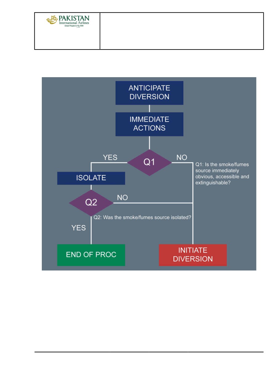
An immediate diversion should be considered as soon as the smoke/fumes are detected. If the
source is not immediately obvious, accessible and extinguishable, an immediate diversion should be
initiated without delay.
SMOKE / FUMES DETECTION AND PROCEDURE APPLICATION
Ident.: PR-AEP-SMOKE-00019270.0002001 / 15 NOV 21
Applicable to: ALL
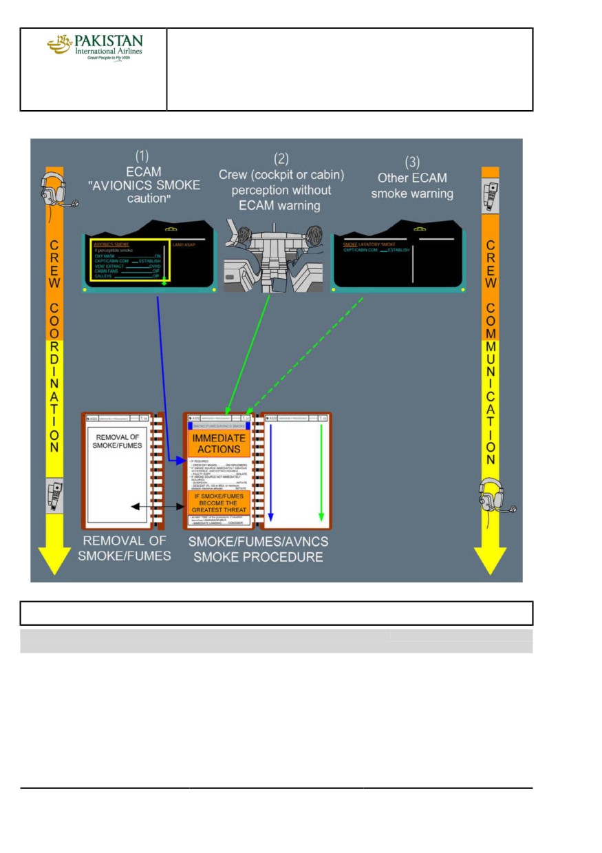
The smoke or fumes will be identified either by an ECAM alert, or by the crew without any ECAM
alert.
If the smoke or fumes are detected by the crew, without any ECAM alert, the flight crew will refer
directly to the [QRH] SMOKE / FUMES / AVNCS SMOKE procedure.
If the AVIONICS SMOKE alert is activated, the flight crew can refer directly to the [QRH] SMOKE /
FUMES / AVNCS SMOKE procedure, or apply first the ECAM actions, before entering the QRH.
The AVIONICS SMOKE alert should be applied only IF SMOKE / FUMES ARE PERCEPTIBLE.
The smoke or fumes are perceptible if the flight crew can confirm it visually or by smell.
If smoke or fumes are not perceptible, the flight crew should consider a spurious alert and therefore
stop the AVIONICS SMOKE procedure.
If another ECAM SMOKE alert (e.g. LAVATORY SMOKE) is triggered, the flight crew must apply the
ECAM procedure. If any doubt exists about the smoke/fumes origin, the flight crew will then refer to
the [QRH] SMOKE / FUMES / AVNCS SMOKE procedure.
PIA A318/A319/A320/A321 FLEET
PR-AEP-SMOKE P 1/10
FCTM
A to B →
23 NOV 21
PROCEDURES
ABNORMAL AND EMERGENCY PROCEDURES
A318/A319/A320/A321
FLIGHT CREW
SMOKE
TECHNIQUES MANUAL
Smoke / Fumes Procedure Architecture
COORDINATION WITH CABIN CREW
Ident.: PR-AEP-SMOKE-00019271.0001001 / 15 NOV 21
Applicable to: ALL
Good coordination between cockpit and cabin crew is a key element .
In case of smoke/fumes in the cabin, it is essential that the cabin crew estimate and inform the
cockpit concerning the density of smoke/fumes and the severity of the situation.
PIA A318/A319/A320/A321 FLEET
PR-AEP-SMOKE P 2/10
FCTM
← B to C
23 NOV 21
PROCEDURES
ABNORMAL AND EMERGENCY PROCEDURES
A318/A319/A320/A321
FLIGHT CREW
SMOKE
TECHNIQUES MANUAL
SMOKE / FUMES / AVNCS SMOKE QRH PROCEDURE
Ident.: PR-AEP-SMOKE-00019272.0001001 / 22 NOV 21
Applicable to: ALL
GENERAL
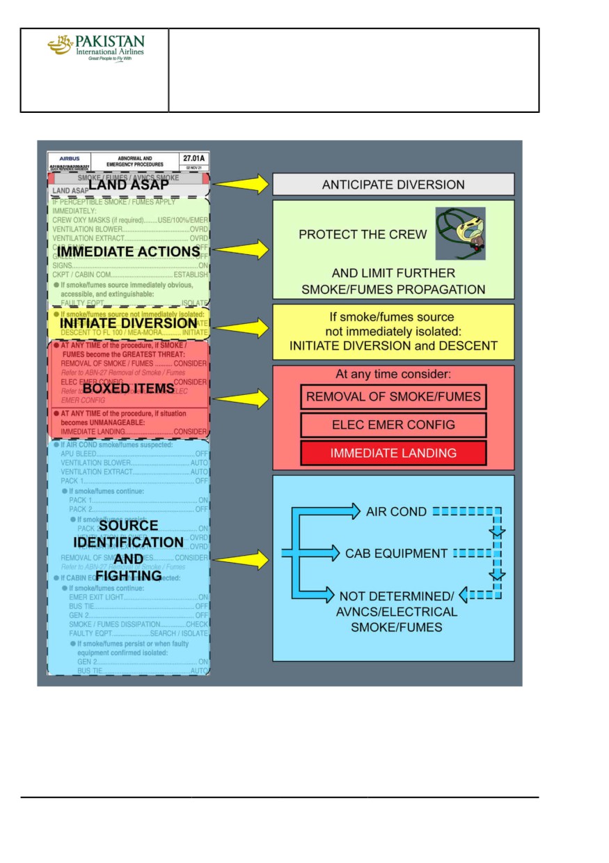
The [QRH] SMOKE / FUMES / AVNCS SMOKE procedure implements a global philosophy that is
applicable to both cabin and cockpit smoke/fumes cases. This philosophy includes the following
main steps:
- Diversion to be anticipated
- Immediate actions.
If smoke/fumes source not immediately isolated:
- Diversion initiation
- Smoke/fumes origin identification and fighting.
Furthermore, at any time during the procedure application, if smoke/fumes become the greatest
threat, the boxed items will be completed.
The main steps of this global philosophy may be visualized in the [QRH] SMOKE / FUMES /
AVNCS SMOKE procedure.
PIA A318/A319/A320/A321 FLEET
PR-AEP-SMOKE P 3/10
FCTM
D →
23 NOV 21
PROCEDURES
ABNORMAL AND EMERGENCY PROCEDURES
A318/A319/A320/A321
FLIGHT CREW
SMOKE
TECHNIQUES MANUAL
SMOKE / FUMES / AVNCS SMOKE Procedure Presentation in QRH
CONSIDERATIONS ABOUT DIVERSION
Time is critical.
Therefore, the flight crew must immediately anticipate a diversion, as indicated by LAND ASAP in
the procedure.
PIA A318/A319/A320/A321 FLEET
PR-AEP-SMOKE P 4/10
FCTM
← D →
23 NOV 21
PROCEDURES
ABNORMAL AND EMERGENCY PROCEDURES
A318/A319/A320/A321
FLIGHT CREW
SMOKE
TECHNIQUES MANUAL
Then, after the immediate actions, if the smoke/fumes source are not immediately identified and
isolated, the flight crew must initiate the diversion before entering the identification and isolation
part of the procedure.
IMMEDIATE ACTIONS
These actions are common to all cases of smoke or fumes, whatever the source.
Their objectives are:
- Flight crew protection
- Avoiding any further contamination of the cockpit/cabin
- Communication with cabin crew.
PIA A318/A319/A320/A321 FLEET
PR-AEP-SMOKE P 5/10
FCTM
← D →
23 NOV 21
PROCEDURES
ABNORMAL AND EMERGENCY PROCEDURES
A318/A319/A320/A321
FLIGHT CREW
SMOKE
TECHNIQUES MANUAL
SMOKE/FUMES ORIGIN IDENTIFICATION AND FIGHTING
The crew tries to identify the smoke/fumes source by isolating systems. Some guidelines may help
the crew to identify the origin of smoke/fumes:
- If smoke/fumes initially come out of the cockpit's ventilation outlets, or if smoke/fumes are
detected in the cabin, the crew may suspect an AIR COND SMOKE/FUMES. In addition,
very shortly thereafter, several SMOKE alerts (cargo, lavatory, avionics) will be triggered. The
displayed ECAM procedures must therefore be applied.
- Following an identified ENG or APU failure, smoke/fumes may emanate from the faulty item
through the bleed system and be perceptible in the cockpit or the cabin. In that case, it will be
re-circulated throughout the aircraft, until it completely disappears from the air conditioning
system.
- If only the AVIONICS SMOKE alert is triggered, the crew may suspect an AVIONICS SMOKE.
- If smoke/fumes are detected, while an equipment is declared faulty, the crew may suspect that
smoke/fumes are coming from this equipment.
- The crew may also perceive fumes with odors: to help the identification of the possible source
and to enhance the communication coordination with the cabin crew, the table below gathers
some of the fumes with odors that may occur on board, with the suspected causes.
SUSPECTED CAUSE
DESCRIPTION OF ODORS
(MOST REPORTED LISTED FIRST)
Electrical Equipment/IFE
Acrid
Engine Oil Leak
Electrical Equipment
Burning
Galley Equipment
Bird Ingestion
Contaminated Bleed Ducts
Chemical
APU Ingestion
Smoke Hood
Chlorine
Blocked Door Area Drain
Electrical
Electrical Equipment
Dirty Socks
APU or Engine Oil Leaks
Foul
Lavatories
Fuel
APU FCU/Fuel Line
Oil
Engine or APU Oil Leak
Skydrol
Engine Hydraulic
Wiring
Sulphur
Avionics Filter Water Contamination
Light Bulb
PIA A318/A319/A320/A321 FLEET
PR-AEP-SMOKE P 6/10
FCTM
← D →
23 NOV 21
PROCEDURES
ABNORMAL AND EMERGENCY PROCEDURES
A318/A319/A320/A321
FLIGHT CREW
SMOKE
TECHNIQUES MANUAL
According to the source he suspects, the crew will enter one of the 3 paragraphs:
1. IF AIR COND SMOKE/FUMES SUSPECTED…
2. IF CAB EQUIPMENT SMOKE/FUMES SUSPECTED…
3. IF AVNCS/COCKPIT SMOKE/FUMES SUSPECTED…
Since electrical fire is the most critical case, the flight crew will also enter paragraph 3 if the
source of the smoke/fumes is not identified, or if the application of paragraph 1 and/or 2 has been
unsuccessful.
In this part of the procedure, the flight crew must consider setting the Emergency Electrical
Configuration, to shed as much equipment as possible. This is in order to attempt to isolate the
smoke/fumes source.
If at least one battery is charging when one side and then the other side of the electrical system
are shed, the DC1, DC2, and BAT bus bars become inoperative for the remainder of the flight.
Therefore, the procedure for attempting to partially shed the electrical system was removed from
the smoke/fumes procedure. This change in the procedure is to enable the flight crew to recover
the normal electrical configuration for landing, particularly to recover normal braking.
If the flight crew sets the electrical emergency configuration following a smoke/fumes detection
in the avionic compartment (AVIONICS SMOKE alert triggered), the ECAM does not display the
same procedure as the one displayed following the loss of main generators. In fact in this case,
the ECAM displays a specific procedure that takes into account the smoke detection: As the flight
crew has voluntarily set the electrical emergency configuration, the purpose of the ELEC EMER
CONFIG procedure is not to try to restore the generators, but to remain in electrical emergency
configuration, and restore generators before landing to perform the landing in normal electrical
configuration.
BOXED ITEMS
These items (applying [QRH] REMOVAL OF SMOKE / FUMES procedure, setting electrical
emergency configuration, or considering immediate landing) may be applied at any time, in the
procedure (but not before the immediate actions).
Once the first step of the [QRH] REMOVAL OF SMOKE / FUMES procedure have been applied,
the flight crew will come back to the [QRH] SMOKE / FUMES / AVNCS SMOKE procedure, to
apply the appropriate steps, depending on the suspected smoke/fumes source while descending
to FL 100. Reaching FL 100, the [QRH] REMOVAL OF SMOKE / FUMES procedure will be
completed.
PIA A318/A319/A320/A321 FLEET
PR-AEP-SMOKE P 7/10
FCTM
← D
23 NOV 21
PROCEDURES
ABNORMAL AND EMERGENCY PROCEDURES
A318/A319/A320/A321
FLIGHT CREW
SMOKE
TECHNIQUES MANUAL
LITHIUM BATTERY FIRE IN THE COCKPIT
Ident.: PR-AEP-SMOKE-00019273.0001001 / 04 OCT 19
Applicable to: ALL
Several electronic devices contain lithium batteries, for example:
- Laptop computers,
- Mobile phones,
- Portable electronic tablets, etc.
Fire or smoke from lithium battery is due to thermal runaway in the battery cells.
It is important to know that fire extinguishers are efficient on flames but cannot stop thermal runaway.
The treatment for thermal runaway of lithium battery is to cool the battery by pouring water or
non-alcoholic liquid on the device.
The first step of the procedure establishes appropriate tasksharing and communication.
If necessary, transfer control to the flight crew member seated on the opposite side of the fire.
The Pilot Flying (PF) contacts the cabin crew to request initiation of the CCOM “STORAGE
PROCEDURE AFTER A LITHIUM BATTERY FIRE".
This CCOM procedure specifies that the cabin crew must fill a container with water or non-alcoholic
liquid and must immerse the device in it.
If there is no cabin crew on board (e.g ferry flight, etc.), the Pilot Monitoring (PM) must apply the
steps of the CCOM procedure.
If there are flames, the PM must use the fire extinguisher.
Before discharging the fire extinguisher, it is important to protect the flight crew respiratory system:
the PF must wear the oxygen mask and the PM must wear the smoke hood .
If there are no flames, or when the flames are extinguished, the PM must assess if the device can be
removed or not from the cockpit.
If the device is attached to a cable that cannot be easily disconnected, then the device must be
considered not removable from the cockpit, and water or non-alcoholic liquid must be poured on it.
The device must then be regularly monitored to ensure that the thermal runaway is successfully
stopped. If the device is removable, then it must be put in the container prepared in advance by the
cabin crew member who takes over the procedure.
If, at any time of the procedure, the smoke becomes the greatest threat, the flight crew must consider
applying the SMOKE/FUMES REMOVAL procedure.
Finally, if at any time of the procedure, the situation becomes unmanageable an immediate landing
must be considered.
PIA A318/A319/A320/A321 FLEET
PR-AEP-SMOKE P 8/10
FCTM
E
23 NOV 21
PROCEDURES
ABNORMAL AND EMERGENCY PROCEDURES
A318/A319/A320/A321
FLIGHT CREW
SMOKE
TECHNIQUES MANUAL
CARGO SMOKE
Ident.: PR-AEP-SMOKE-00019274.0001001 / 20 MAR 17
Applicable to: ALL
The crew should be aware that, even after successful operation of the cargo fire bottle, the CARGO
SMOKE warning might persist due to the smoke detectors being sensitive to the extinguishing agent.
On the ground, the crew should instruct the ground crew not to open the cargo door until the
passengers have disembarked and fire services are present.
If SMOKE warning is displayed on ground with the cargo compartment door open, do not initiate an
AGENT DISCHARGE. Request the ground crew to investigate and eliminate the smoke source. On
ground, the warning may be triggered due to a high level of humidity.
PIA A318/A319/A320/A321 FLEET
PR-AEP-SMOKE P 9/10
FCTM
F
23 NOV 21
PROCEDURES
ABNORMAL AND EMERGENCY PROCEDURES
A318/A319/A320/A321
FLIGHT CREW
SMOKE
TECHNIQUES MANUAL
Intentionally left blank
PIA A318/A319/A320/A321 FLEET
PR-AEP-SMOKE P 10/10
FCTM
23 NOV 21
PREVENTING
IDENTIFIED RISKS
Intentionally left blank
PREVENTING IDENTIFIED RISKS
PRELIMINARY PAGES
A318/A319/A320/A321
FLIGHT CREW
TABLE OF CONTENTS
TECHNIQUES MANUAL
Introduction
A
Risks related to Flight Phases
B
Risks related to System Operations/Failures
C
PIA A318/A319/A320/A321 FLEET
PIR-PLP-TOC P 1/2
FCTM
23 NOV 21
PREVENTING IDENTIFIED RISKS
PRELIMINARY PAGES
A318/A319/A320/A321
FLIGHT CREW
TABLE OF CONTENTS
TECHNIQUES MANUAL
Intentionally left blank
PIA A318/A319/A320/A321 FLEET
PIR-PLP-TOC P 2/2
FCTM
23 NOV 21
PREVENTING IDENTIFIED RISKS
A318/A319/A320/A321
FLIGHT CREW
TECHNIQUES MANUAL
INTRODUCTION
Ident.: PIR-00005742.0001001 / 19 MAY 17
Applicable to: ALL
The aim of this chapter is to highlight some of the risks and potential consequences that the flight
crew may encounter, in order to improve:
- The awareness of the flight crew with regards to these risks
- The risk management.
CATEGORY OF RISKS, AND ASSOCIATED SYMBOL
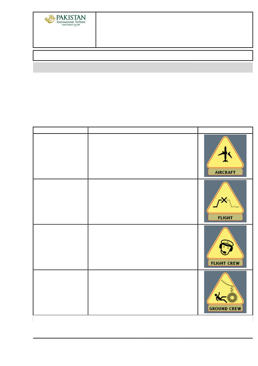
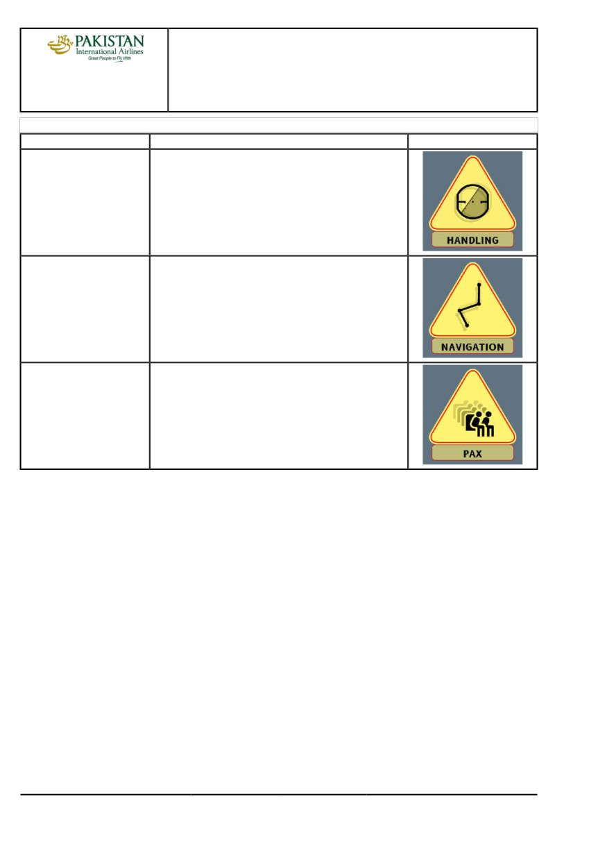
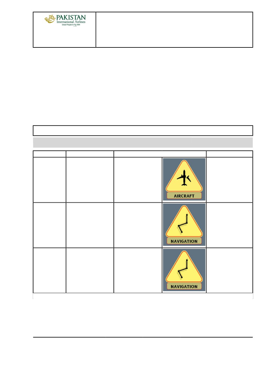
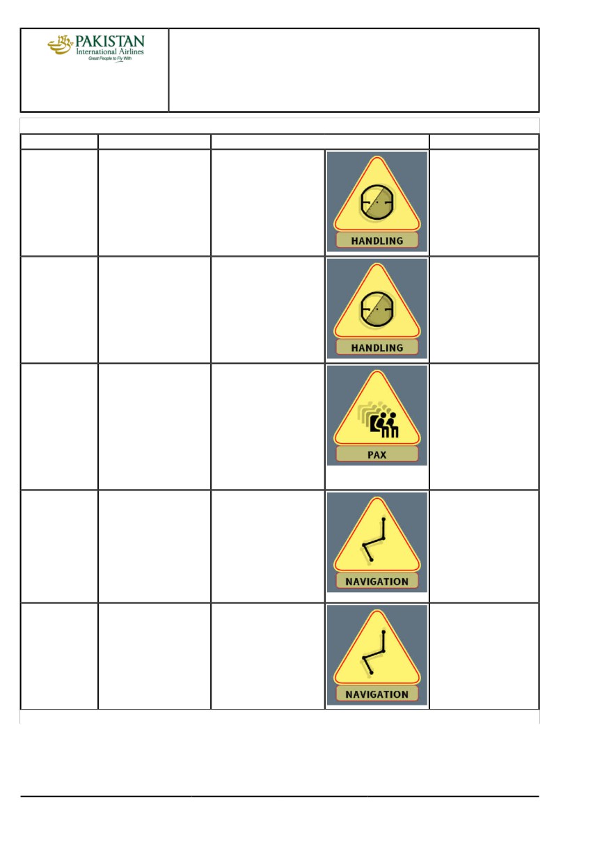
7 categories of risks may be encountered:
Categories
Potential Consequences
Symbol
AIRCRAFT
Possibility of damage to the aircraft.
FLIGHT
It may not be possible to complete the initial flight.
FLIGHT CREW
Possibility of flight crew incapacitation, or injury.
GROUND CREW
Possibility of injury to the ground personnel.
Continued on the following page
PIA A318/A319/A320/A321 FLEET
PIR P 1/10
FCTM
A →
23 NOV 21
PREVENTING IDENTIFIED RISKS
A318/A319/A320/A321
FLIGHT CREW
TECHNIQUES MANUAL
Continued from the previous page
Categories
Potential Consequences
Symbol
HANDLING
The handling or the control of the aircraft may be affected.
NAVIGATION
The navigation may be affected.
PAX
Possibility of injury to passengers.
RISKS RELATED TO FLIGHT PHASES
In normal operations, some risks may be encountered during specific flight phases.
For each risk, a dedicated table provides:
- The flight phase, where the risk may be encountered
- A description of the risk
- A description of the consequences, if the flight crew does not correctly manage the risk
- The type of the consequences of the risk (who, or what is affected) illustrated with the
appropriate risk symbol
- When applicable, a reference to the FCTM part, where the related explanations and
recommendations (for prevention and/or recovery) are developed.
Refer to PIR Risks related to Flight Phases.
RISKS RELATED TO SYSTEM OPERATIONS/FAILURES
Some risks may be encountered during the interaction of the flight crew with systems, or in the
case of system failure.
PIA A318/A319/A320/A321 FLEET
PIR P 2/10
FCTM
← A →
23 NOV 21
PREVENTING IDENTIFIED RISKS
A318/A319/A320/A321
FLIGHT CREW
TECHNIQUES MANUAL
For each risk, a dedicated table provides:
- The aircraft system related to the risk
- A description of the risk
- A description of the consequences, if the flight crew does not correctly manage the risk
- The type of the consequences of the risk (who, or what is affected) illustrated with the
appropriate risk symbol
- When applicable, a reference to the FCTM part, where the related explanations and
recommendations (for prevention and/or recovery) are developed.
Refer to PIR Risks related to System Operations/Failures.
RISKS RELATED TO FLIGHT PHASES
Ident.: PIR-00005743.0001001 / 22 NOV 21
Applicable to: ALL
Flight phase
Risk
Consequences
Refer to
Exterior
During the exterior
Refer to PR-NP-SOP-50
- In-flight loss of the fan
Walkaround
walkaround, the flight
Exterior Walkaround.
cowl doors
crew does not check
- Structural damage to
that the fan cowl doors
the aircraft
are properly closed and
- Danger to people on
latched.
ground.
Cockpit
The flight crew does not
The flight crew
Preparation
correctly adjust the outer
awareness of the weather
ring of the ND brightness
and the terrain will be
knob to the maximum.
reduced in flight.
Cockpit
The flight crew does
Erroneous trajectory.
Refer to PR-NP-SOP-60
Preparation
not check that the
FMGS Preparation.
FMS SID (including the
constraints) is correct.
Continued on the following page
PIA A318/A319/A320/A321 FLEET
PIR P 3/10
FCTM
← A to B →
23 NOV 21
PREVENTING IDENTIFIED RISKS
A318/A319/A320/A321
FLIGHT CREW
TECHNIQUES MANUAL
Continued from the previous page
Flight phase
Risk
Consequences
Refer to
Takeoff
The flight crew
Engine check not valid.
Refer to
announces “THRUST
PR-NP-SOP-120
SET” before the thrust
Takeoff Roll.
reaches the target thrust
value.
Climb/Descent
The flight crew uses the
Climb or descent does
V/S knob without setting
not stop.
a target.
Descent
During descent
If the QNH is not
Refer to FCOM DSC
Preparation
preparation, the flight
correct, the CPC
22-20-50-10 PERF
crew does not properly
computes erroneous
APPR Page.
insert/check the QNH,
cabin pressurization
TEMP or BARO in the
segment, that may trigger
PERF APPR page.
pressurization related
ECAM alert and lead
to undue emergency
descent.
Descent
In managed descent,
The autothrust increases
Refer to
the flight crew uses
thrust to remain on the
PR-NP-SOP-170
the speed brakes in
computed profile. The
Guidance and
an attempt to descend
expected increased rate
Monitoring.
below the computed
of descent will not be
profile.
reached. In addition,
fuel consumption will
increase.
Descent
The flight crew does not
Reduced situational
set the TERR ON ND
awareness.
sw to ON. In addition,
the flight crew does
not correctly adjust the
brightness.
Continued on the following page
PIA A318/A319/A320/A321 FLEET
PIR P 4/10
FCTM
← B →
23 NOV 21
PREVENTING IDENTIFIED RISKS
A318/A319/A320/A321
FLIGHT CREW
TECHNIQUES MANUAL
Continued from the previous page
Flight phase
Risk
Consequences
Refer to
Approach
One flight crewmember
The other flight
Refer to PR-NP-GEN
activates the approach
crewmember may
Communication.
phase without
perceive the speed
crosschecking with the
change as abnormal, and
other one.
may react to it.
Approach
The flight crew uses
NAV mode arms. If NAV
Refer to
DIR TO or DIR TO
mode is not appropriate,
PR-NP-SOP-190-CONF
RAD IN functions to
it may lead to an
F-PLN Sequencing.
sequence the F-PLN,
erroneous trajectory.
and the aircraft is in radar
vectoring.
Approach
The flight crew does not
Any erroneous
sufficiently monitor raw
computation leads to an
data.
erroneous trajectory.
ILS Approach
The glide slope is
The aircraft descends
Refer to
intercepted from above
through the glide slope,
PR-NP-SOP-190-GUI
and the G/S mode is not
without intercepting it.
Glide Slope Interception
armed.
from Above.
Continued on the following page
PIA A318/A319/A320/A321 FLEET
PIR P 5/10
FCTM
← B →
23 NOV 21
PREVENTING IDENTIFIED RISKS
A318/A319/A320/A321
FLIGHT CREW
TECHNIQUES MANUAL
Continued from the previous page
Flight phase
Risk
Consequences
Refer to
Non Precision
When the aircraft
The AP may not
Approach
reaches the minimum
disconnect until landing
height for use of AP, the
and autoland is not
flight crew does not set
provided on NPA.
the AP to OFF.
Go Around
When the flight crew
The SRS GA mode and
Refer to
initiates the go-around,
the FMS go-around
PR-NP-SOP-260 AP/FD
the PF does not set the
phase do not engage.
Go-Around Phase
thrust levers to the TOGA
Therefore, the AP/FD
Activation.
detent or the FLAPS
remain engaged in
lever is at 0.
approach, or landing
mode and the FMS
remains in APPR phase.
RISKS RELATED TO SYSTEM OPERATIONS/FAILURES
Ident.: PIR-00005745.0001001 / 04 NOV 20
Applicable to: ALL
Aircraft System
Risk
Consequences
Refer to FCTM
Auto Flight
In order to disconnect the
Immediate and undue
Refer to AS-FG-10-2 To
autothrust, the flight crew
thrust increase.
Set Autothrust To Off
presses the instinctive
disconnect pb on the
thrust levers before they
move the thrust levers to
the current thrust setting.
Auto Flight
The flight crew does not
TOGA thrust is
Refer to AS-FG-10-2 To
disconnect the autothrust
maintained, with an
Set Autothrust To Off
when Alpha floor/TOGA
undue thrust increase,
LOCK triggers.
and may lead to
overspeed.
Continued on the following page
PIA A318/A319/A320/A321 FLEET
PIR P 6/10
FCTM
← B to C →
23 NOV 21
PREVENTING IDENTIFIED RISKS
A318/A319/A320/A321
FLIGHT CREW
TECHNIQUES MANUAL
Continued from the previous page
Aircraft System
Risk
Consequences
Refer to FCTM
Auto Flight
The flight crew does not
Trajectory not correct.
use the correct knob
to change heading or
speed.
Auto Flight
The flight crew does not
Erroneous computation
Refer to
sequence the F/PLN.
(e.g. time, fuel) and
PR-NP-SOP-190-CONF
trajectory.
F-PLN Sequencing
Communications
Error in the use of RMP.
Loss of transmission to
ATC due to an erroneous
setting.
Engines
In the case of an engine
Performing the ECAM
Refer to PR-AEP-ENG
failure after takeoff, the
actions before the aircraft
Engine Failure after V1
flight crew does not
is stabilized on the flight
stabilize the flight path
path, reduces efficiency
before they perform
due to the PF’s high
ECAM actions.
workload, and may lead
to a trajectory error.
Engines
In the case of an engine
Pressing the EO CLR
Refer to PR-AEP-ENG
failure in cruise, the flight
key on the MCDU is an
Engine Failure During
crew presses the EO
irreversible action that
Cruise
CLR key on the MCDU.
leads to the loss of single
engine computation
(discrepancy between
the computation and real
aircraft status).
Continued on the following page
PIA A318/A319/A320/A321 FLEET
PIR P 7/10
FCTM
← C →
23 NOV 21

PREVENTING IDENTIFIED RISKS
A318/A319/A320/A321
FLIGHT CREW
TECHNIQUES MANUAL
Continued from the previous page
Aircraft System
Risk
Consequences
Refer to FCTM
Flight Controls
The flight crew does not
At takeoff:
Refer to PR-AEP-F_CTL
select the speed after slat
When slats/flaps are
Abnormal Flaps/Slats
or flap failure.
locked and if the flight
Configuration
crew does not select the
current speed, the aircraft
continues to accelerate
and possibly exceeds
Max Speed.
In approach:
When slats/flaps are
locked and if the flight
crew does not select the
current speed, the aircraft
continues to decelerate
down to a speed that
is not consistent with
the current aircraft
configuration.
Flight Controls -
In the case of flight with
Erroneous computation
Refer to PR-AEP-F_CTL
Landing Gear
slats/flaps extended or
(e.g. time, fuel), because
Abnormal Flaps/Slats
landing gear extended,
the FMS does not take
Configuration
the flight crew takes
into account the abnormal
into account the FMS
configuration.
predictions.
Fuel
The flight crew does not
Fuel loss.
Refer to PR-AEP-FUEL
check fuel before fuel
Fuel Leak
crossfeed.
Miscellaneous
For EMERGENCY
The flight crew does not
Refer to PR-AEP-MISC
DESCENT, the flight crew
detect that the descent
EMER DESCENT
turns but does not pull the
is not engaged. Delayed
ALT knob, or does both,
descent leads to limited
but not in the correct
oxygen for passengers.
sequence, with no FMA
crosscheck.
Continued on the following page
PIA A318/A319/A320/A321 FLEET
PIR P 8/10
FCTM
← C →
23 NOV 21
PREVENTING IDENTIFIED RISKS
A318/A319/A320/A321
FLIGHT CREW
TECHNIQUES MANUAL
Continued from the previous page
Aircraft System
Risk
Consequences
Refer to FCTM
Navigation
In order to set the ADR to
Irreversible loss of NAV
Refer to PR-AEP-NAV
OFF, the flight crew use
mode of the associated
ADR/IRS FAULT
the IR MODE selector
IR for the remainder of
instead of the ADR
the flight (the position
pb-sw.
LAT / LONG is lost).
Flight crew can recover
only the ATT mode of the
associated IR.
Surveillance
The flight crew performs
The autothrust mode
Refer to AS-TCAS
the TCAS resolution
may remain in THR CLB
TCAS
advisory procedure
or THR IDLE, whereas
without switching OFF the
it must be in SPEED
FDs for aircraft not fitted
mode. This may lead to
with the AP/FD TCAS, or
the activation of the high
when the AP/FD TCAS
speed/AOA protection.
function is failed.
PIA A318/A319/A320/A321 FLEET
PIR P 9/10
FCTM
← C
23 NOV 21
PREVENTING IDENTIFIED RISKS
A318/A319/A320/A321
FLIGHT CREW
TECHNIQUES MANUAL
Intentionally left blank
PIA A318/A319/A320/A321 FLEET
PIR P 10/10
FCTM
23 NOV 21
Aerosoft
The Airbus A318/319/320/321 in FSX
Vol
06-01-07 Page 1
Airbus A318/319/320/321
Step-By-Step Tutorial
6
07 April 2015
Aerosoft Airbus
A318/319/320/321
Volume 6
Step By Step Tutorial
Rolf Fritze
Version 06-01-07
RECORD OF REVISIONS
Revision no
Issue date
Description
no
01-01
19/09/2014
First issue
IAE behavior during startup added (#98 and 112) / Call #162 / Picture 67 / as well as chapter
01-02
22/09/2014
5.22 (FL change) changed
01-03
25/09/2014
Various changes based on pilot, developer and user feedback
#48 ATIS frequency, #148 start conditions, #234 start APPR CL, picture #22 LOAD-/FUEL
01-04
15/10/2014
PLANNER changed, #283 and 284 added, #59 changed, 4.6.5 und 4.6.6 = TILLER option added,
EXT Lights adjusted and STEEP APPROACH SOP added
Pause before T/D: Distance changed to 20 NM (chapter 4.6.5)
GO AROUND procedure modified (chapter 5.23)
01-05
09/11/2014
COG Calculation / THS aligned with VC Trim Scale and Fuelplanner (#59)
A320/321 added to document
01-06
16/11/2014
#89 Pushback details added, 4.7 limits added
WXR - Turbulences added (2.1.3)
Save and Load a flight (3.5)
MCDU - AIRCRAFT USER STATES: Deleted from MCDU2 menu (4.3)
Ground Crew Sound/Calls: Volume to menu added (4.6.1)
MCDU Menu - define FS - P3D Infobar set lower (4.6.2)
CL Config Menü AES Pusback ON/OFF and Infobar: GSX added (4.6.3)
AES/GSX und AFTER START CL: Timing aligned (4.6.3)
01-07
07/04/2015
Connected Flight Deck (4.9)
Pushback: Distance set to minimum value = 9m (5.7.1 #89)
ECAM Instruction - BRAKE TOO HOT: Values changed to 150/100° (5.10 #149)
Explanations for the use of speedbrakes (5.21 #253)
Use of 2nd Autopilot (5.21 - #256)
Appr. Speed Restr. FINAL CL - Landing Memo - <160 kts added as condition 5.21 #259a)
VECTOR APPROACH and use of DIR TO / RADIAL IN for tutorial flight (6.)
Aerosoft
The Airbus A318/319/320/321 in FSX
Vol
06-01-07 Page 2
Airbus A318/319/320/321
Step-By-Step Tutorial
6
07 April 2015
Table of Content
Chapter
Content
Page
1.
Start FSX-Settings
7
1.1
Start FSX
7
1.2
General FSX Settings
7
1.3
Simulation Rate / Time Compression
7
2.
Panels and Instruments
8
2.1.
Glareshield and Main Panel
10
2.1.1
PFD - Primary Flight Display / ISIS
11
2.1.2
ND - Navigations Display (Standard)
11
2.1.3
ND - Navigations Display (WXR - Weather Radar))
12
2.1.4
ND - Navigations Display (EGPWS - Terrain on ND))
16
2.1.5
EFIS - Electronic Flight Information System
17
2.1.6
FCU - Flight Control Unit
17
2.1.7
E/WD - Engine- / Warning-Display
18
2.2
Overhead Panel
19
2.3
FMGC - MCDU - Multifunctional Control and Display Unit
20
2.4
ECAM - Electronic Centralized Aircraft Monitoring
20
2.5
Pedestal
21
3.
General Information / Tips
22
3.1
Additional Information
22
3.2
Pictures
22
3.3
Procedure- and Checklist
22
3.4
Switching ON and OFF function- changing values
22
3.5
Saving a certain flight and aircraft state
22
3.6
Saving Flight Plans
23
3.7
Sound (background)
23
3.8
Tutorial Flight with Aerosoft A319 CFM
23
4.
Flight Preparation
25
4.1
Fuel and Payload Planning
25
4.2
Calculation of Takeoff Performance Data
26
4.3
MCDU 2 Menu - Aircraft State
26
4.4
MCDU 2 Menu - Aircraft Doors
27
4.5
MCDU 2 Menu - Ground Services
28
4.6
MCDU 2 Menu - Options
28
4.6.1
Options - Sound
29
4.6.2
Options - Views
39
4.6.3
Options - Checklists
32
4.6.4
Options - Flight Data Recorder
34
4.6.5
Options - Flight
35
4.6.6
Options - Aircraft
36
4.7
MCDU 2 Menu - Load / Fuel
36
4.8
MCDU 2 Menu - Checklists
38
4.9
Connected Flight Deck
39
4.10
Voice packs for PF and PM
39
4.11
Saving all settings
40
4.12
RAAS - Runway Alert and Advisory System
40
5.
Tutorial Flight / Checklists and Procedures
41
5.1
Basic Information - Setup
41
5.2
Basic Preparation Procedure
41
5.3
Cockpit Preparation - Part 1
42
5.4
FMGS / MCDU - Data Insertion
43
5.5
Cockpit Preparation - Part 2
46
5.6
Before Pushback and Start
47
5.7
Engine Start
47
5.7.1
Engine Start with Pushback
48
5.7.2
Engine Start
49
5.8
After Engine Start
49
Aerosoft
The Airbus A318/319/320/321 in FSX
Vol
06-01-07 Page 3
Airbus A318/319/320/321
Step-By-Step Tutorial
6
07 April 2015
5.9
Taxi
50
5.10
Before Takeoff
51
5.11
Takeoff (Part 1)
51
5.12
Abort Takeoff
52
5.13
Takeoff (Part 2)
52
5.14
After Takeoff
54
5.15.
Climb
55
5.16
Cruise
56
5.17
MCDU PERF APPR Page
56
5.18
Descent Preparation
58
5.19
Descent
59
5.20
ILS-Approach
60
5.21
Final
62
5.22
Landing
67
5.23
Go Around
68
5.24
After Landing
72
5.25
Parking
72
5.26
Secure Aircraft
73
6.
Vector Approach using DIR TO and RADIAL IN
74
7.
Non Precision Approach
80
7.1
Introduction
80
7.2
Settings / Flightplan for Tutorial
81
7.3
Weather LGKR
81
7.4
Checklist- and Copilot Function
81
7.5
Charts used for this NPA at LGKR RWY 35
81
7.6
Approach Brief
83
7.7
Required PFD Symbology Knowledge
83
7.8
Descent Preparation and Descent
84
7.9
Initial Approach Fix (IAF)
85
7.10
Deceleration Point
86
7.11
Final Approach Fix (FAF)
88
7.12
Minimum Decision Altitude (MDA)
89
7.13
Summary
89
8.
A318 - STEEP APPROACH
90
8.1
Introduction
90
8.2
Settings / Flightplan
90
8.3
Weather EGLC
90
8.4
Checklist- and Copilot Function
90
8.5
Flight Path and charts
90
8.6
MCDU PERF APPR PAGE
92
8.7
Descent Preparation
93
8.8
Descent
94
8.9
Approach
96
8.10
Final
97
8.11
Landing
101
9.
Alternate Company Routes and Destinations
103
9.1
Alternate Company Routes
103
9.2
Alternate Destinations
106
10.
Tips and Tricks
110
10.1
Adjusting Views
110
10.2
Keeping / Saving adjusted views
110
10.3
Working with real flight plans
110
10.4
“Capturing” the ILS Glide Path
110
10.5
Transfer document to iPad
111
10.6
MCDU (left) on an external device
111
10.7
Use of Procedure- and Checklist
111
10.8
Manually entered Waypoints
111
11.
Appendix - Glossary
112
12.
Appendix - Procedure- and Checklist A318/319/320 and 321
115
Aerosoft
The Airbus A318/319/320/321 in FSX
Vol
06-01-07 Page 4
Airbus A318/319/320/321
Step-By-Step Tutorial
6
07 April 2015
PICTURE
1: DEFAULT VC VIEW, SELECTED WITH THE [S] KEY AND WHERE NEEDED CYCLED TO THIS VIEW WITH THE [A] KEY
8
PICTURE
2: MAIN PANEL AND GLARESHIELD VIEW (SIMILAR TO A 2D PANEL) SELECTED WITH [F9]
8
PICTURE
3: ECAM AND UPPER PEDESTAL VIEW, SELECTED WITH [F10]
9
PICTURE
4: PEDESTAL VIEW, SELECTED WITH [F11]
9
PICTURE
5: OVERHEAD VIEW, SELECTED WITH [F12]
9
PICTURE
6: GLARESHIELD AND MAIN PANEL (F9)
10
PICTURE
7: PFD - PRIMARY FLIGHT DISPLAY / ISIS
11
PICTURE
8: ND - NAVIGATION DISPLAY (STANDARD)
11
PICTURE
9: ND - SYMBOLS
12
PICTURE
10: ND - NAVIGATION DISPLAY (WXR)
12
PICTURE
11: WXR - REFLECTIVITY
13
PICTURE
12: WXR-PANEL (PEDESTAL 2.5. # 11)
13
PICTURE
13: ND - NAVIGATION DISPLAY (TURBULENCES -MAGENTA - )
16
PICTURE
14: ND - NAVIGATION DISPLAY (TAKEOFF AT LOWI 08)
16
PICTURE
15: EFIS - ELECTRONIC FLIGHT INFORMATION SYSTEM
17
PICTURE
16: FCU - FLIGHT CONTROL UNIT
17
PICTURE
17: E/WD-ENGINE WARNING DISPLAY WITH IAE / RESP. PLANE WITH CFM ENGINES
18
PICTURE
18: OVERHEAD PANEL (F12)
19
PICTURE
20: ECAM (F10)
20
PICTURE
19: MCDU (SHIFT+2)
20
PICTURE
21: PEDESTAL (F11)
21
PICTURE
22: FLIGHTPATH INNSBRUCK (LOWI) TO NICE (LFMN)
23
PICTURE
23: AIRBUS A318/319/320/321 FUEL PLANNER (ADVANCED PLANNING MODE)
25
PICTURE
24: TOTAL WEIGHT SETTINGS IN LOAD-MANAGER
26
PICTURE
25: AIRCRAFT STATE MENU
26
PICTURE
26: AIRCRAFT DOORS MENU
27
PICTURE
27: GROUND SERVICES
28
PICTURE
28: OPTIONS MENU
28
PICTURE
29: SOUNDS CONFIGURATION MENU
29
PICTURE
30: VOLUME CONFIGURATION MENU
29
PICTURE
31: VIEW CONFIGURATION MENU
30
PICTURE
32: VC PANEL BAR (DAY AND NIGHT VERSION)
30
PICTURE
33:
2D PANEL BAR (DAY AND NIGHT VERSION)
31
PICTURE
34: VERTICAL PANEL BAR
31
PICTURE
35: HORIZONTAL PANEL BAR
31
PICTURE
36: WING VIEW BAR
31
PICTURE
37: CHECKLISTS CONFIGURATION MENU
32
PICTURE
38: INFO BAR
33
PICTURE
39: FLIGHT DATA RECORDER
34
PICTURE
40: FLIGHT DATA RECORDER MENU
34
PICTURE
41: FLIGHT DATA RECORDER - DETAILS -
34
PICTURE
42: FLIGHT DATA RECORDER - RESULT IN GOOGLE EARTH -
35
PICTURE
43: FLIGHT OPTIONS
35
PICTURE
44: AIRCRAFT OPTIONS
36
PICTURE
45: LOAD/FUEL OPTIONS
36
PICTURE
46: LOAD/FUEL MENU AFTER INIT LOADSHEET
37
PICTURE
47: LOAD/FUEL MENU AFTER LOADING COMPLETED
38
PICTURE
48: CHECKLISTS MENU (PAGE A)
38
PICTURE
49: CONNECTED FLIGHT DECK MENU
39
PICTURE
51: DETAILED FLIGHT PLAN LOWI - LFMN
45
PICTURE
50: TABLE COST INDEX
44
PICTURE
52: CG (CENTRE OF GRAVITY)/ THS
46
PICTURE
53: PUSHBACK GAUGE
48
PICTURE
54: ND - ON THE RUNWAY - READY FOR TAKEOFF
51
PICTURE
55: THRUST LEVER POSITIONS
52
PICTURE
56: JOYSTICK: ON THE RUNWAY (ATTITUDE INDICATOR)
53
PICTURE
57: FLIGHT DIRECTOR: DURING TAKEOFF
53
PICTURE
58: LOWI - RUNWAY 08 - SID RTT2J
54
PICTURE
59: LOWI - RUNWAY 08 - CLIMB PROFILE
55
PICTURE
60:
10.000 FEET
55
PICTURE
61: T/C - TOP OF CLIMB = 31.000 FEET
56
Aerosoft
The Airbus A318/319/320/321 in FSX
Vol
06-01-07 Page 5
Airbus A318/319/320/321
Step-By-Step Tutorial
6
07 April 2015
PICTURE
62: MCDU - PERF - APPR PAGE (A319 AND A320)
57
PICTURE
63: LFMN ILS04L - CHART STAR „BORDI“ / TRANS “NER S”
58
PICTURE
64: TOP OF DESCENT - INITIATE DESCENT
59
PICTURE
65: ND: DECELERATION POINT
59
PICTURE
66: CHART TRANS NERAS
61
PICTURE
67: CHART ILS 04L NICE
61
PICTURE
68: FINAL PROCEDURE - ILS APPROACH PROFILE LFMN04L
62
PICTURE
69: SPEEDS “GREEN DOT”, S, F AND VAPP ON PFD
62
PICTURE
70: DECELERATION POINT
63
PICTURE
71: LOC INITIATED NEAR NI17
64
PICTURE
72: LOC CAPTURED
64
PICTURE
73: PFD - GLIDESCOPE CAPTURED - VERTICAL AND LATERAL GLIDE PATH
65
PICTURE
74: ND - ILS VIEW LFMN RWY 04L
66
PICTURE
75: ND - G/A FLIGHT PATH FOR LFMN ILS04L
69
PICTURE
76: MCDU - F-PLAN - ENTERING A HOLDING AT NERAS
70
PICTURE
77: AFTER ENTERING A HOLDING AT NERAS
70
PICTURE
78: AFTER ENTERING VIA NERAS FOR NEW APPROACH
70
PICTURE
79: AFTER DELETING F-PLAN DISCONTINUITY
71
PICTURE
80: AFTER EXIT THE HOLDING
71
PICTURE
81: ND - AFTER ACTIVATING FLIGHT PATH FOR ANOTHER ATTEMPT
71
PICTURE
82: OVERHEAD PANEL BEFORE SWITCHING OFF BOTH BATTERIES
74
PICTURE
83: VECTOR APPROACH FLIGHT PATH INTO LFMN
74
PICTURE
84: MCDU PERF APPR PAGE
75
PICTURE
85: START OF DESC PREP CL
75
PICTURE
86: REACHING NEW FL170 BEFORE BORDI
76
PICTURE
87: ND AFTER ENTERING PIRAM AS DIR TO
76
PICTURE
88: ND AFTER PASSING PIRAM
77
PICTURE
89: SELECTING DIR TO AND RADIAL IN
77
PICTURE
90: ND FLIGHT PATH AFTER DIR TO AND RADIAL IN
77
PICTURE
91: ND FLIGHT PATH BEFORE CHANGING HDG 350°
78
PICTURE
92: ND FLIGHT PATH AFTER CHANGING HDG 350°
78
PICTURE
93: ND FLIGHT PATH AFTER ARMING APPR MODE
78
PICTURE
94: APPROACHING RADIAL IN
79
PICTURE
95: FINAL APPROACH FLIGHT PATH
79
PICTURE
96: STAR CHART (PITAS2J) FOR LGKR
82
PICTURE
97: RWY35-Y VOR CHART FOR LGKR
82
PICTURE
98: VERTICAL INFORMATION FOR RWY35-Y FOR LGKR
83
PICTURE
99: FLIGHT PATH VECTOR AND FLIGHT PATH DIRECTOR 1
83
PICTURE
100: FLIGHT PATH VECTOR AND FLIGHT PATH DIRECTOR 2
84
PICTURE
101: MCDU PERF APPR PAGE
84
PICTURE
102: TOP OF DESCENT
84
PICTURE
103: DESCENT FLIGHT PATH
85
PICTURE
104: AFTER PASSING 10.000 FEET = IAF
86
PICTURE
105: DECELERATION POINT
86
PICTURE
106: FINAL APP ACTIVATED AFTER PASSING DECEL POINT
87
PICTURE
107: PASSING DIREX - DIRECTION GAR09 AND LGKR VOR 35-Y
87
PICTURE
108: BEFORE FAF = GAR09
88
PICTURE
109: PASSING GAR09 = FAF
88
PICTURE
110: MANUAL APPROACH AFTER PASSING MDA (ND = ARC MODE)
89
PICTURE
111: FLIGHT PATH EDDH - EGLC
91
PICTURE
112: STAR CHART (SPEA1B) FOR EGLC
91
PICTURE
113: MCDU PERF APPR PAGE
92
PICTURE
114: OVERHEAD PANEL AND STEEP APPR BUTTON
93
PICTURE
115: UPPER ECAM - STEEP APPROACH BUTTON = ON
94
PICTURE
116: TOP OF DESCENT - INITIATE DESCENT
95
PICTURE
117: ND: DECELERATION POINT
95
PICTURE
118: SETTINGS FOR ND MODE AND RANGE
95
PICTURE
119: DESCENT PROFILE FOR RWY ILS27 INTO LGLC
96
PICTURE
120: DECEL POINT
97
PICTURE
121: DECELERATION POINT
99
PICTURE
122: FINAL FLIGHT PATH
99
Aerosoft
The Airbus A318/319/320/321 in FSX
Vol
06-01-07 Page 6
Airbus A318/319/320/321
Step-By-Step Tutorial
6
07 April 2015
PICTURE 123: LANDING MEMO - STEEP APPROACH
100
PICTURE 124: G/S CAPTURED - LS VIEW
101
PICTURE 125: ENTERING ALTN DESTINATION - STEP 1
103
PICTURE 126: ENTERING ALTN DESTINATION - STEP 2
103
PICTURE 127: ENTERING ALTN DESTINATION - STEP 3
104
PICTURE 128: ENABLING ALTN DEST - STEP 1
104
PICTURE 129: ENABLING ALTN DEST - STEP 2
104
PICTURE 130: ENABLING ALTN DEST - STEP 3
105
PICTURE 131: ENTERING NERDU AS NEXT WPT AFTER THE REVISE POINT ALMER
105
PICTURE 132: TEMPORARY FLIGHT PLAN AFTER ENABLING ALTN
105
PICTURE 133: TEMPORARY F-PLAN AFTER MATCHING WITH ALT RTE
106
PICTURE 134: PRIMARY F-PLAN
106
PICTURE 135: ENTERING ALTN DEST = LOWW
106
PICTURE 136: NOT USING EXISTING CO RTE
107
PICTURE 137: INIT A PAGE WITH ALTN DESTINATION
107
PICTURE 138: ENABLING ALTN DEST - STEP 1
107
PICTURE 139: ENABLING ALTN DEST - STEP 2
108
PICTURE 140: ENABLING ALTN DEST - STEP 3
108
PICTURE 141: ACTIVE FLIGHT PLAN AFTER ENABLING ALTN
108
PICTURE 142: LOWW ARRIVAL
109
PICTURE 143: ACTIVE F-PLAN (BEFORE CLR)
109
PICTURE 144: ACTIVE F-PLAN EDDF - LOWW
109
PICTURE 145: ANGLE „CAPTURING“ A GLIDE PATH
110
PICTURE 146: MANUALLY ENTERED WAYPOINTS
111
Aerosoft
The Airbus A318/319/320/321 in FSX
Vol
06-01-07 Page 7
Airbus A318/319/320/321
Step-By-Step Tutorial
6
07 April 2015
1.
Start - FSX-Settings
1.1
Start FSX
Start the FSX with a “FREE FLIGHT” and use the following options:
Aircraft:
Aerosoft Airbus A319-112 CFM or IAE (any airline)
Weather:
Fair weather
Location:
Innsbruck/Austria (LOWI) at Parking 5 - RAMP GA LARGE
Time and Season:
Day - any season
The difference between CFM and IAE types are the engines built by different manufacturers.
Do NOT use default ATC and disable AI traffic. The reasons being are that ATC/AI can use different runways
than we use in our tutorial. This might end up
LOWI - Departure Airport: AI may use 26 for approaches, causing immediate TA's and RA's on takeoff.
LFMN - Arrival Airport: Apparently default ATC and AI use the opposing runway 22R.
If the aircraft it is not in the “COLD DARK” state when you load it (maybe you already set a DEFAULT aircraft
state - see chapter 4.3 for details), please set all knobs, switches and buttons to OFF so that no lights are ON
(Batteries 1 + 2 should be set OFF last) - please see chapter 5.26: Overhead Panel -. But the easiest way to
make those settings (and necessary for this tutorial flight) is to use the ACFT STATE function of the right MCDU
and set the aircraft state to “COLD DARK” (please see chapter 4.3 for details).
1.2
General FSX Settings
Adjust the FSX settings according to the Volume 1 (Vol1-InFSX EN) of the Aerosoft Airbus A318/319/320/321
documentation (chapter FSX Settings) which you will find in the FSX-folder under Aerosoft /Airbus318_A319 /
Documentation / or Aerosoft /Airbus320_A321 / Documentation /
1.3
Simulation Rate / Time Compression:
Especially during longer flights the simulation rate in the FSX Options Menu is often speeded up from normal
in order to shorten the flight. We recommend that you do not do this, as it can cause problems. This is because
the flight avionics of Airbus 318/319/320/321 are completely reprogrammed and do not use any FSX standard
features. This means that the avionics are not compatible with the time compression features of FSX.
Additionally it is depending on the performance of your computer. In the meantime we got the experience
that “time compression” works perfectly on some high-end machines.
Aerosoft
The Airbus A318/319/320/321 in FSX
Vol
06-01-07 Page 8
Airbus A318/319/320/321
Step-By-Step Tutorial
6
07 April 2015
2. Panels and Instruments:
In the following paragraph the various panel and cockpit views are explained together with the terms used in
the tutorial, this will enable the user to find the knobs, switches and buttons that the tutorial refers to. They are
the Glareshield, Main Panel, MCDU, ECAM, Pedestal/Radio and the Overhead Panel.
The Aerosoft Airbus A318/319/320/321 does not have a 2D panel - only a virtual cockpit, therefore to make it
easier to use ,6 fixed virtual 2D cockpit views have been created. These views can be accessed using three
different methods.
FSX Menu: Views - View Mode - Cockpit - ͙͙..
Keyboard: F9 = Glareshield - Main Panel, F10 = ECAM / left and right MCDU, F11 = Pedestal / Radio and
F12 = Overhead.
Keyboard: F9 = Glareshield - Main Panel and then use the [A] key to toggle between the various views
like left MCDU, right MCDU, etc.
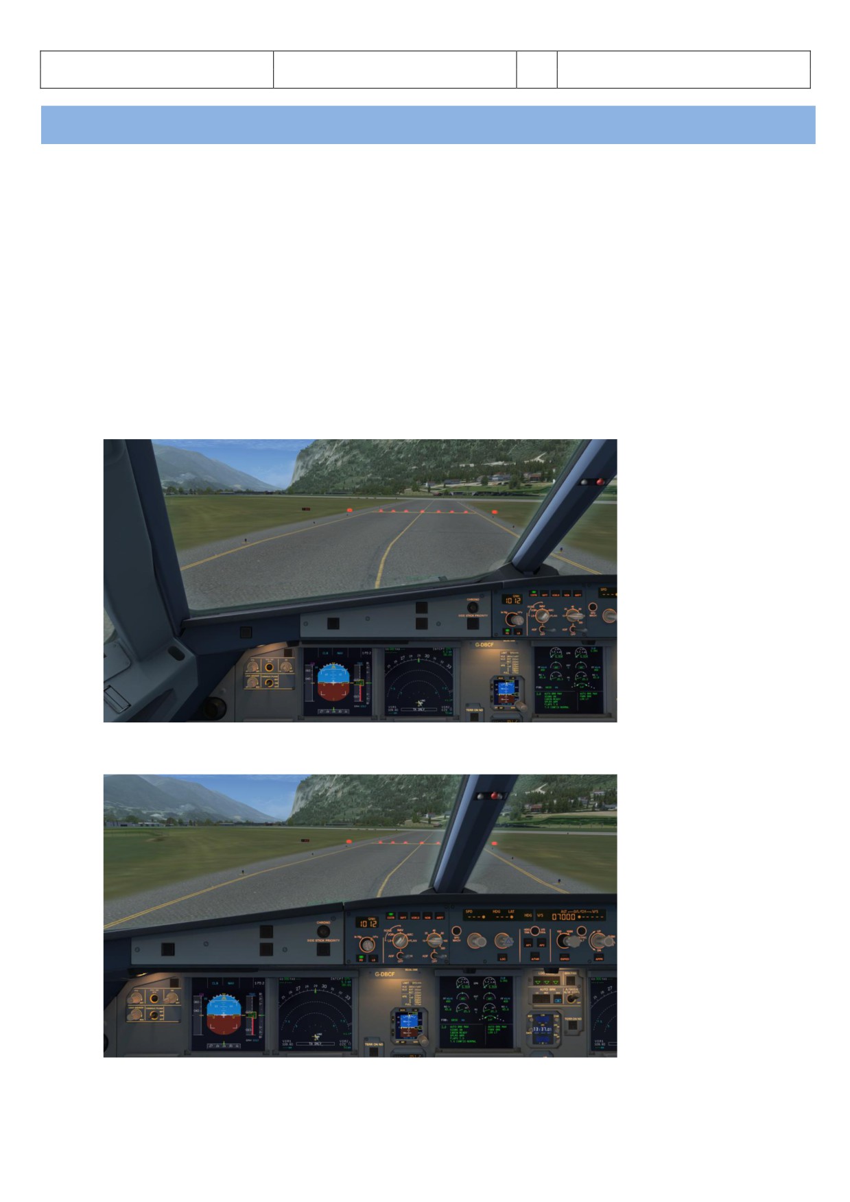
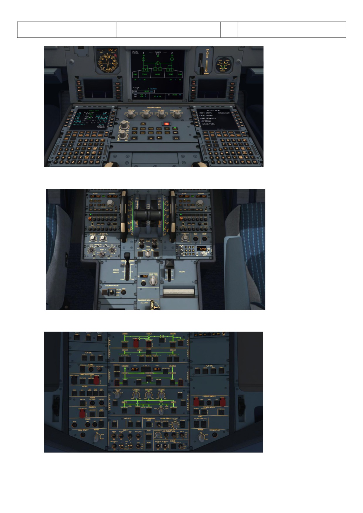
Picture 1: Default VC view, selected with the [S] key and where needed cycled to this view with the [A] key.
Picture 2: Main Panel and Glareshield View (similar to a 2D panel) selected with [F9]
Aerosoft
The Airbus A318/319/320/321 in FSX
Vol
06-01-07 Page 9
Airbus A318/319/320/321
Step-By-Step Tutorial
6
07 April 2015
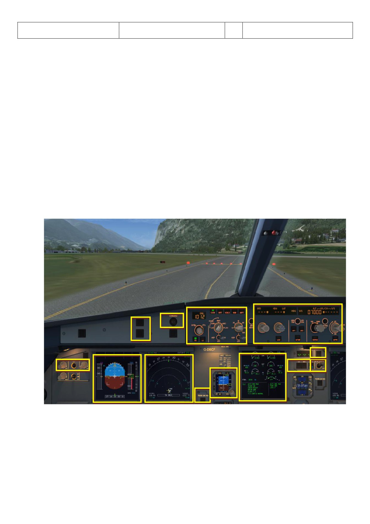
Picture 3: ECAM and Upper Pedestal view, selected with [F10]
Picture 4: Pedestal view, selected with [F11]
Picture 5: Overhead view, selected with [F12]
Aerosoft
The Airbus A318/319/320/321 in FSX
Vol
06-01-07 Page 10
Airbus A318/319/320/321
Step-By-Step Tutorial
6
07 April 2015
There is also a Panelbar available which allows you to get fast access to a lot of other fixed predefined views -
please see chapter 4.6 (OPTIONS).
Using the various keyboard combinations (please see details below) all views can be changed
For all views the eye point can be changed except: 2 D Glareshield, 2D MCDU, Radio and TCAS
For all views a "Pan Reset Function" is integrated e. g. after re-opening the view again the original view is
reset. This is important so that for some very special views like the FCU, Pedestal, Overhead etc. the views
do not end "somewhere" if opened again.
First open it e. g. to become the active window. Then the following key combinations are available:
CTRL + Return
- Left
CTRL + Backspace
- Right
CTRL + SHIFT + Return
- Forward
CTRL + SHIFT + Backspace
- Backwards
SHIFT + Return
- Higher
SHIFT + Backspace
- Lower
SPACE BAR + Mouse wheel
- Zoom in or out
SPACE BAR + Mouse
- Changing the view angle
2.1
Glareshield and Main Panel
7
9
3
4
11
8
6
10
1
2
5
13
12
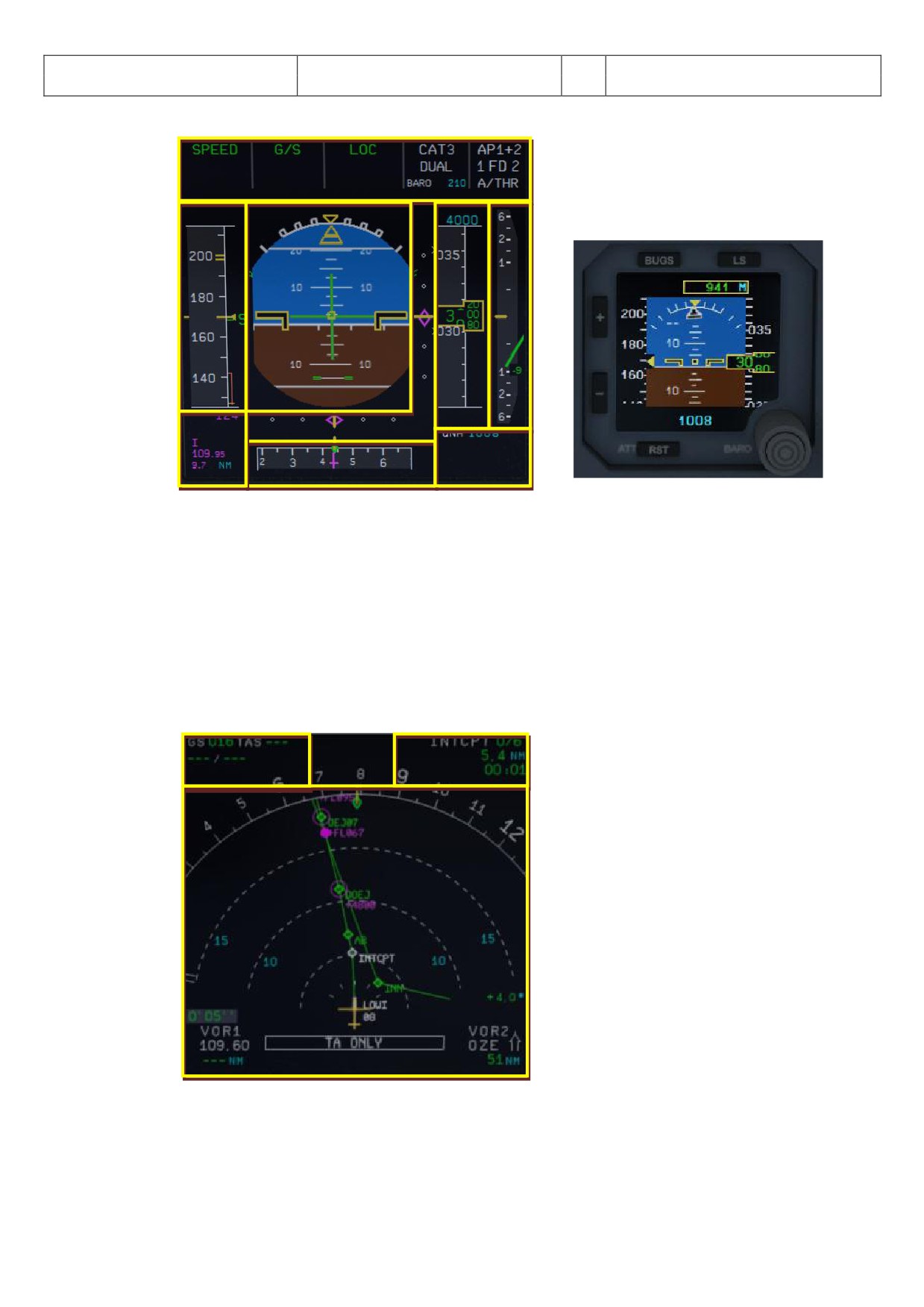
Picture 6: Glareshield and Main Panel (F9)
1 = PFD (Primary Flight Display)
8 = Dimmer for PFD and ND
2 = ND (Navigation Display)
9 = Master Warning and Master Caution Lights
3 = EFIS (Electronic Flight Information System)
10 = A/Skid & Nose Wheel Steering
4 = FCU (Flight Control Unit)
11 = Brake Fan
5 = E/WD (Engine- and Warning Display)
12 = EGPWS - Terrain on ND switch
6 = Brakes
13 = ISIS - Standby Altimeter
7 = Chronometer
Aerosoft
The Airbus A318/319/320/321 in FSX
Vol
06-01-07 Page 11
Airbus A318/319/320/321
Step-By-Step Tutorial
6
07 April 2015
2.1.1.
PFD - Primary Flight Display
1
5
6
3
2
4
7
9
8
Integrated Standby Instruments System (ISIS)
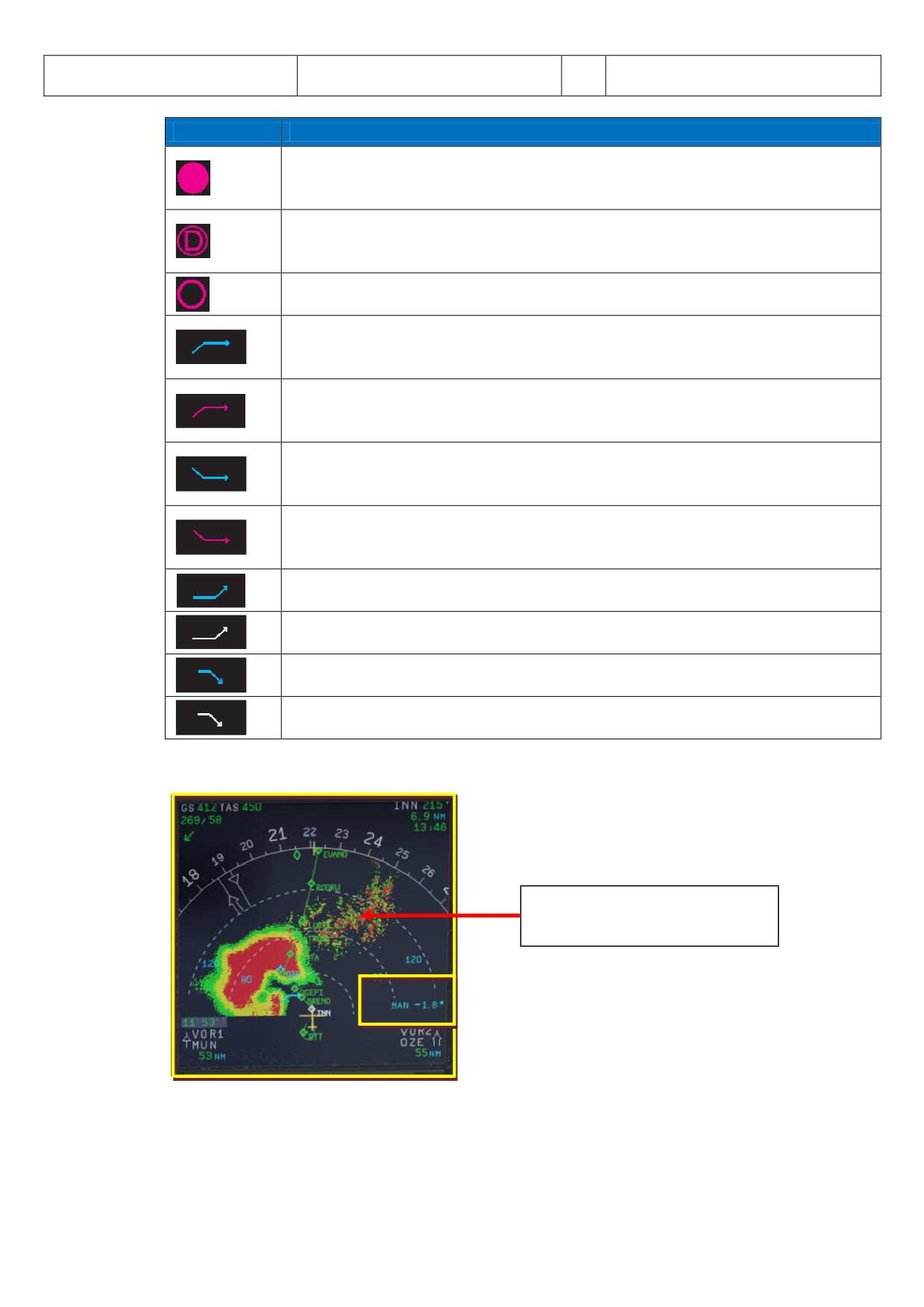
Picture 7: PFD - Primary Flight Display
1= FMA - Flight Mode Annunciator
2 = Speed Indicator
3 = Attitude Indicator - Artificial Horizon - Flight-Director Indicator
4 = Lateral and Vertical ILS Glide Path
5 = Altitude Indicator
6 = Vertical Speed Indicator
7 = ILS Identification
8 =Heading and Track Indicator
9 = Air Pressure
2.1.2. ND - Navigation Display (Standard)
1
2
3
4
Picture 8: ND - Navigation Display (Standard)
1= Speed (Ground Speed / True Air Speed) and wind (direction / speed)
2 = Next waypoint, degree, distance, time of arrival
3 = Lateral flight path
4= Chronometer time
Aerosoft
The Airbus A318/319/320/321 in FSX
Vol
06-01-07 Page 12
Airbus A318/319/320/321
Step-By-Step Tutorial
6
07 April 2015
Indication
Description
Speed Change: Indicates the point where the aircraft will initiate an automatic
acceleration or deceleration from current speed to new computed speed in case of
SPD LIM, SPD CSTR, or HOLDING SPD (including 250 knots below 10,000).
Deceleration Point: Indicates where the aircraft will initiate an automatic
deceleration toward VAPP. Managed NAV mode and managed speed must be
engaged.
Altitude Constraints: Constraint is predicted to be met when the aircraft is in
managed lateral and vertical modes.
Position where the aircraft will level-off at the FCU selected altitude. The same
symbol will indicate a level-off from a managed climb (CLB) or selected climb (OP
CLB).
Position where the aircraft will level-off at the constrained altitude entered in the
MCDU. The managed CLB mode must be engaged for the altitude constraint symbol
to appear and be honored.
Position where the aircraft will level-off at the FCU selected altitude. The same
symbol will indicate a level-off from a managed decent (DES) or selected descent
(OP DES).
Position where the aircraft will level-off at the constrained altitude entered in the
MCDU. The managed DES mode must be engaged for the altitude constraint symbol
to appear and be honored.
Start of climb with the CLB mode armed.
Start of climb with the CLB mode not armed.
Top of Descent or continue descent with DES armed.
Top of Descent or continue descent with DES not armed.
Picture 9: ND - Symbols
2.1.3.
ND - Navigation Display (WXR - Weather Radar)
Ground Clutter (only available in
MAN mode)
1
Picture 10: ND - Navigation Display (WXR)
1= TILT setting (green = MULTISCAN AUTO mode / blue = MAN mode)
The Airbus WXR works with FSX weather as well as with any weather add-on and displays what is
“injected” into the FSX weather.
Aerosoft
The Airbus A318/319/320/321 in FSX
Vol
06-01-07 Page 13
Airbus A318/319/320/321
Step-By-Step Tutorial
6
07 April 2015
Weather Radar Display
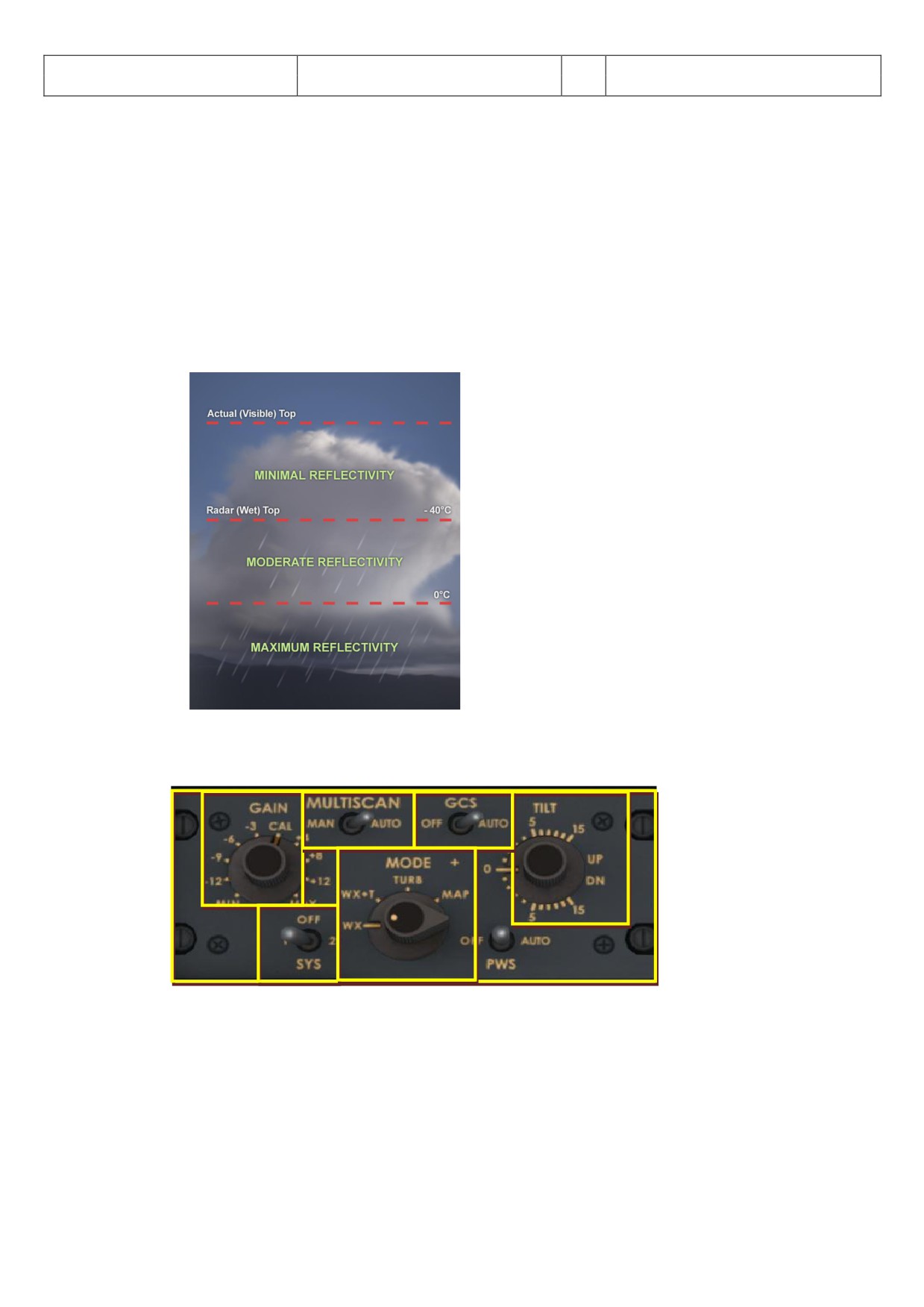
The weather radar display is depicted on the ND in any mode except PLAN. The selected ND range
scale will control the weather radar range.
The radar returns will appear in green, yellow and red depending on the precipitation intensity.
Black means “no” perception or perception with very low intensity (below level). The antenna tilt
angle will be displayed in the lower right-hand corner of the ND and is the angle between the
horizon and the radar beam axis. When MULTISCAN manual calibration mode is selected, MAN and
the setting appear in blue whereas in AUTO mode the setting appears in green.
If the TERR ON ND is selected on, the ND displays the surrounding terrain from the stored database,
and the weather radar display will be suppressed.
Picture 11: WXR - Reflectivity
WXR-Panel
2
3
4
5
6
1
Picture 12: WXR-Panel (Pedestal 2.5. # 11)
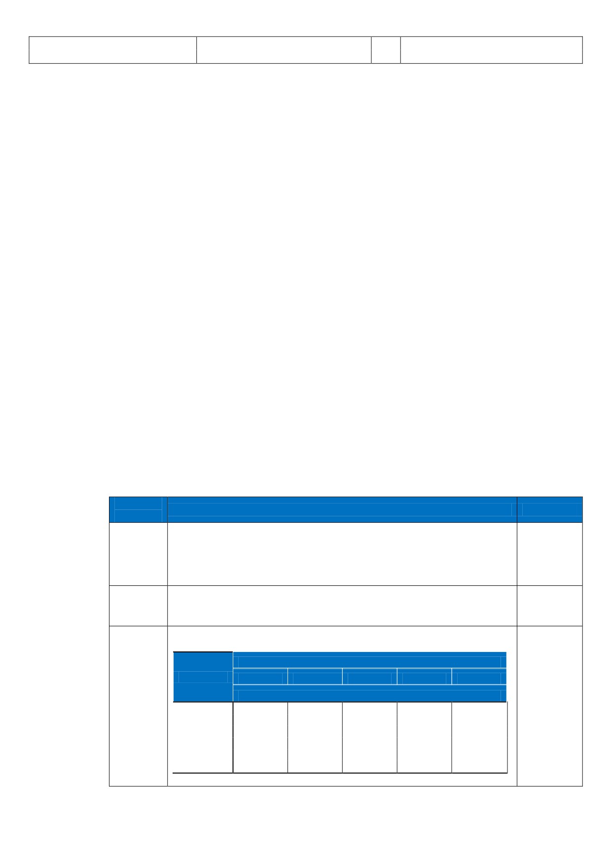
1= System = ON =1 or OFF - 2 is not modeled
2 = Gain control
3 = MULTISCAN (Manual and Auto)
4 = Ground clutter suspension (Off and Auto) - only in MAN mode
5 = TILT (UP and DOWN)
6 = MODE
The following features are modeled respectively can be operated in the Aerosoft A318/319/320/321
Airbus:
Aerosoft
The Airbus A318/319/320/321 in FSX
Vol
06-01-07 Page 14
Airbus A318/319/320/321
Step-By-Step Tutorial
6
07 April 2015
GAIN control
MULTISCAN (MAN and AUTO)
GCS (OFF and AUTO)
Antenna TILT
Mode
Range control of the ND (please see EFIS 2.1.5 #6)
Whereas the range control is handled on the EFIS for the other settings the WXR panel is used. To get
the maximum range / display it is necessary to have set FSX SETTINGS / WEATHER / CLOUD DRAW
DISTANCE to the maximum (if a weather tool is used apply the same settings to it).
AUTO MULTISCAN MODE
In auto mode (MULTISCAN switch set to AUTO) the tilt is automatically controlled. Two beams (upper
and lower) are merged together to become one picture representing weather in the possible vertical
flight path of aircraft.
Also in MULTISCAN AUTO mode the GCS (ground clutter suspension) is usually in AUTO mode and so
the ground clutter will be suppressed. Ground clutter can be suppressed by GCS in MULTISCAN mode
(AUTO), but not in manual mode (MAN) - using a lower tilt it will always be visible (except water
surface, which will be displayed in black).
MAN MULTISCAN MODE
In manual mode (MULTISCAN switch to MAN) the radar beam is controlled via the TILT rotary knob.
The flight crew uses the following three features to operate the Collins WXR2100 Weather Radar in the
Airbus A318/319/320/321 family (if MULTISCAN MAN is selected):
Gain control, which adjusts the sensitivity of the receiver (and should usually be set to AUTO).
Antenna tilt, that is the angle between the centre of the beam and the horizon
Range control of the ND, which has an essential influence on the optimum tilt setting
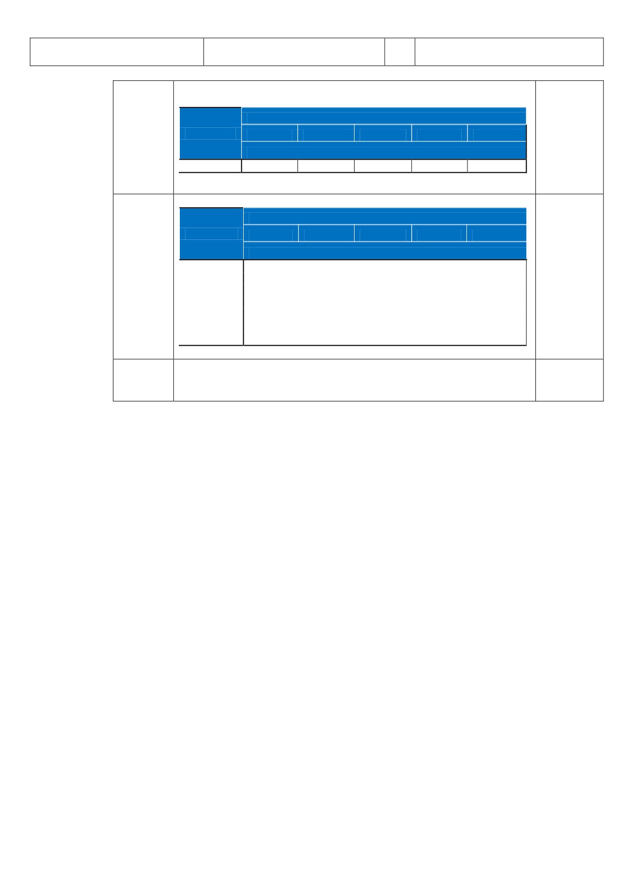
The recommended TILT settings for the various FLIGHT PHASES based on ALTITUDE and ND-RANGE
according to AIRBUS documentation (Flight Operations Briefing Notes) are:
Flight
Recommendations
Remarks
Phase
Taxi
Set ND to 10 NM range -
Radar check
Tilt down, then up: Check appearance / disappearance of ground returns
must be
performed
away from
people
Takeoff
Scan up to 15° UP for weather return, if significant weather is suspected- Select
Scan along
the departure
tilt at +4° UP for takeoff
path
Climb
Select negative tilt, maintain ground returns on top of ND as the aircraft climbs
Change TILT
(suggestions):
according to
altitude and
ND-Range
ND range
Flight Level
10
20
40
80
160
TILT SETTING
5.000
-0.9°DN
-0.1°DN
10.000
-2.7°DN
-0.8°DN
-0.5°DN
-0.4°DN
15.000
-4.5°DN
-1.4°DN
-1.0°DN
-0.9°DN
20.000
-6.3°DN
-2.8°DN
-1.6°DN
-1.5°DN
25.000
-8.8°DN
-4.3°DN
-2.4°DN
-2.1°DN
30.000
-10.8°DN
-5.4°DN
-2.8°DN
-2.4°DN
Aerosoft
The Airbus A318/319/320/321 in FSX
Vol
06-01-07 Page 15
Airbus A318/319/320/321
Step-By-Step Tutorial
6
07 April 2015
Cruise
Select negative tilt and maintain ground returns on top of ND. As a rule of thumb
No ground
use the following suggestions:
returns
beyond line of
ND-Range
sight:
Flight Level
20
40
80
160
320
FL370 => 240
TILT-Setting
NM
31.000
-12.1°DN
-5.8°DN
-3.1°DN
-2.5°DN
-2.5°DN
FL250 => 200
NM
Descent
Adjust tilt to maintain ground returns on top of ND. As a rule of thumb:
ND-Range
Flight Level
10
20
40
80
160
TILT SETTING
30.000
~ +3.0 °UP
25.000
~ +2.5 °UP
20.000
~ +2.0 °UP
15.000
~ +3.0 °UP
10.000
~ +2.0 °UP
5.000
~ +1.0 °UP
3.000
~ +0.5 °UP
Approach
Select tilt: +4° UP
To avoid
ground
returns
If you want to get more information on the WXR subject please have a look into the “Collins_WXR-
2100_Operators_Guide.pdf” as well as into AIRBUS documentation “Flight Operations Briefing Notes -
Adverse Weather Operations - Optimum Use of Weather Radar” which you can download from the
Internet.
MODE
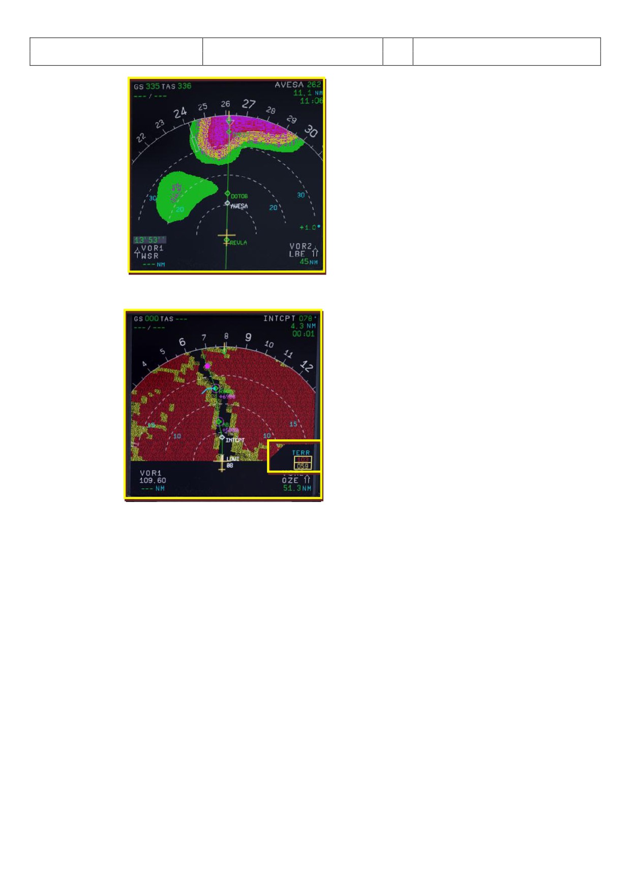
Turbulence is displayed in magenta out to maximal 40 nautical miles for all selected ranges (as in real
Airbus). No detecting of clear-air turbulence as only areas of precipitation are evaluated.
WX:
Normal WX Radar as it was implemented so far (precipitation targets).
WX+T: Precipitation targets with turbulence information overlaid.
TURB: Only turbulence information without precipitation targets.
MAP: Enables display of all radar echoes including terrain and precipitation information, but the
receiver sensitivity for precipitation returns is decreased so that terrain characteristics are
pointed out. No turbulence information is displayed.
Aerosoft
The Airbus A318/319/320/321 in FSX
Vol
06-01-07 Page 16
Airbus A318/319/320/321
Step-By-Step Tutorial
6
07 April 2015
Picture 13: ND - Navigation Display (Turbulences -magenta - )
2.1.4. ND - Navigation Display (EGPWS - Terrain on ND)
1
Picture 14: ND - Navigation Display (Takeoff at LOWI 08)
1= Lowest and highest elevation
EGPWS (Enhanced Ground Proximity Warning System) terrain picture
The ND displays the EGPWS terrain picture, when TERR ON ND switch is selected ON and the ND is not
in PLAN mode. The terrain picture replaces the weather radar image.
The EGPWS is automatically switched in case of a threat but suppressed if the following conditions are
met:
Departure: During first 60 seconds after takeoff (after getting airborne). Therefore the FMA modes
for thrust levers (TOGA, FLX, MAN TOGA, MAN MCT) and the SimOnGround flag are taken into
account.
Approach: Gear down + (Flaps 3 or 4 (full))
Approach: ILS is tuned and successful received and glideslope and localizer have both a deviation of
less than 2 dots
GoAround: During first 60 seconds after GO AROUND. Therefore the FMA modes for thrust levers
(TOGA, FLX, MAN TOGA, MAN MCT), flap position and flight status (GA) and the gear handle
movement into up position are taken into account.
Lowest and highest elevation
Minimum and maximum elevations encountered with selected range, are respectively displayed in this
square using the colors described below.
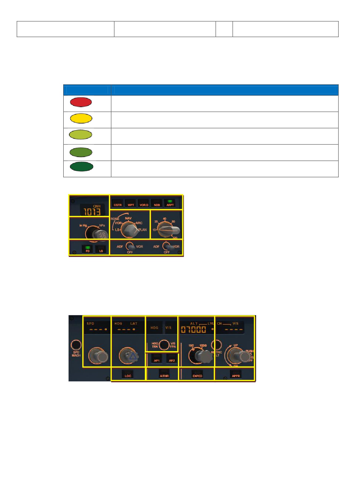
Aerosoft
The Airbus A318/319/320/321 in FSX
Vol
06-01-07 Page 17
Airbus A318/319/320/321
Step-By-Step Tutorial
6
07 April 2015
Terrain Display
The terrain appears in different colors and densities according to its relative height. The reference
altitude is projected downward from the actual aircraft altitude to provide a 30 second advanced
display of terrain when descending at more than 1000 FPM.
Indication
Description
High density red: Terrain is at least 2000 ft. above aircraft altitude.
High density yellow: Terrain is between 1000 ft. and 2000 ft. above aircraft
altitude
Low density green: Terrain is between -250 ft (gear down) or -500 ft (gear up) to
1000 ft above aircraft altitude.
Medium density green: Terrain is between 250 ft. (gear down) or 500 ft. (gear up)
to 1000 ft. below aircraft altitude.
High density green: Terrain is between 1000 ft. to 2000 ft. below aircraft altitude.
2.1.5.
EFIS - Electronic Flight Information System
4
1
5
6
2
3
7
Picture 15: EFIS - Electronic Flight Information System
1 = Air Pressure Display
5 = ND mode setting knob
2 = AP (Hg or hPa selector and setting knob)
6 = ND range setting knob
3= Flight Director / ILS
7 = ADF / VOR 1 and 2 switch
4 = Flight Plan Information on ND
2.1.6.
FCU - Flight Control Unit
10
1
2
3
4
5
6
7
8
9
Picture 16: FCU - Flight Control Unit
1 = Speed (display and setting knob)
6 = ILS lateral localizer
2 = Heading (display and setting knob)
7 = Auto throttle
3 = Altitude (display and setting knob)
8 = Expedite
4 = Climb / Descent (display/setting knob)
9 = Approach ILS lateral / vertical localizer
5 = Autopilot 1 and 2
10 = Heading Track / V/S Flight Path switch
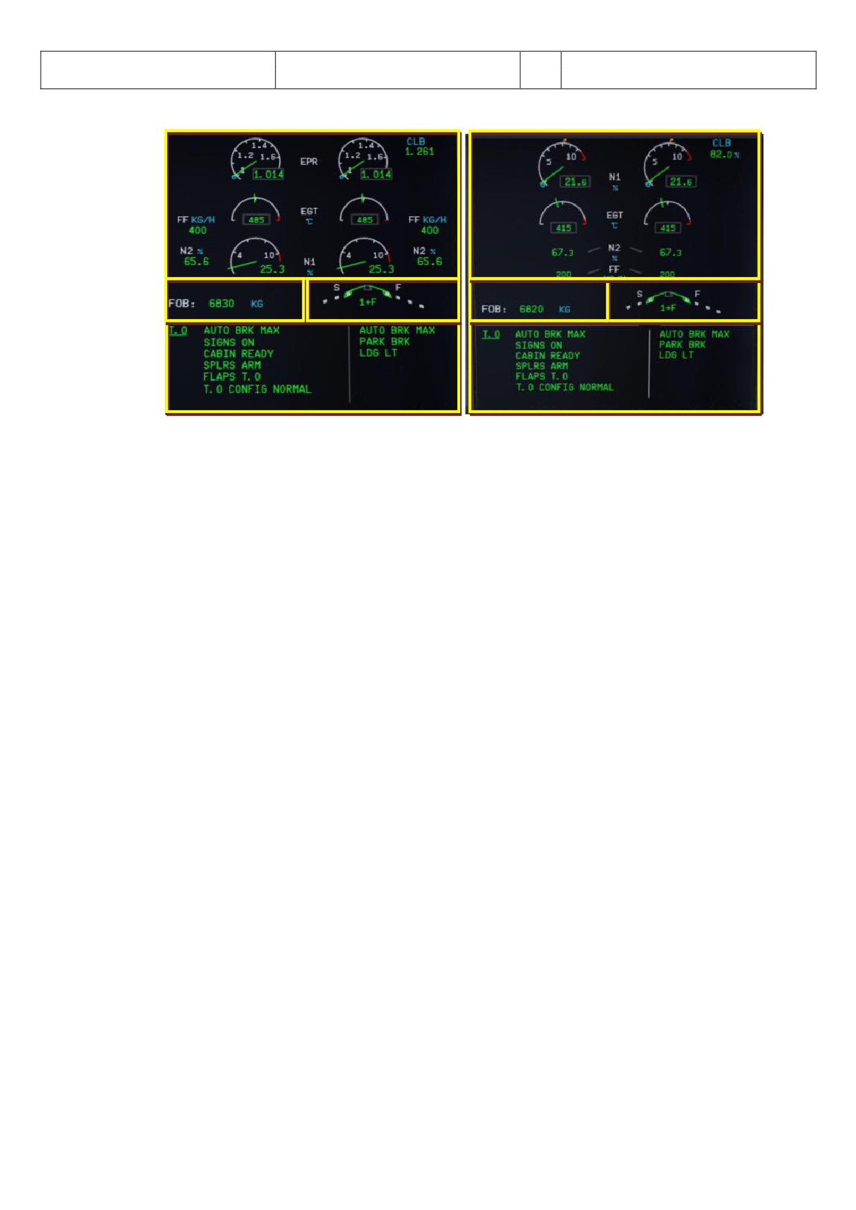
Aerosoft
The Airbus A318/319/320/321 in FSX
Vol
06-01-07 Page 18
Airbus A318/319/320/321
Step-By-Step Tutorial
6
07 April 2015
2.1.7. E/WD - Engine- and Warning Display
1
1
2
3
2
3
4
4
Picture 17: E/WD-Engine Warning Display with IAE resp. plane with CFM Engines
1= Engine Information
3= FLAPS Status
2 = FOB = Fuel on board
4 = Status Information, Takeoff- or Landing-Menu
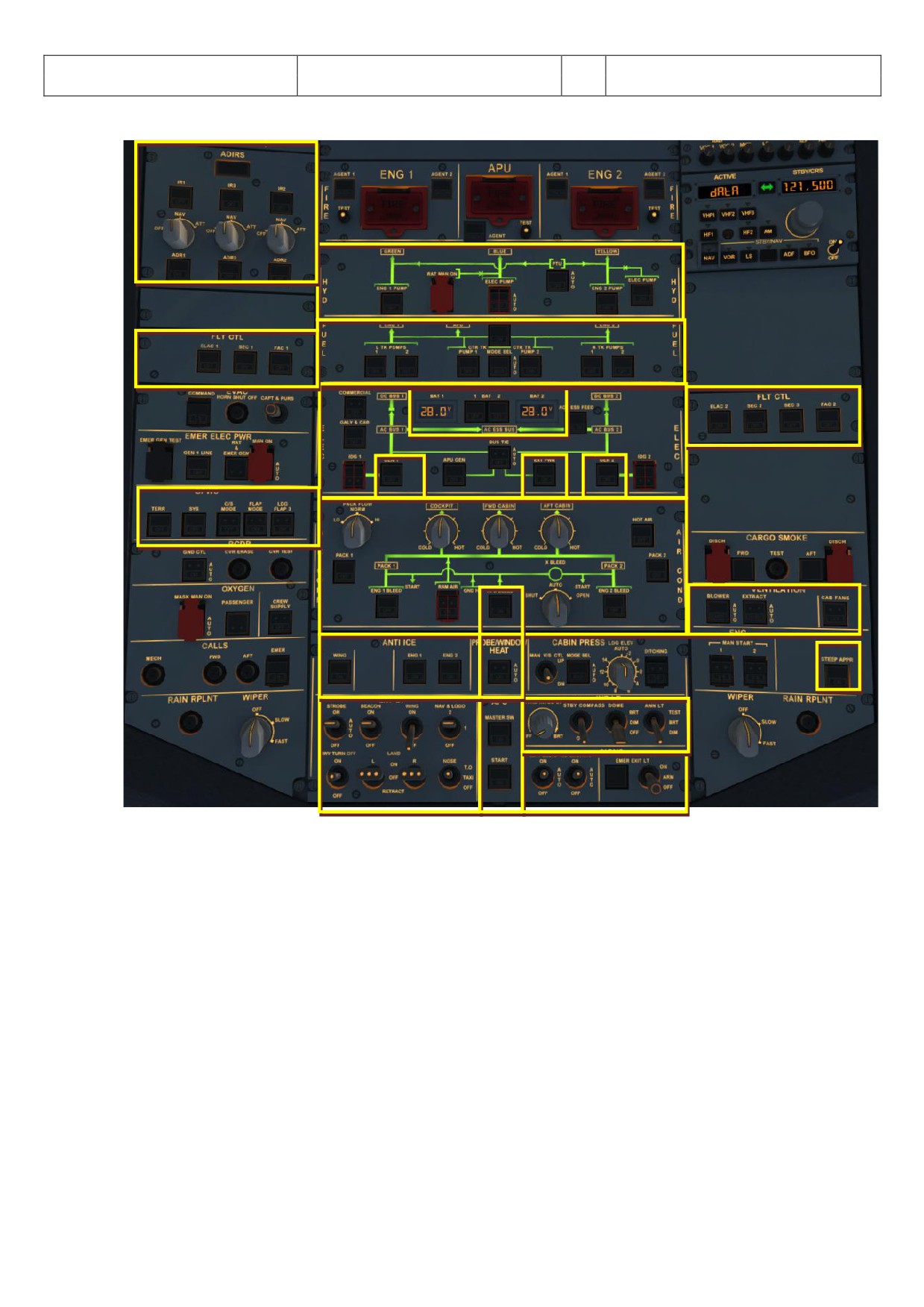
Aerosoft
The Airbus A318/319/320/321 in FSX
Vol
06-01-07 Page 19
Airbus A318/319/320/321
Step-By-Step Tutorial
6
07 April 2015
2.2
Overhead Panel
17
1
2
16
4
16
3
5
6
5
15
7
10
14
8
13
18
11
10
12
9
Picture 18: Overhead Panel (F12)
1 = Hydraulic Panel
10 = APU-Master / -Start & -Bleed
2 = Fuel Panel
11 = Internal Lights (Cockpit - Test)
3 = Electric Panel
12 = Signs (No Smoking, Seat B. and Emergency)
4 = Batteries 1 and 2, Voltage
13 = Probe Window Heat
5 = Generators 1 and 2
14 = Ventilation
6 = External Power
15 = GPWS (Ground Proximity Warning System)
7 = Air Condition Panel
16 = Emergency Flight Control System
8 = Anti-Ice-Panel
17 = ADIRS
9
= External Lights
18 = STEEP APPR. Button (A318 only)
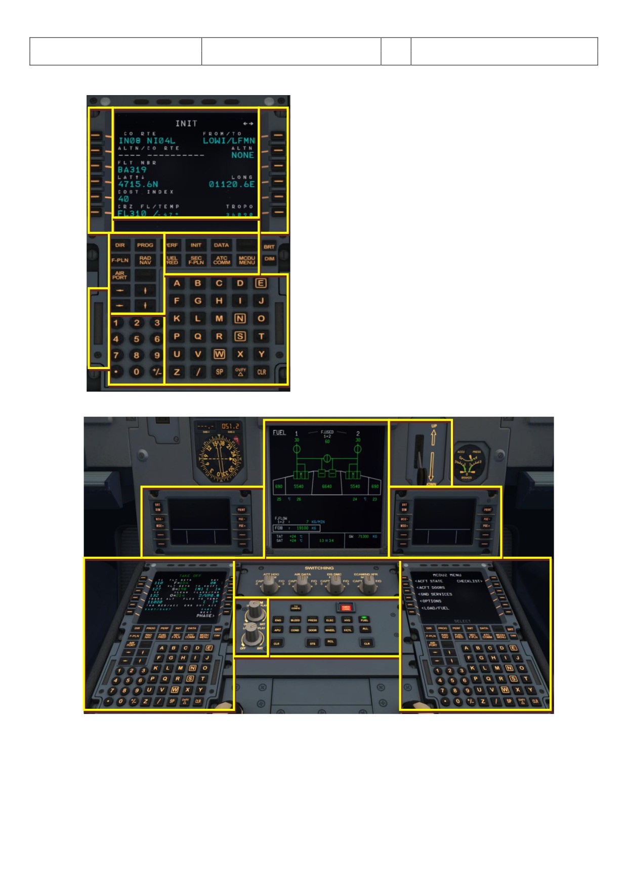
Aerosoft
The Airbus A318/319/320/321 in FSX
Vol
06-01-07 Page 20
Airbus A318/319/320/321
Step-By-Step Tutorial
6
07 April 2015
2.3
FMGC - MCDU - Multifunction Control and Display Unit
Picture 19: MCDU (SHIFT+2)
2
3
1 = Display
1
2 = LSK 1-6L = Line Select Key 1-6 left
3 = LSK 1-6R = Line Select Key 1-6 right
4 = Scratch pad
5 = Page keys
4
6 = Keyboard (numeric)
7 = Keyboard (alphabetic)
5
8 = Switch for input via PC keyboard
5
8
7
6
2.4
ECAM (Electronic Centralized Aircraft Monitoring)
2
6
1
6
3
3
4
5
Picture 20: ECAM (F10)
1 = ECAM (Electronic Centralized Aircraft Monitoring)
2 = Gear
3 = MCDU - Multifunction Control and Display Unit - left and right
4 = Dimmer for Upper and Lower ECAM Display
5 = ECAM Panel
6 = CPDLC = Controller Pilot Data Link Communication system
Aerosoft
The Airbus A318/319/320/321 in FSX
Vol
06-01-07 Page 21
Airbus A318/319/320/321
Step-By-Step Tutorial
6
07 April 2015
2.5
Pedestal
1
1
4
2
2
3
3
5
9
11
10
6
8
7
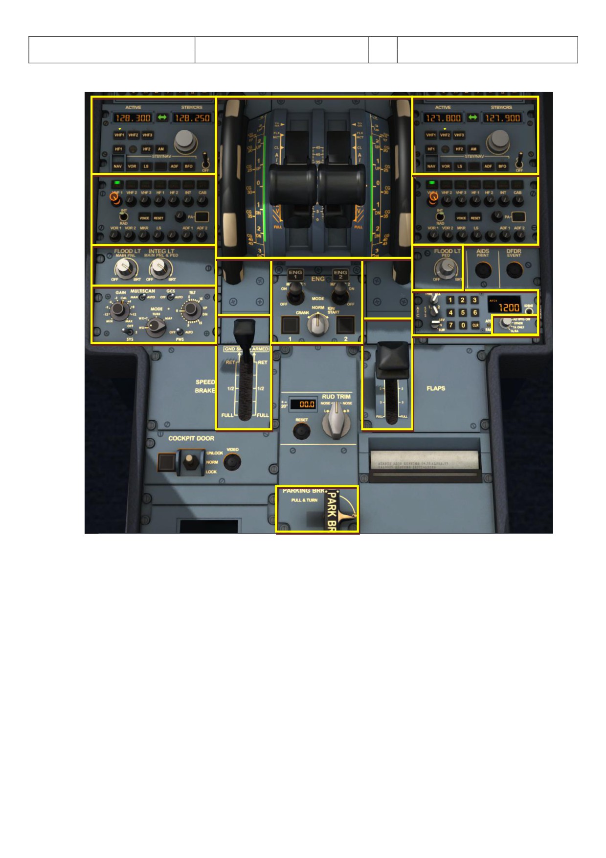
Picture 21: Pedestal (F11)
1 = Radio
2 = Audio
3 = Cockpit Panel Light
4 = Pitch Trim and Thrust Levers
5 = Engine Mode and Master
6 = Spoiler / Speed Brakes Lever
7 = Parking Brakes
8 = Flaps Lever
9 = Transponder
10 = TCAS - Traffic Alert and Collision Avoidance System
11 = WXR Panel
Aerosoft
The Airbus A318/319/320/321 in FSX
Vol
06-01-07 Page 22
Airbus A318/319/320/321
Step-By-Step Tutorial
6
07 April 2015
3.
General Information / Tips:
3.1
Additional Information:
Users who want to get full and accurate information on this very complex product, its systems and function
will find a lot of information in the various manuals which you will find in the main FSX-folder under
Aerosoft/Airbus A318_A319/Documentation or Aerosoft/Airbus A320_A321/Documentation.
3.2
Pictures:
The following description of the tutorial flight and its steps refers to the previously mentioned pictures and
terms so that it is easier to find the knobs, switches and buttons.
3.3
Procedure- and Checklist:
Based on the original Airbus A320 CFM procedure- and checklist, an in content and sequence modified
procedure- and check list has been prepared for the Aerosoft Airbus A318/319/320 and 321. These lists are
part of and used in this tutorial as well as in the checklist function (please see chapter 4.7 and chapter 5.1 for
details).
3.4
Using the Switches and Knobs, and changing values
To switch a button, knob or switch to ON, please use the left mouse button - whereas to switch it to OFF
please use the right mouse button. To change a “switch setting” or “values” just use the mouse wheel
Switch setting:
to the right = forward / to the left = backwards
Value:
increase = forward / decrease = backwards
3.5
Saving a certain flight and aircraft state
After installation of SP3 it is now possible to save a complete flight (situation and aircraft state - including all
MCDU2 settings) just with one click. Just use the FS-menu function to save the complete flight. It is not
necessary anymore to save the aircraft state separately and therefore this MCDU2 menu option has been
deleted.
When saving a certain “flight” with “state” and the checklist- / copilot function is set to ON, one checklist must
have been completely finished and the next one should be available. This means e.g. you can save a state
“ENGINE START” after the “BEFORE PUSHBACK AND START” checklist has been finished. So as a good “point”
for saving a flight we recommend are the above mentioned states or BEFORE TAKEOFF, DURING CLIMB, AT
CRUISE LEVEL, BEFORE T/D, BEFORE TRANS ALT or BEFORE 10.000 feet (which one ever comes first). But also
make sure that a certain FMA state is completely reached e. g. the FMA displays not ALT* anymore but just
ALT.
The saved flight can be loaded only from within FSX (not possible from the Free Flight Menu) whereas in
Prepar3D you can already use the Training Scenario Setup to load the saved flight.
After the flight has been completely loaded (takes some time based on your system) just move the thrust
levers into the right position. On the INFOBAR the following message p. e. during CLIMB will be displayed:
This means on the FMA: THR CLB, SPEED or THR IDLE should be displayed after adjusting the thrust levers..
Saved flights can be completely deleted using the FS-option. But this is only valid for those files which are
saved in User\Own Documents\Flight Simulator X Files or \Prepar3D v2 Files. The MCDU settings file which is
automatically saved in User\Own Documents\Aerosoft\Airbus has to be manually deleted.

Aerosoft
The Airbus A318/319/320/321 in FSX
Vol
06-01-07 Page 23
Airbus A318/319/320/321
Step-By-Step Tutorial
6
07 April 2015
3.6
Saving flight plans
The Aerosoft Airbus A318/319/320/321 defaults to the realistic company route format e. g. flight plans (except
departure runway, SID, arrival runway and STAR / TRANS) can be saved and loaded. After entering the
complete flight plan into the MCDU change to MCDU Menu and select a name for that flight plan like
LOWILFMN01. The save will be confirmed
(folder: C:\User\Your Name\Own Documents\Aerosoft\
Airbus\FlightPlans).
If you want to use this flight plan just enter the given name into the scratchpad on the INIT A page and then
press LSK1L (CO RTE = Company Route). The other way is (if you do not know the exact name) just enter the
departure / destination airport (like LOWI/LFMN with LSK1R) and on the next page all saved company routes
for this departure / destination airport are displayed. Using the respective LSK?L you can select the wanted
route.
But if you prefer to save your company routes with runways and SID/STAR as well as TRANS use the
Aerosoft. AirbusX.A318_19.Configurator (FSX Main Folder\Aerosoft\Airbus A318_A319)
AirbusX.A320_21.Configurator (FSX Main Folder\Aerosoft\Airbus A320_A321)
to make you preferred settings.
3.7
Sound (background)
Using the right MCDU pages “MCDU2 MENU” and “SOUND” there are three background sounds available
CABIN CREW, FLIGHT CREW and ATC. To use these sounds just click on the respective LSK and the description
changes to green = ON.
3.8
Tutorial Flight with Aerosoft A319 CFM:
Even that this tutorial flight is originally written for the A319 it can also be used for flights with other models
because the layout of all planes is identical. Only certain data like fuel and payload as well as performance and
speed data may vary.
The flight goes from Innsbruck/Austria (ID: LOWI) to Nice/France (ID: LFMN) and the following original flight
plan will be used:
LOWI - INN UM726 BZO UM984 EVANO UZ185 BORDI - LFMN
Picture 22: Flightpath Innsbruck (LOWI) to Nice (LFMN)
Aerosoft
The Airbus A318/319/320/321 in FSX
Vol
06-01-07 Page 24
Airbus A318/319/320/321
Step-By-Step Tutorial
6
07 April 2015
It is a “real” one also used by commercial airlines. The terminology of the above flight plan is as follows: We
are flying from Innsbruck (LOWI) to the first waypoint INN and then using the airway UM726 until the
waypoint BZO. From there we are using the airway UM984 to EVANO and then the airway UZ185 to BORDI.
From BORDI we are then flying to NICE (LFMN).
If you want to use such as the aforementioned “real” flight plan for further flights, those plans are available on
various websites - e.g. http://www.edi-gla.co.uk/fpl/search.php. To find aeronautical charts a very good
To reach our first waypoint (INN) from Innsbruck (LOWI) we have to use a SID = RTT2J (Standard Instrument
Departure). From all big airports there are such SIDs available depending on the takeoff-runway and first
waypoint of the flight plan. The same is valid for our arrival in Nice (LFMN). There are various STARs (Standard
Arrival Routes) as well as TRANS (Transitions) from the last STAR waypoint to the Final Approach Point - FAP in
case of an ILS, or to the Final Approach Fix - FAF, in case of a Non Precision Approach available. FAP/FAF is the
point where the instrument approach begins which is NI122 in this tutorial. The selection of the STAR / TRANS
or VIA depends on the last waypoint of the flight plan (BORDI) and the landing runway (STAR = BORD6C and
TRANS = NERAS).
How to enter this flightplan into the MCDU is explained in chapter 0. There are tools like FS Commander, EFB
or PFPX available which you can use to prepare a flightplan and those tools also offer an export function of
flightplans to the Aerosoft Airbus A 318/319. But currently only flightplans created with FS Commander and
EFB are exported including runways, SID, STAR and TRANS/VIA. Those tools fully support the Aerosoft Airbus
A318/319/320/321 flightplan functionality.
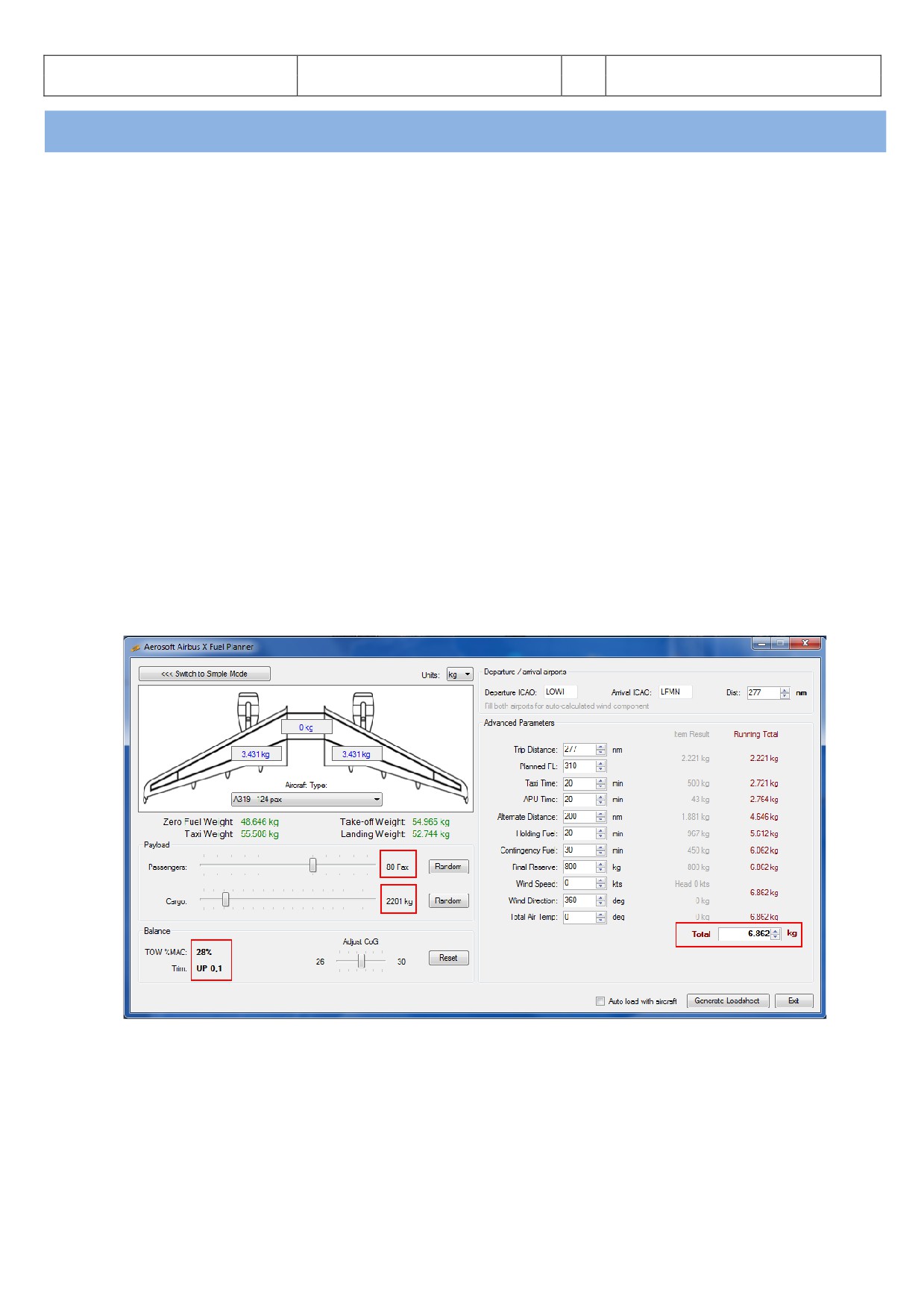
Aerosoft
The Airbus A318/319/320/321 in FSX
Vol
06-01-07 Page 25
Airbus A318/319/320/321
Step-By-Step Tutorial
6
07 April 2015
4.
Flight Preparation:
4.1
Fuel and Payload Planning:
A planner for passengers, cargo and fuel is included in this package. After installation you should find the
respective icon on your desktop (the installer will have added a shortcut on your desktop but you can also find
the program in your FSX Main Folder under Aerosoft\Airbus_Fallback\Aerosoft.AirbusX.FuelPlanner.exe.
Please start the Fuel- and Payload-Planner and it will open in “Simple Mode”. The following assumptions are
used in “Simple Mode”:
FL: 380
Taxi time: 20 min
APU time: 20 min
Alt dist: 200 nm
Holding time: 20 min
Contingency time: 30 min
and no wind or temperature factor. If any of these values differs a considerable amount from your planned
flight, then “Advanced Mode” should be used to alter the value. Because we will use for our tutorial flight a FL
of 31.000 please change to the “ dvanced Mode”.
Set the “UNIT” = Kg
Please select in “Aircraft Type” = A319
Set the passenger load to app. 80 Pax
Set the cargo load to app. 2.000 kg
Enter LOWI for “departure” and LFMN for “arrival”
Picture 23: Airbus A318/319/320/321 Fuel Planner (advanced planning mode)
Please check if all of the “Weight” values are shown in “green” e. g. are within the limits for the Airbus.
If
“ uto load with aircraft” is ticked and
“Generate Loadsheet” is pushed afterwards those settings
automatically will be loaded to the A318/319/320 or 321 if the plane itself is loaded in FSX. But if you want to
do the loading manually by yourself, then just untick “ utoload with aircraft” and only push “Generate
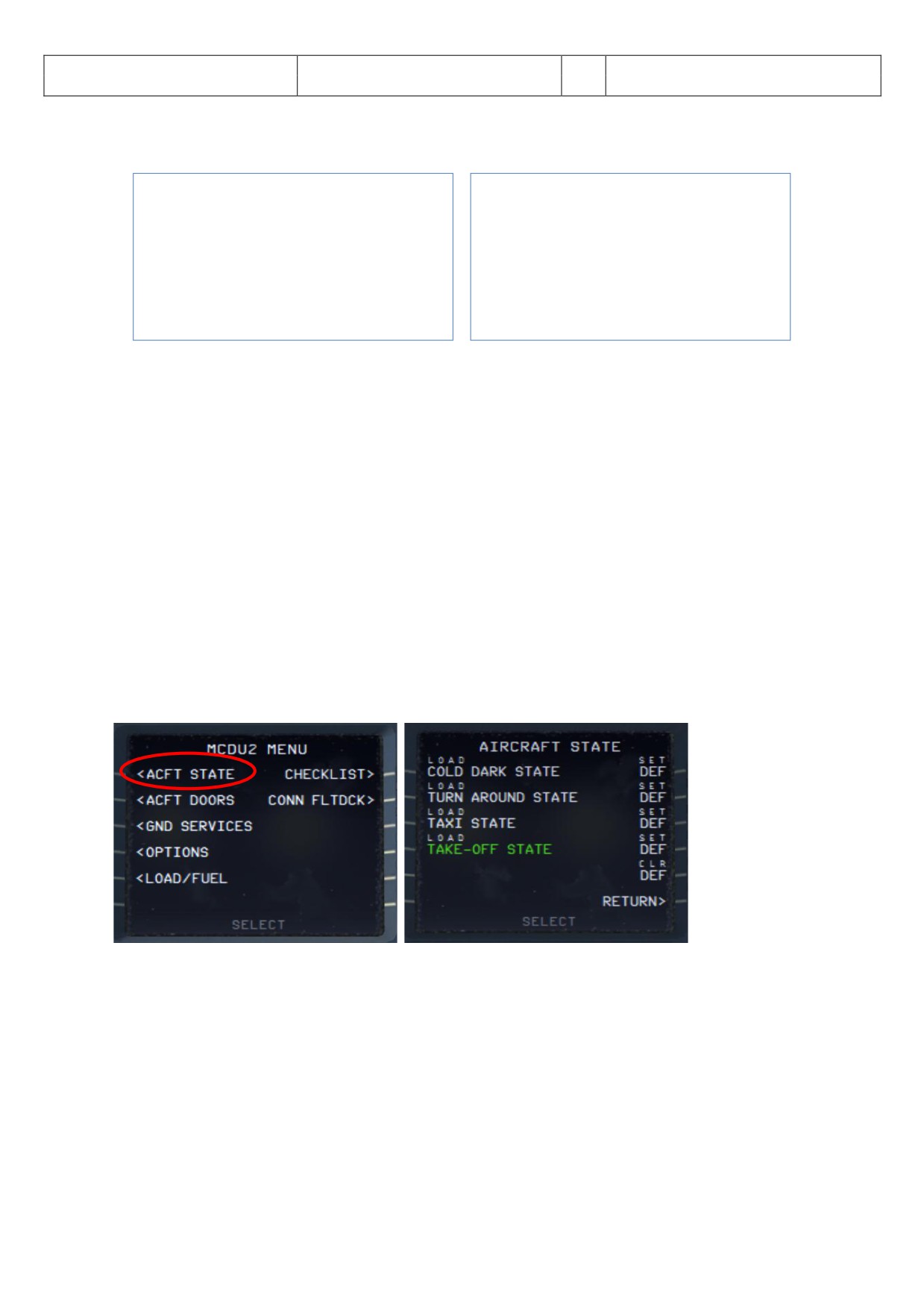
Aerosoft
The Airbus A318/319/320/321 in FSX
Vol
06-01-07 Page 26
Airbus A318/319/320/321
Step-By-Step Tutorial
6
07 April 2015
Loadsheet” (details for this functions please see chapter 4.7). Please also note that there might be small
differences between the values the “Fuel- and Payload-Planner” and FSX is stating after loading.
A319:
A320:
Empty weight
39.725 kg
Empty weight
41.243 kg
Payload
8.921 kg
Payload
8.921 kg
Zero Fuel Weight
48.646 kg
Zero Fuel Weight
50.164 kg
Fuel
6.862 kg
Fuel
7.615 kg
Gross Weight
55.508 kg
Gross Weight
57.779 kg
Picture 24: Total weight settings in Load-Manager
Please use the Aerosoft Airbus A318/319/320/321 Fuel- and Payload Planner only, not FSX to load the aircraft.
This is because the method of filling the tanks is different and the Aerosoft Planner is adjusted to Airbus
methodology.
4.2
Calculation of Takeoff Performance Data:
For programming the MCDU certain Takeoff Performance Data (ZFWCG, FLEX and THS, V1, VR and V2) are
required. In the original Airbus MCDU those data have to be manually entered by the crew during flight
preparation (based on various loading- and calculation sheets). In the Aerosoft Airbus A318/319/320/321 this
data is automatically calculated by the MCDU and displayed in the respective fields. Please note that V1, VR
and V2 can only be calculated after the takeoff flaps setting is entered into the MCDU.
If you want to use a more “sophisticated” way you have to calculate and manually enter those values yourself.
There are various tools available to calculate the takeoff performance data. One is the easy to use freeware
tool called TPC written by Roland Wukovits.
4.3
MCDU 2 MENU - ACFT STATE - Aircraft State Menu
Picture 25: Aircraft State Menu
To use the CHECKLIST and the COPILOT function it is necessary to load one of the menu - states. You access this
menu via the MCDU 2 Main Menu by selecting ACFT STATE. Please load COLD DARK STATE and the aircraft is
configured as you would find it on the first flight of the day, all systems are off.
fter setting the aircraft to “COLD DARK STATE” also the screen for the MCDU 2 is dark (because of no power).
To power the plane up (as well as the MCDU 2 screen):
Overhead Panel [F12] switch both batteries to ON section 4 (chapter 0)
Overhead Panel [F12] switch External Power to ON section 6 (chapter 0)