Airbus A318/319/320/321. FLIGHT CREW TECHNIQUES MANUAL (2005-2022) - page 14
Aerosoft
The Airbus A318/319/320/321 in FSX
Vol
06-01-07 Page 27
Airbus A318/319/320/321
Step-By-Step Tutorial
6
07 April 2015
To power up the various screens (PFD, ND, upper and lower ECAM) please switch on the respective panel lights
(Glareshield #8 and ECAM #4) as well as if necessary the “night” illumination using Pedestal #3.
It is possible every time an Aerosoft Airbus A318/319/320/321 is loaded that it is loaded already in a certain
state e.g. if you want the plane always to be loaded as COLD DARK, please use the option DEF (LSK 1R). If the
option is selected DEF will be marked in “green” (please see the picture above). To deselect the option just
press LSK 5 R.
If you are loading the TAXI or TAKEOFF states please are aware that the engines are already running with a little
bit of thrust i.e. app. 19-22 N1. This might be enough to make the plane already moving slowly. To program the
MCDU when TAXI or TAKEOFF is selected, therefore in those states the parking brakes are set. Also using these
aircraft states please first program the MCDU and set the Checklist- and Copilot function afterwards to ON.
After Installation of SP3 it is not possible anymore to save / load a defined “USER ST TE” (please see chapter
3.5).
4.4
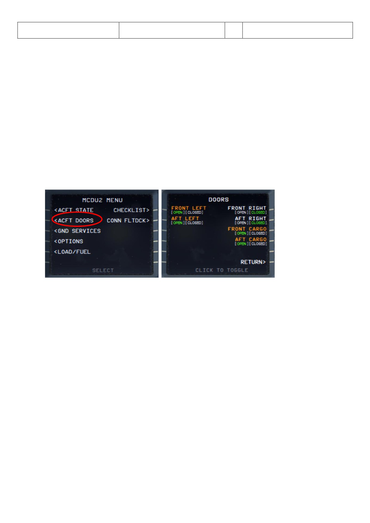
ACFT DORS - Aircraft Doors Menu
Picture 26: Aircraft Doors Menu
You access this menu via the MCDU 2 Main Menu by selecting ACFT DOORS. The DOORS option allows you to
open the doors and cargo hatches. If a door is open the specific door is marked in “red” and the situation
highlighted in “green”. To close / open a door just click on the specific LSK (line select key) in our case to close
the FRONT LEFT door just use LSK 1 L. Check if the FRONT LEFT door is at least opened (should be opened
automatically if you previously loaded the CFT ST TE “COLD DARK”). If you wish you can open the other doors.
Closing left side passenger doors as well as cargo doors are blocked when pax boarding and cargo loading
(MCDU2 LOAD/FUEL menu) is ongoing. Doors can be closed only if pax boarding and cargo loading (MCDU2
LOAD/FUEL menu - PAX/FREIGHT/FUEL = are green).
Aerosoft
The Airbus A318/319/320/321 in FSX
Vol
06-01-07 Page 28
Airbus A318/319/320/321
Step-By-Step Tutorial
6
07 April 2015
4.5
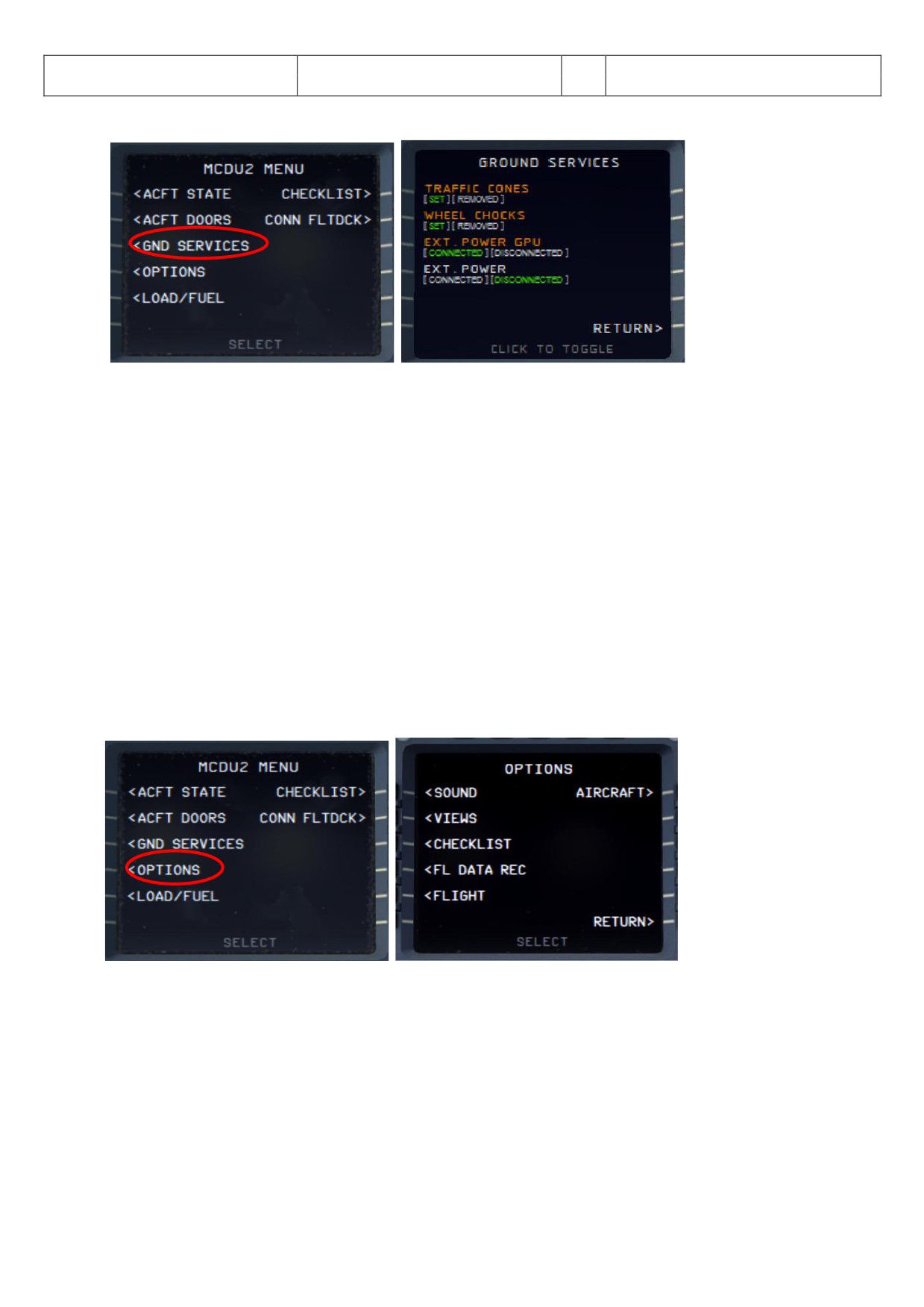
GROUND SERVICES - Ground Services Menu
Picture 27: Ground Services
You access the menu via the MCDU 2 Main Menu by selecting GROUNDSERVICES. The menu is available only if
the Wheel Chocks are SET or if the Parking Brake is ON (e. g. the aircraft now can park without Parking Brakes
set to ON).
The various options are only available if the following conditions are met:
CHOCKS:
Parking Brake is set to ON
CONES:
Only if CHOCKS are SET
EXT POWER: Parking Brake is ON or Chocks are SET
The Ground Services menu allows you to select various options. If an option is used the specific option is
marked in “orange” and the situation highlighted in “green”. To select an option just click on the specific LSK
(line select key) in our case to disconnect the EXT POWER GPU just use LSK 3 L. Check if the EXTERNAL POWER
GPU is at least available (should be available if you previously loaded the CFT ST TE “COLD DARK”). You may
select the other options as you wish.
4.6
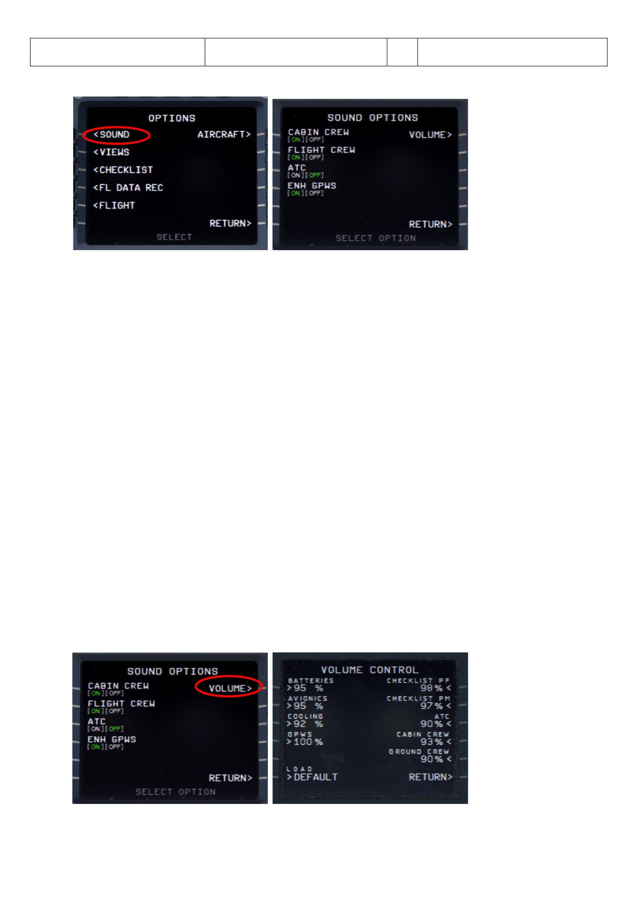
OPTIONS - Options Menu
Picture 28: Options Menu
Aerosoft
The Airbus A318/319/320/321 in FSX
Vol
06-01-07 Page 29
Airbus A318/319/320/321
Step-By-Step Tutorial
6
07 April 2015
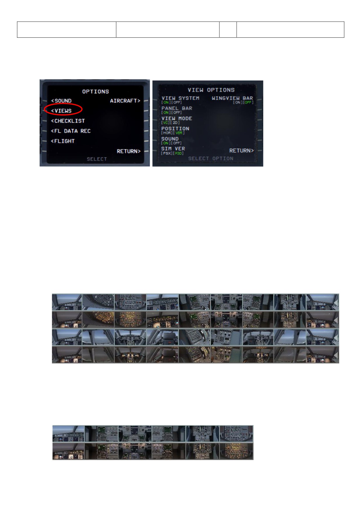
4.6.1 OPTIONS - SOUND
Picture 29: Sounds Configuration Menu
CABIN CREW
Background sounds by the purser like “Captain, all passengers are on board and the cabin is secured”
FLIGHT CREW
Background sounds by the flight crew like browsing in manuals, sneezing etc.
ATC
Background sounds from Air Traffic Controllers - instructions to other planes. There are 5 different channels
integrated (Ground, Tower, Departure, Center and Approach) playing according to the flight status.
Those options can be selected by clicking on the relevant left “LSK - Line Selection Key”. The relevant situation
(ON or OFF) is highlighted in “green”.
ENH GPWS - Enhanced Ground Proximity Warning System
If "ENH GPWS" is switched to ON the following sounds - callouts will be played:
"2500"
"1000"
"500"
"300"
“70”
“60”
"10"
“5”
"RET RD” - on autoland = at 10 ft R
(sequence “20” “RET RD” “5”) and on manual landing at 20 ft R
(sequence “RET RD” “10” “5”)
"100 Above" (100 feet above DH)
VOLUME
Picture 30: Volume Configuration Menu
Aerosoft
The Airbus A318/319/320/321 in FSX
Vol
06-01-07 Page 30
Airbus A318/319/320/321
Step-By-Step Tutorial
6
07 April 2015
Various sound volumes can be adjusted as required. Just enter the required value into the scratchpad and push
the appropriate LSK. To set all values back to the original values please use “DEF ULT”.
4.6.2 OPTIONS - VIEWS
Picture 31: View Configuration Menu
VIEW SYSTEM
The VIEW OPTION can be completely disabled so that there are no interferences for users who use TrackIR and
EZDOC.
PANEL BAR
There is also a Panelbar (can be customized using the right MCDU - MCDU MENU - OPTIONS - VIEWS)
integrated in this version of Airbus A318/319/320/321. Those options can be selected by clicking on the second
left “LSK - Line Selection Key”. If selected the ON respectively OFF is highlighted in “green”.
There are two different types of panel views available: The VC- and the 2D-mode and each with day and night
views (nights views are automatically used depending on FSX “current time” setting).
VIEW MODE = VC (Virtual Cockpit Views)
16 views with pictures (day and night versions)
Picture 32: VC Panel Bar (day and night version)
The VC-mode bar can be closed or opened again clicking on the “grey” triangle left and right on the bar. The
views 11 to 17 can be accessed using the mouse wheel. To access the ADIRS view just select the Overhead view
and then use the right mouse button.
VIEW MODE = 2D (Two Dimensional Cockpit Views)
11 views with pictures (day and night versions)
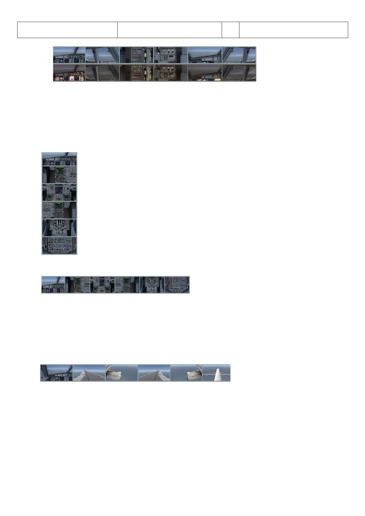
Aerosoft
The Airbus A318/319/320/321 in FSX
Vol
06-01-07 Page 31
Airbus A318/319/320/321
Step-By-Step Tutorial
6
07 April 2015
Picture 33: 2D Panel Bar (day and night version)
The 2D-mode bar can be closed or opened again by clicking on the “grey” triangle on the left of the bar. The
views 8 to 12 can be accessed using the mouse wheel. To access the upper overhead panel and ADIRS view just
select the overhead view and then use the right mouse button.
POSITION (VERTICAL or HORIZONTAL)
The bar can be either displayed horizontal or vertical on the left upper corner of the screen.
VERTICAL
Picture 34: Vertical Panel Bar
HORIZONTAL
Picture 35: Horizontal Panel Bar
WINGVIEW BAR
The bar can be either displayed horizontal or vertical on the right upper corner of the screen. There are in total
10 different views available (1 to 6 please see below). The views 7 to 10 can be accessed by going with the
mouse to the respective view then using the mouse wheel and clicking on it.
Picture 36: Wing View Bar
The bar can be closed or opened again by clicking on the “grey” triangle left and right on the bar.
SIM VER (FS-Simulator Version used)
Because in P3D the MENU BAR is not as transparent as in FSX in P3D the INFOBAR is displayed below the MENU
BAR. So if you use P3D please change the settings here.
Aerosoft
The Airbus A318/319/320/321 in FSX
Vol
06-01-07 Page 32
Airbus A318/319/320/321
Step-By-Step Tutorial
6
07 April 2015
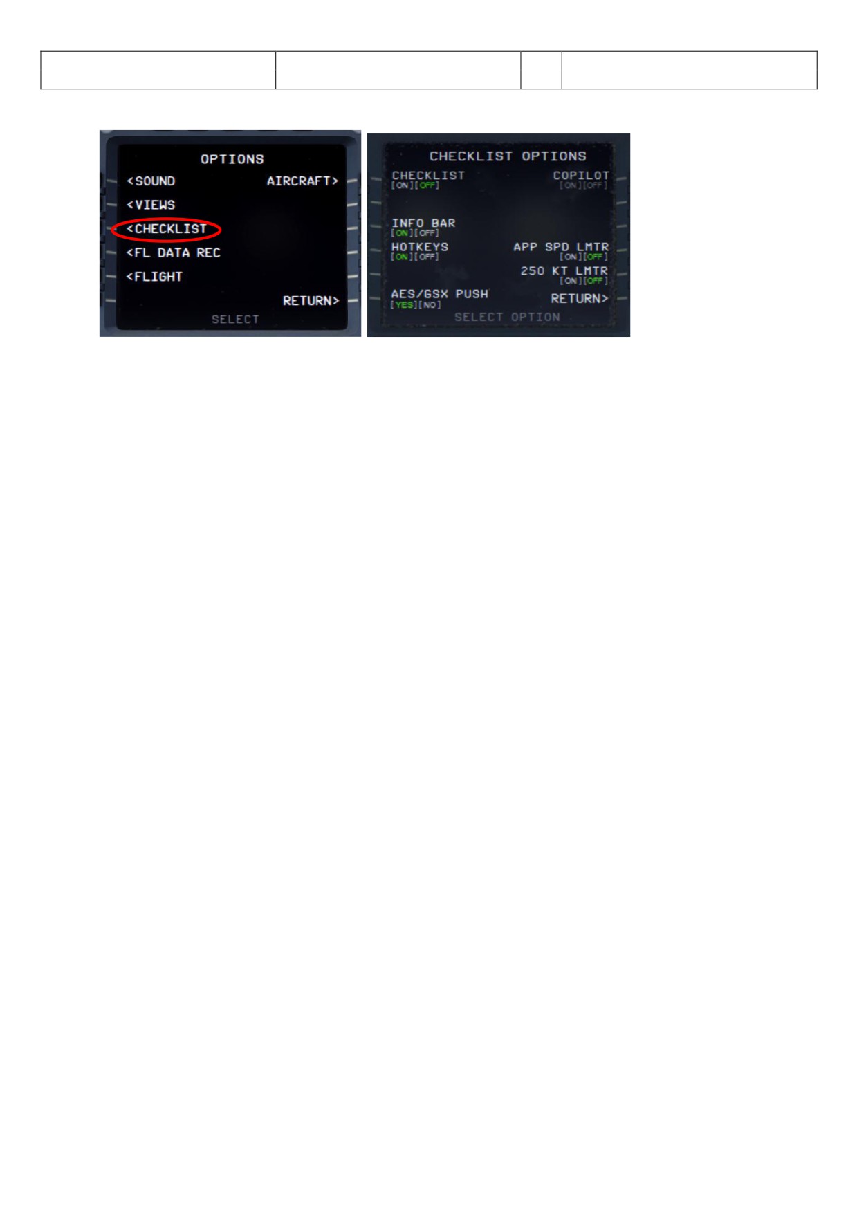
4.6.3 OPTIONS - CHECKLIST
Picture 37: Checklists Configuration Menu
CHECKLIST
Also an automatic checklist (with sound) is included in this Airbus A318/319/320/321 version. This option can
be selected by clicking on the first left “LSK - Line Selection Key”. If selected ON respectively OFF is highlighted
in “green”. The detailed checklist items you will find in chapter Fehler! Verweisquelle konnte nicht gefunden
werden.. etc. (marked in “green”).
But before setting the status to ON an original Aerosoft Airbus A318/319/320/321 panel or a user state should
be loaded, so that the system starts with right equivalent checklist state. In our case this should already have
been done e. g. the aircraft is already set to “COLD DARK”.
The checklists are connected to the used aircraft state e. g. if the “Taxi State” is chosen (MCDU MENU - ACFT
ST TE) then after setting picture 4 LSK1L to “ON” the systems starts with the “Taxiing Checklist”. This is also
valid for saved user states if those are saved after a checklist has been finished.
If a checklist item is constantly repeated it means that the Airbus item setting is not correct and cannot be
handled by the copilot (if this function is used). Then please correct the settings manually and the checklist
sequence will automatically be continued.
For our tutorial flight we will use the CHECKLIST function so please set it to ON (= green)
COPILOT
If the automatic checklist function is set to ON a copilot function (handling all actions performed by the PM -
PILOT MONITORING) becomes available. This option can be selected by clicking on the first right “LSK - Line
Selection Key”. If selected ON respectively OFF is highlighted in “green”. It also can be switched ON and OFF
using “2” from the keyboard - but not if the ACFT DOORS MENU page is active.
There are 2 different possibilities / combinations possible to use the “Checklist” and “Copilot” option or just the
“Checklist” option only.
If only “Checklist” is chosen then the duties of the copilot have to be handled manually by the user. In
this case the Copilot just reads the checklist items and waits until the correct settings are made - before
passing on to the next item. If settings are not made or are not correct the item is constantly repeated.
Certain items can also be skipped by using the SKIP ITEM function (see chapter 4.8).
If the combination is chosen then the “Copilot” works timely aligned with the checklist i.e. performs his
duties when the task should be done according to the checklist. Only certain items have to be handled
manually by the user (in the checklist marked in “red”).
The detailed tasks performed by the Copilot you will find in chapter Fehler! Verweisquelle konnte nicht
gefunden werden.. etc. (marked in “yellow”).
Aerosoft
The Airbus A318/319/320/321 in FSX
Vol
06-01-07 Page 33
Airbus A318/319/320/321
Step-By-Step Tutorial
6
07 April 2015
For our tutorial flight we will use the COPILOT function so please set it to ON (= green).
In case you want to use the Checklist- and Copilot function with TAXI and TAKEOFF states then please first
program the MCDU and set the Checklist- and Copilot function afterwards to ON.
INFOBAR
If “CHECKLIST” is set to ON this option becomes available. nd if “INFOB R” is activated on top of the screen an
info bar is displayed. This bar displays (based on the complete procedure list according to chapter 5.) the next
manually to be set action.
Picture 38: Info bar
This information appears after you loaded the CFT ST TE “COLD DARK” and the checklist- as well as the
copilot function has been set to ON. “MCDU: START CHECKLIST OR USE KEY ‘1’ means you can start the
“Cockpit Preparation Checklist” by clicking on the specific checklist in the menu or just press [1} on your PC-
keyboard.
In such cases the content of the infobar also contains a hint which keypad key alternatively can be used to start
the relevant checklist.
Start "COCKPIT PREPARATION CL" using "1"
Start “ENGINE ST RT WITH PUSHB CK CL” using "1"
Start “ENGINE ST RT CL” using "2"
As we will use the CHECKLIST and COPILOT function for our tutorial flight you should set the INFOBAR to ON
(= green).
HOTKEY
For certain selections or commands of the checklist- and copilot function we use the “1” and “2” from the
keyboard. E.g. you can start the “Cockpit Preparation” checklist just using “1” instead of starting it from the
right MCDU. But for certain other programs this might be a problem because those keys are already used for
other function. If you are running such programs like EZDOC then please set the function to OFF. In this case if
you want to start a checklist you always have to start it from the checklist menu.
AES/GSX PUSH
AES or GSX are separate programs and are not included in the Aerosoft Airbus package e. g. they have to be
bought separately. If those programs are not installed then set the option to NO.
The Aerosoft Airbus A318/319/320/321 does not automatically detect an airport where AES can be used. If the
AES / GSX pushback function should be used it is necessary to set this function to YES. Then during pushback
the conversation between PF (pilot flying) and Ground is aligned, the AES / GSX pushback function will be used
as well as the checklist and copilot function to start the engines.
If only the AES / GSX clearance procedure but no pushback shall be used, leave this function to NO. Then after
the AES / GSX procedure has been finished the checklist “ENGINE ST RT [2” has to be used and started.
APP SPEED LIMITER - (only available if COPILOT is set to ON)
If selected the copilot checks the speed limit of 250 knots (below 10.000 feet) and if this limit is exceeded, the
copilot automatically (using the speed brakes) reduces the speed to 250 knots. This function works without any
calls and in “Managed” as well as in “Selected” speed mode.
Aerosoft
The Airbus A318/319/320/321 in FSX
Vol
06-01-07 Page 34
Airbus A318/319/320/321
Step-By-Step Tutorial
6
07 April 2015
250 Knots LIMITER
If selected the copilot checks the speed limit of 250 knots (below 10.000 feet) and if this limit is exceeded, the
copilot gives a warning. No action is taken automatically.
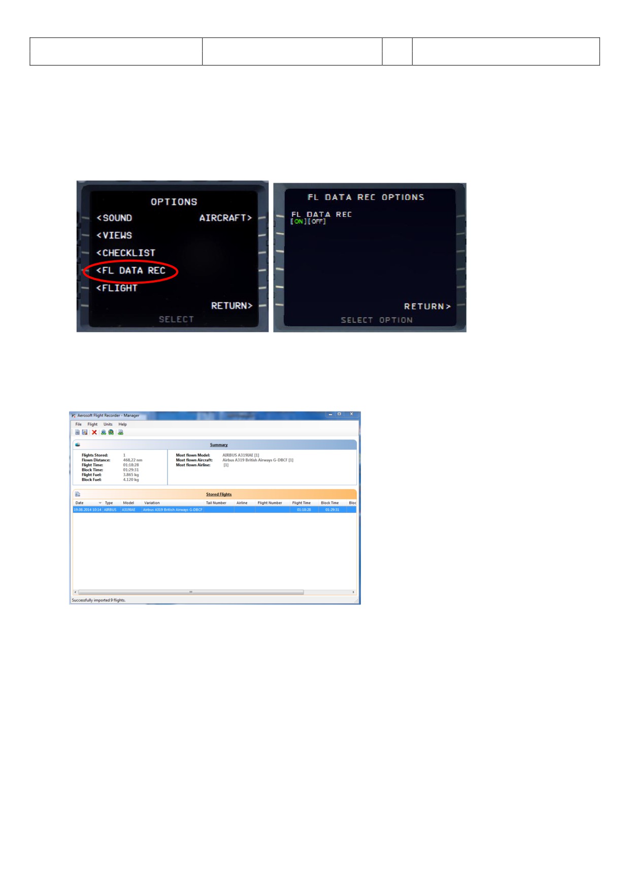
4.6.4 OPTIONS - FLIGHT DATA RECORDER
Picture 39: Flight Data Recorder
Using this menu it is possible to switch ON and OFF the Flight Data Recorder e. g. if set to ON the flight data will
be automatically “recorded”. To see this recorded data please open the AS-Flightrecorder. The system is saved
in the FSX Main Folder under Aerosoft \ Flight Recorder \ AS-FlightRecorderManager.exe. After starting the
recorder the following main screen opens showing all saved flight records.
Picture 40: Flight Data Recorder Menu
Aerosoft
The Airbus A318/319/320/321 in FSX
Vol
06-01-07 Page 35
Airbus A318/319/320/321
Step-By-Step Tutorial
6
07 April 2015
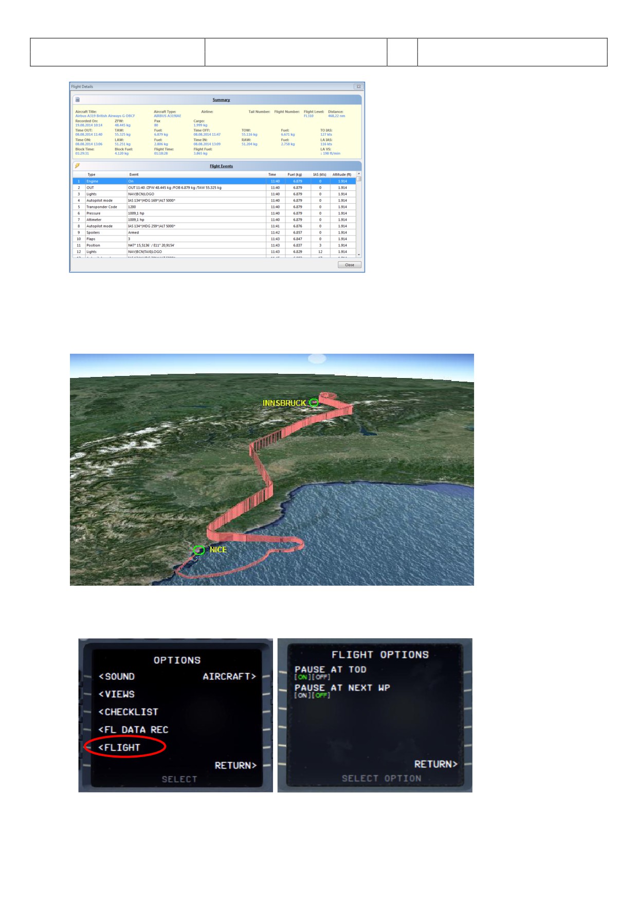
Picture 41: Flight Data Recorder - Details -
More details on the Flight Data Recorder (DFDR) you will find in the documentation Volume 4 “Systems” section
“Indicating / Recording systems” e.g. that the data can also be exported to GOOGLE EARTH (result please see
below )
Picture 42: Flight Data Recorder - Result in Google Earth -
4.6.5 OPTIONS - FLIGHT
Picture 43: Flight Options
Aerosoft
The Airbus A318/319/320/321 in FSX
Vol
06-01-07 Page 36
Airbus A318/319/320/321
Step-By-Step Tutorial
6
07 April 2015
PAUSE T ……
Using this menu it is possible to switch ON and OFF 2 different options to pause the FSX during a flight
PAUSE AT T/D (app. 20 miles before T/D so that the DESCENT PREPARATION checklist can be completed
before the descent really starts). FMA mode must be ALT CRZ or ALT CSTR
At next waypoint
Aerosoft
The Airbus A318/319/320/321 in FSX
Vol
06-01-07 Page 37
Airbus A318/319/320/321
Step-By-Step Tutorial
6
07 April 2015
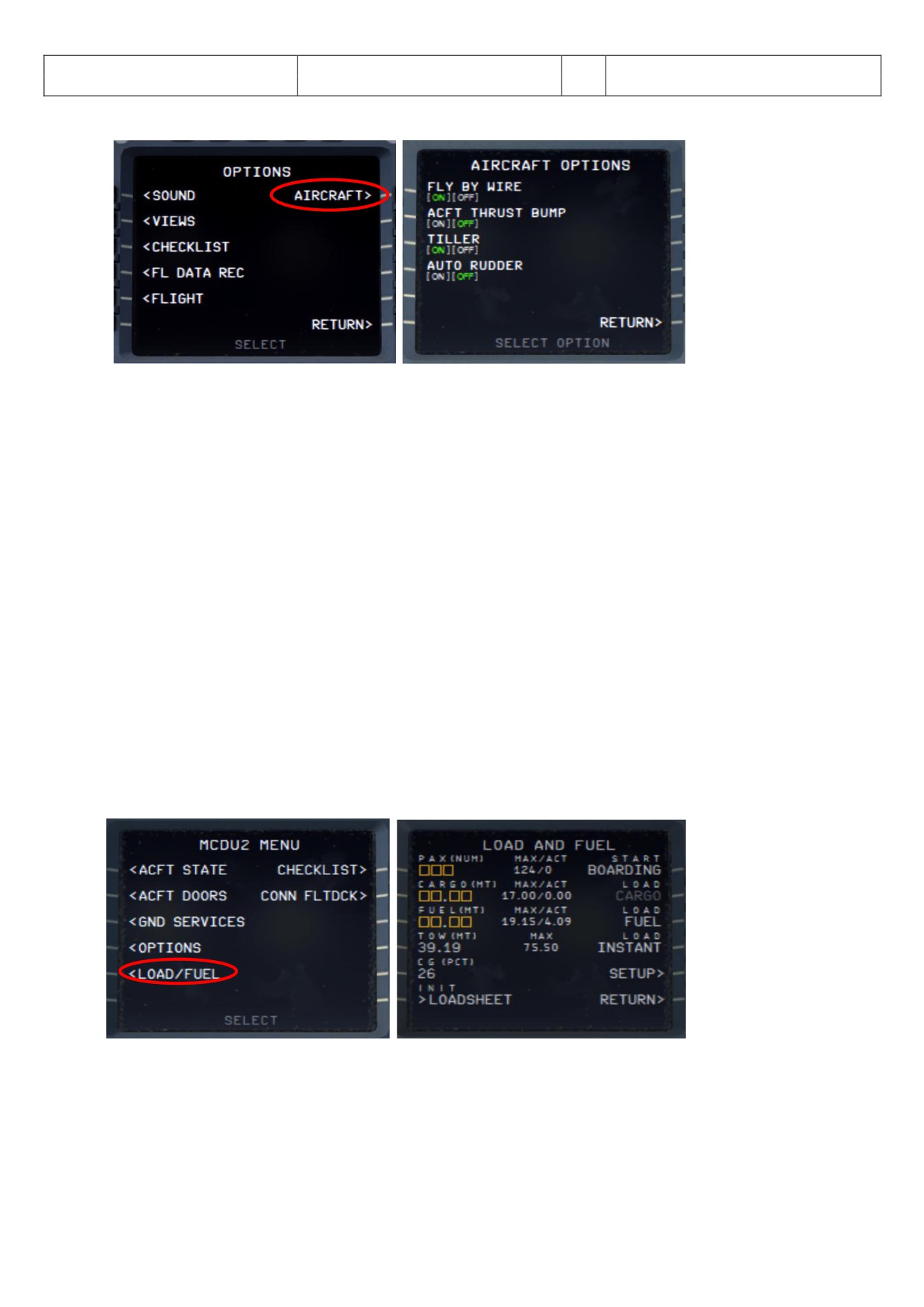
4.6.6 OPTIONS - AIRCRAFT
Picture 44: Aircraft Options
FLY BY WIRE ……
Using this menu option it is possible to switch ON and OFF the “FLY BY WIRE” function - OFF maybe necessary
for certain video recordings.
ACFT THRUST BUMP
This menu option (set to ON) enables an "unrealistic feature" where users can get additional thrust for takeoff
p. e. for “high” airports, at hot temperatures or short runways.
TILLER
The Tiller option allows you to de-activate the use of a standard Throttle 3 axis to control the tiller. On some
machines this axis is not available or already in use then set this option to OFF.
AUTO RUDDER
Setting Auto rudder in your FSX settings to ON you also need to set this in the right MCDU to ON. It disables the
Airbus A318/319/320/321 fly by wire function on the ground. This makes steering the Airbus A318/319/320/321
on the ground possible without using rudder pedals or a joystick with a rudder.
If this function here is set to ON then there will be no “rudder check” during the “ fter Engine Start” checklist.
4.7
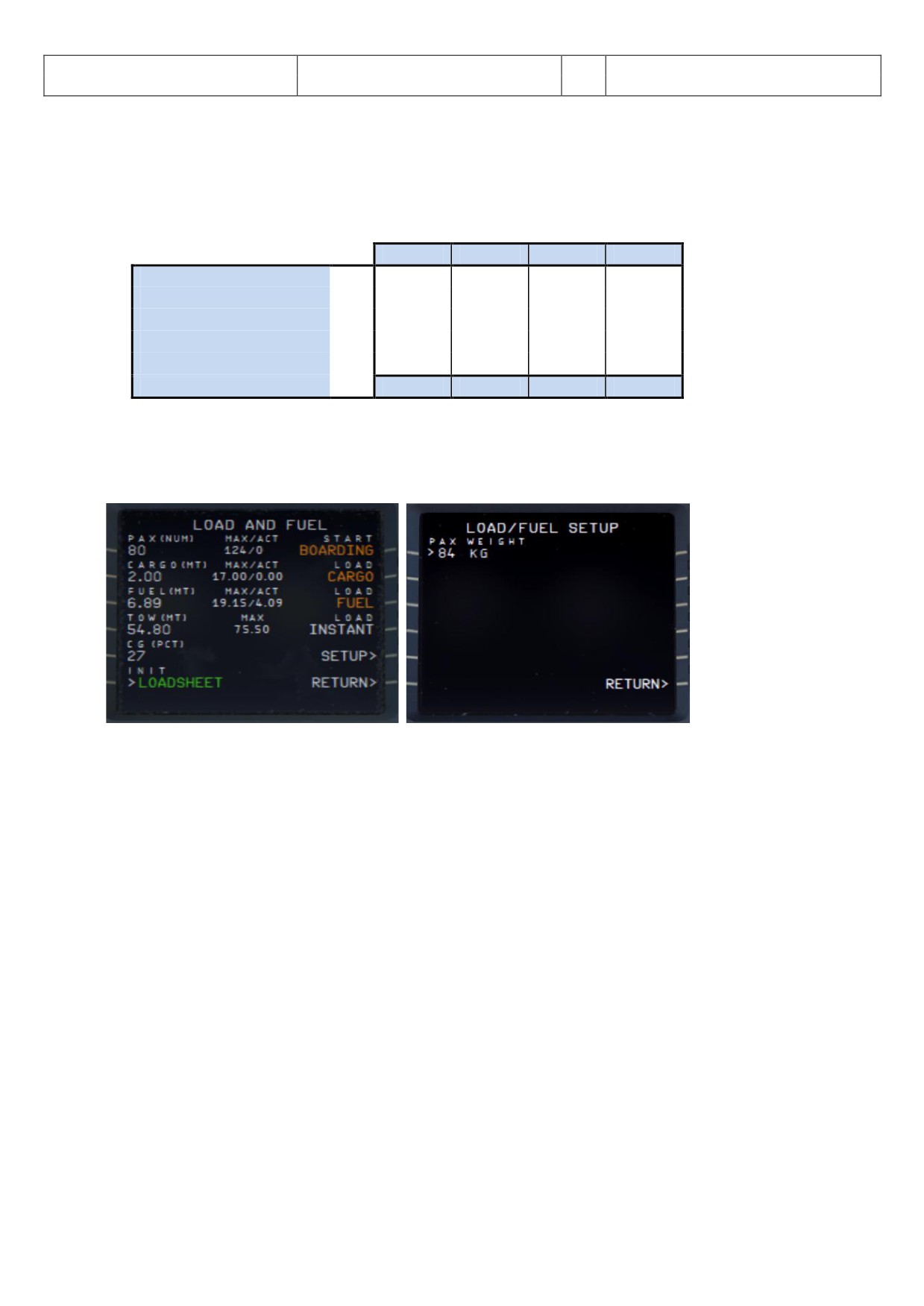
Load / Fuel
Picture 45: Load/Fuel Options
Conditions to use these functions (except LOAD INSTANT) are:
All Load Requests: Engines = off and parking brakes or chocks are set
Pax boarding: Front or aft door is open
Cargo: Both cargo doors are open
Aerosoft
The Airbus A318/319/320/321 in FSX
Vol
06-01-07 Page 38
Airbus A318/319/320/321
Step-By-Step Tutorial
6
07 April 2015
Init Loadsheet
Please push LSK6L and the data from the Fuelplanner Loadsheet (see chapter 4.1 for details) are automatically
loaded into the menu - but not into the plane (details you will find in the following paragraph “Load Process”).
But it is also possible to enter the data for PAX, CARGO and FUEL manually (within the limits according to the
model used -) please see table below:
A318
A319
A320
A321
Max. Passengers (Standard) No.
107
124
150
186
Max. Passengers (Special)
No.
132
156
180
220
Max. Cargo Weight
KG
17.00
17.00
17.00
17.00
Max. Fuel Weight
KG
19.15
19.15
19.15
19.15
Empty Weight
KG
39.50
40.80
41.24
46.85
Max. TOW
KG
68.00
75.50
77.40
89.00
If using the special seat configuration the pax weight should be adjusted accordingly. The defined weight per
passenger can be changed (SETUP = LSK5R) only in case of manual input. If the Fuelplanner Loadsheet data are
used the weight is fixed with 84 kg/pax.
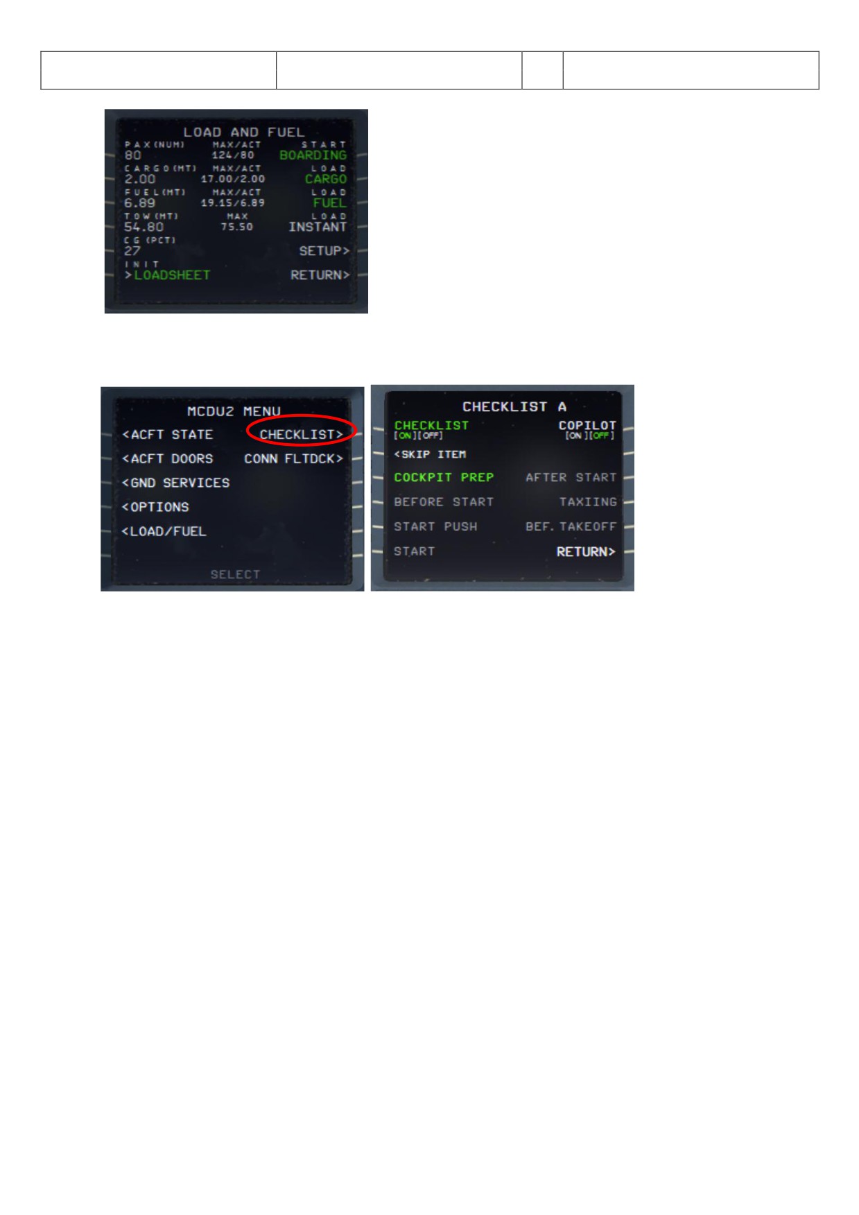
Picture 46: Load/Fuel Menu after INIT LOADSHEET
Load Process
If the loading process can be started the respective item is marked in “orange”. There are two ways to load pax,
cargo and fuel to the plane. INSTANT = Just push LSK4R and pax, cargo and fuel are immediately loaded whereas
using LSK1-3R the loading process takes some time like in the real world. The loading progress can be checked
by looking at the ACT values. During the loading process the respective items are flashing in “green” and if
loading is completed the flashing stops.
Using the TAXI or TAKEOFF aircraft state it is only possible to use LOAD INSTANT (if the parking brakes are set).
But for the 319 I E also using LO D INST NT it is not possible to “load” fuel (due to FF custom fuel flow
simulation) if engines are running.
Aerosoft
The Airbus A318/319/320/321 in FSX
Vol
06-01-07 Page 39
Airbus A318/319/320/321
Step-By-Step Tutorial
6
07 April 2015
Picture 47: Load/Fuel Menu after loading completed
4.8
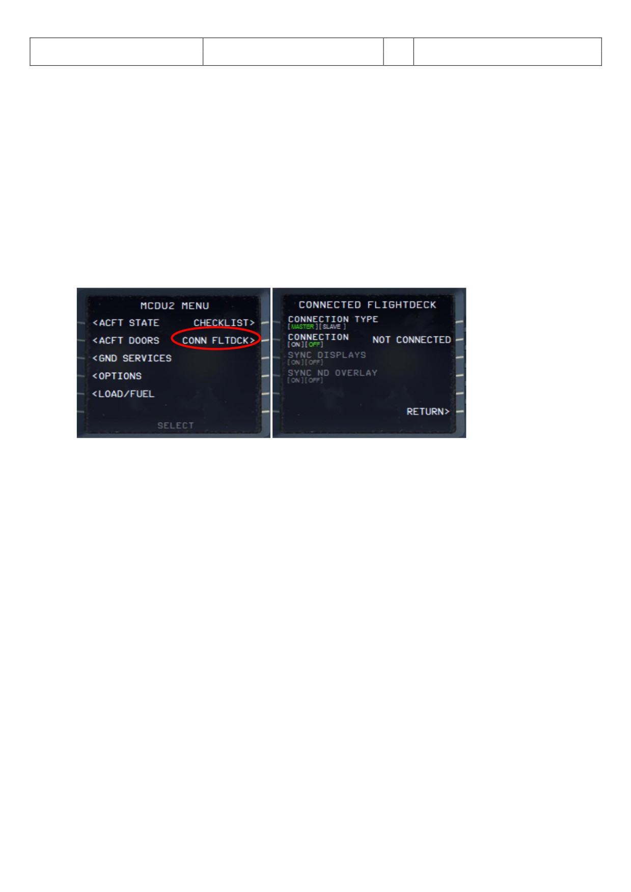
Checklist
The following Checklist Menu can be accessed via right MCDU - MCDU2 MENU.
Picture 48: Checklists Menu (page A)
This menu shows all available checklists and contains the following function:
The COCKPIT PREP checklist should be started (if blinking in orange) by clicking on the respective line
selection key = LSK3L. If it is marked in green (as on the picture above) it means it is already active.
Additionally a solution to skip a checklist item (if the copilot is not used) has been implemented (MCDU
CHECKLIST P GE LSK2L). The “white” message “SKIP ITEM” appears in future if there is a user action
necessary. If you do not know what to do or how to handle the item and you want to skip this checklist
item please just press LSK2L and the checklist jumps to the next item. But this facility is not available
during the APPROACH CL for flaps setting as well as during the complete FINAL CL because it would
make no sense.
Normally a call = checklist item is repeated various times until the right settings are made by the user.
But for “Barometric Check”, “Go-around- ltitude” and “Landing Memo” the call is repeated just three
times and then the checklist automatically jumps to the next item.
The blinking “info line” at the bottom of the screen shows what has to be done next and is identical with
the text of the info-bar (please see chapter 4.6.3 for details).
In such cases e. g. the checklist has to be started from the MCDU MENU - CHECKLIST the content of the
infobar also contains a hint which keypad key alternatively can be used to start the relevant checklist.
o Start "COCKPIT PREPARATION CL" using "1"
o Start “ENGINE ST RT WITH PUSHB CK CL” using "1"
o Start “ENGINE ST RT CL” using "2"
The checklist menu has two pages (A and B). To toggle between the two pages just push the MCDU
arrow buttons showing left or right.
The following checklists are available and linked to the chosen Aerosoft standard ACFT STATE e. g. not to any
saved user state.
Aerosoft
The Airbus A318/319/320/321 in FSX
Vol
06-01-07 Page 40
Airbus A318/319/320/321
Step-By-Step Tutorial
6
07 April 2015
Cockpit Preparation
Climb
Before Start
Cruise
Start with Pushback - or Start (w/0 pushback)
Descent Preparation
After Start
Descent
Taxiing
Approach
Before Takeoff
Final Landing
Takeoff
After Landing
After Takeoff
Parking
The detailed content of the checklists you will find in chapter 5.1 etc. (marked in “green”).
4.9
Connected Flight Deck
The following Connected Flight Deck Menu can be accessed via right MCDU - MCDU2 MENU.
Picture 49: Connected Flight Deck Menu
The feature will make it possible for to people to connect to each other and act as Captain and FO’s (Or PF and
PM). Details to this feature you will find in Vol 1 in chapter “Connected Flight Deck”.
CONNECTION TYPE
For the CFD to work, one of the users must be a master and the other a slave. This connection type must be
selected before turning connection on. The master has to start to initiate the connection and only there after
the slave can initiate his.
CONNECTION
Turning on will initiate connection, after turning on, turning it off have no effect.
SYNC DISPLAYS
With this option it is possible to synchronize the displays (ND range/mode etc and partially synchronized
altimeters) but with certain limitations.
SYNC ND OVERLAYS
With this option it is possible to synchronize terrain on ND and the weather radar panel, but not to
synchronize the weather itself.
4.10
Voice packs for PF and PM
For the checklists there are various voice packs for the Pilot Flying as well as the Pilot Monitoring available
(Standard, British, French, German and US). Those voice packs you want to use for your flight can be selected
Aerosoft
The Airbus A318/319/320/321 in FSX
Vol
06-01-07 Page 41
Airbus A318/319/320/321
Step-By-Step Tutorial
6
07 April 2015
using the Aerosoft Airbus A318/319/320/321 Configurator. More information on this you will find in the Vol1
InFSX document.
4.11
Saving all MCDU 2 settings
All in the MCDU2 made settings (except the use of the CHECKLIST- and the COPILOT-function) are saved e. g.
next time an Aerosoft Airbus A318/319/320/321 is loaded again you will start with all the settings from the
previous flight.
4.12
RAAS - Runway Awareness and Advisory System
Please see Vol 1 - InFSX EN (page 8) for details on this system. To adjust the RAAS settings with your FSX
scenery settings we recommend using Peter Dawson “MakeRwys.exe”.
Aerosoft
The Airbus A318/319/320/321 in FSX
Vol
06-01-07 Page 42
Airbus A318/319/320/321
Step-By-Step Tutorial
6
07 April 2015
5.
Tutorial Flight / Checklist and Procedures:
5.1
Basic Information - Setup
This tutorial flight describes all the phases of a flight from Innsbruck to Nice, from the “COLD DARK” situation
in Innsbruck to the landing at Nice, parking and securing the aircraft.
During the tutorial flight we are using the Aerosoft A318/319/320/321 procedure- and checklist which is based
on an original from Airbus. This list consists of a “running number” to identify the action to be performed and
in which panel, sub-panel the necessary knobs, switches and buttons can be found. The various panels
available and their terms are explained in chapter 2. If additional explanations for the actions are necessary
the row is marked in light yellow and the explanations can be found below the respective procedure- and
checklist using the “running number” as a reference.
gain using this tutorial the cockpit should be “COLD DARK”. fter switching the batteries 1 +2 to ON it should
look like in Picture 82. If there are still some lights ON switch off all those lights on the Overhead Panel.
Another option (which is necessary to use the Checklist- and Copilot function) is to load the plane and then go
to the right MCDU view, MCDU MENU / CFT ST TE and select “COLD DARK” state.
fter setting the aircraft to “COLD DARK” also the screen for the MCDU 2 is dark (because of no power). To
power the plane up (as well as the MCDU 2 screen):
Overhead Panel [F12] switch both batteries to ON section 4 (chapter 0)
Overhead Panel [F12] switch External Power to ON section 6 (chapter 0)
To power up the various screen (PFD, ND, upper and lower ECAM) please switch on the respective panel lights
(Glareshield #8 and EC M #4) as well as if necessary the “night” illumination using Pedestal #3.
lso the “CHECKLIST” and “COPILOT” function should already have been set to ON (=green). Please see
chapter 4.7. lso certain “limiters” (for approach speed and 250 knots) are included in the copilot (PM)
function please see chapter 4.6 for details.
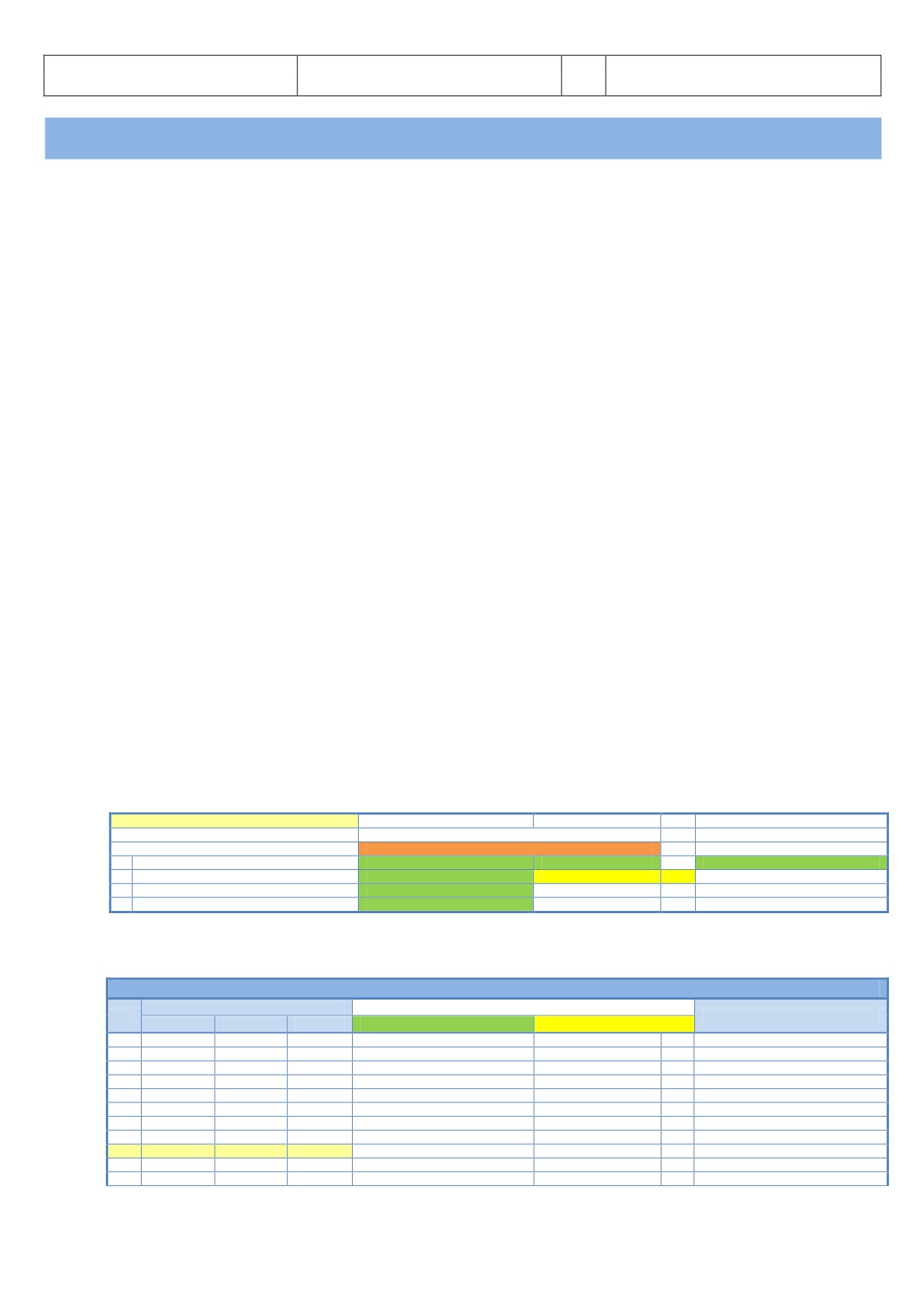
The different colors used in the following lists symbolize and explain the function:
Detailed description available - please see below -
Not supported by “Checklist” or “Copilot” function
Starting Conditions for Checklist
Starting Conditions for Checklist
1
Checklist
- Check only
Checklist item
Copilot (announcem./ check)
Ground announcement
2
Checklist / Copilot - Action done by Copilot -
Checklist item
Copilot (action)
CoP
(if option “Copilot” is selected)
3
Checklist / Copilot - ction to be done “manually” -
Checklist item
User (action) - necessary
4
Checklist / Copilot - ction to be done “manually” -
Checklist item
User (action)
Now start this tutorial with the “Basic Preparation Procedure” as described in chapter 5.2.
5.2
Basic Preparation Procedure (aircraft in COLD DARK state)
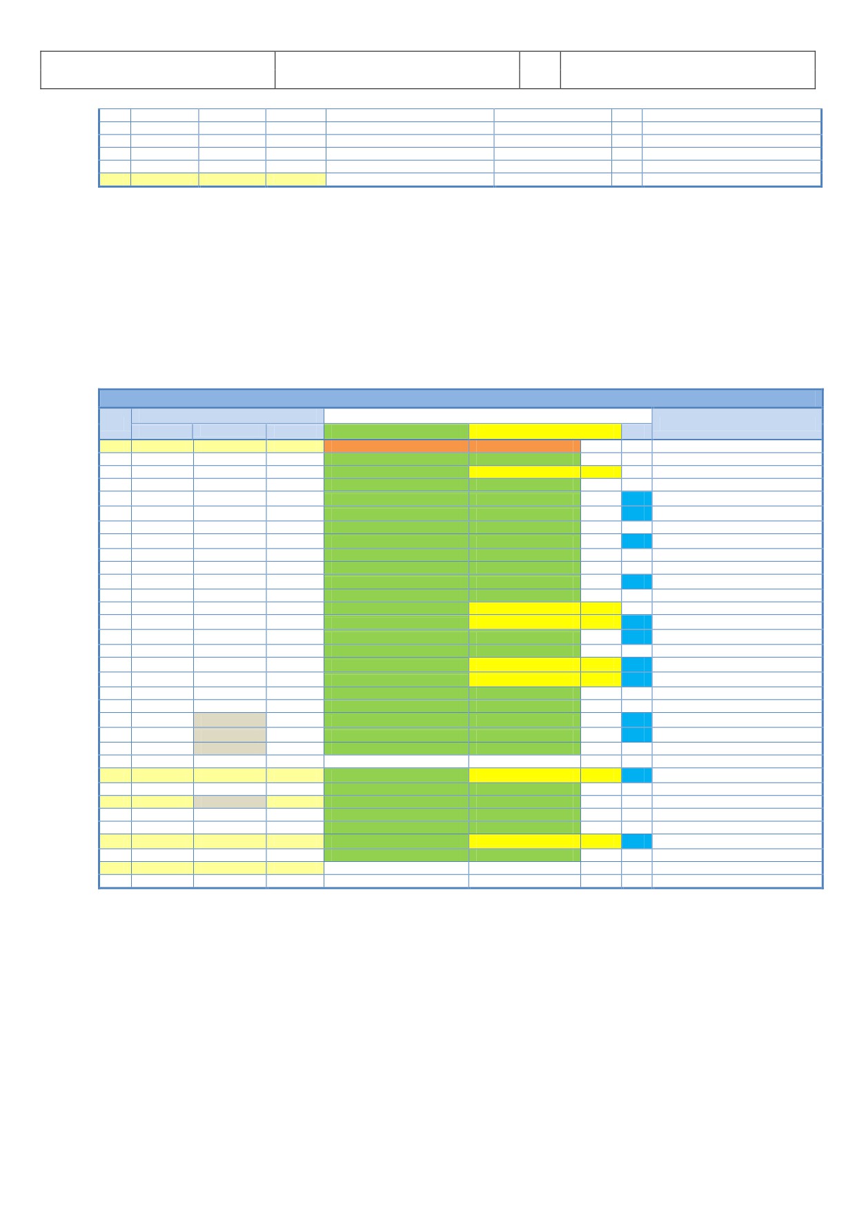
BASIC PREPARATION PROCEDURE
PANEL
ACTION
NO.
REMARK
TYP
PART (Name)
PART (No.)
PF (PILOT FLYING)
PM (PILOT MONITORING)
1
FUEL PLANNER ADV. METH.
PAX-, CARGO- and FUEL LOAD
SET and GEN. LOADSHEET
Please see chapter 4.1 for details
2
MCDU R
MAIN MENU
ACFT STATE
COLD DARK = LSKL1
PUSH
Should already been done
3
OVERHEAD
ELEC
3
BAT 1 + 2 (Batteries)
ON (BOTH)
Should already been done
4
OVERHEAD
ELEC
3
EXT POWER
ON
5
OVERHEAD
EXT. LIGHTS
9
EXT. LIGHTS (= Nav Lights)
ON
6
MAIN PANEL
PFD LIGHT
8
SWITCH
ON
7
MAIN PANEL
ND LIGHT
8
SWITCH
ON
8
ECAM
ECAM LIGHTS
4
SWITCH UPPER and LOWER
ON
9
PEDESTAL
INT. LIGHT
3
OVHD INTEG LT
ON
10
MCDU R
OPTIONS
SOUND
Cabin & Flight Crew, ATC
[ON] or [OFF]
As required - Color switches to green
11
MCDU R
OPTIONS
VIEWS
Panel & Wing View Bars and others
[ON] or [OFF]
As required - Color switches to green
Aerosoft
The Airbus A318/319/320/321 in FSX
Vol
06-01-07 Page 43
Airbus A318/319/320/321
Step-By-Step Tutorial
6
07 April 2015
12
MCDU R
OPTIONS
CHECKLISTS
CHECKL and COPILOT
ON (BOTH)
13
MCDU R
OPTIONS
CHECKLISTS
INFOBAR
ON
14
MCDU R
OPTIONS
CHECKLISTS
Various LIMITERS ( APP & 250 KNOTS) & ILS
[ON] or [OFF]
As required - Color switches to green
15
MCDU R
OPTIONS
CHECKLISTS
AES
[ON] or [OFF]
As required - Color switches to green
16
MCDU R
LOAD/FUEL
INIT LOADSHEET or manually enter data
16
MCDU R
LOAD/FUEL
LOAD to PLANE
LOAD INSTANT or separately
9. Cockpit Lights: Because sometimes the panels are quite dark - depending on the position of the sun -
please switch the cockpit light to BRT.
16. Load to Plane: Conditions to use these functions (except LOAD INSTANT) are:
All Load Requests: Engines = off and parking brakes or chocks are set
Pax boarding: Front or aft door is open
Cargo: Both cargo doors are open
For details please see chapter 4.7
5.3
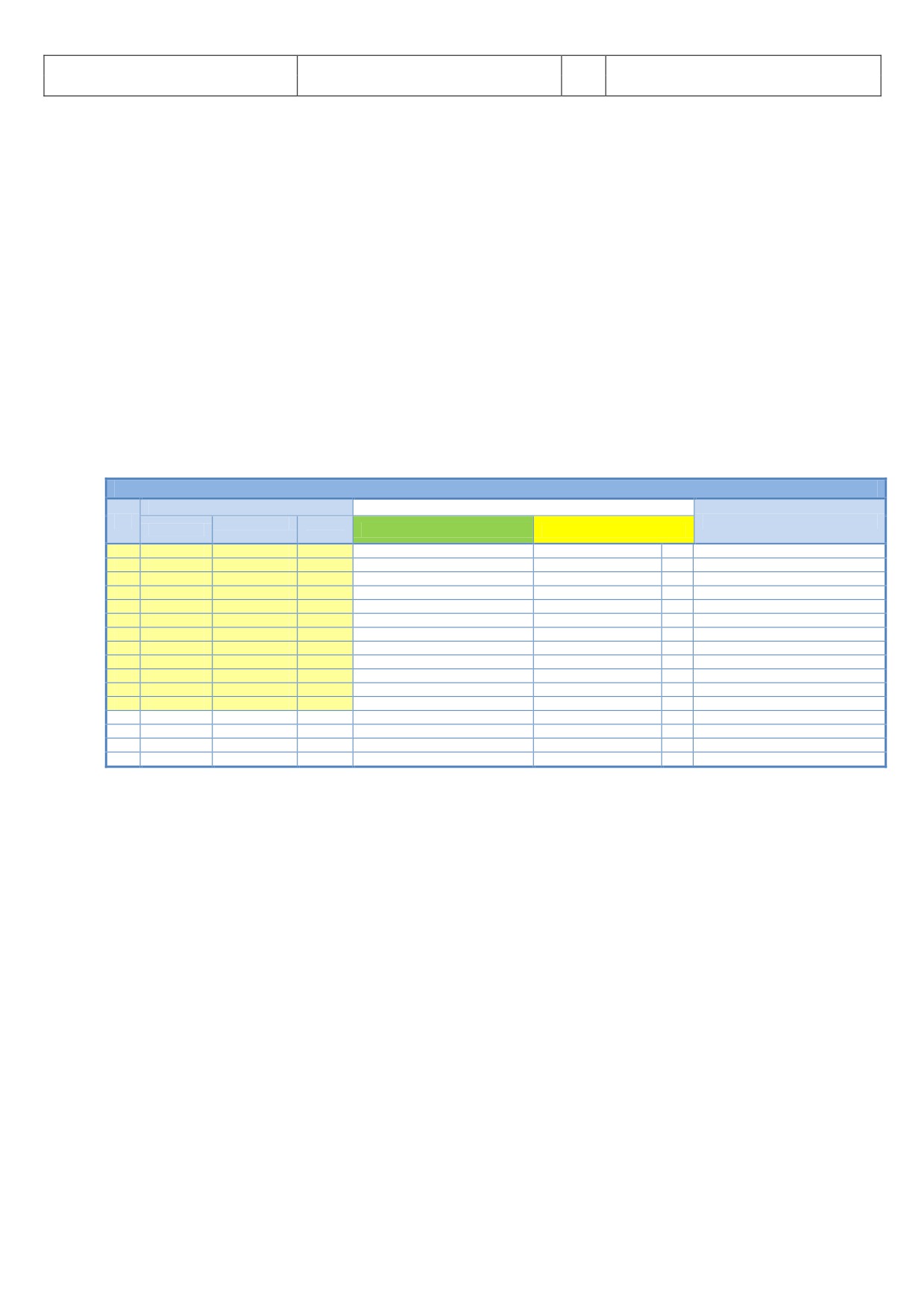
Cockpit Preparation
COCKPIT PREPARATION
PANEL
ACTION
NO.
REMARK
TYP
PART (Name)
PART (No.)
PF (PILOT FLYING)
PM (PILOT MONITORING)
TA
17
MCDU
MAIN MENU
CHECKLIST
A = PUSH LSK3L
PUSH
Start Checklist / Co-Pilot - if selected
18
OVERHEAD
ELEC
3
BAT 1 + 2 (Batteries)
CHECK ON (BOTH)
Cop
19
OVERHEAD
ELEC
6
EXT PWR (External Power)
ON
CoP
(if available - see MCDU MENU / DOORS)
20
OVERHEAD
EXT. LIGHTS
9
NAV. LIGHTS
CHECK ON
CoP
21
PEDESTAL
ENG
5
ENG MASTER 1 + 2
CHECK OFF
CoP
TA
22
PEDESTAL
ENG
5
ENG MODE SEL
CHECK NORM
CoP
TA
23
ECAM
LAND GEAR
2
LANDING GEAR LEVER
CHECK DOWN
CoP
24
PEDESTAL
P. BRAKE
7
PARKING BRAKE
CHECKED = OFF
CoP
TA
25
PEDESTAL
FLAPS
8
FLAPS LEVER
CHECK POSITION = 0
CoP
26
PEDESTAL
SP. BRAKE
6
SPEED BREAK LEVER
CHECK RETR. / DISARMED
CoP
27
PEDESTAL
THR LEVER
4
THRUST LEVERS
CHECK IDLE
TA
28
PEDESTAL
RADIO
1
TRANSPONDER MODE
CHECKED STANDBY
29
PEDESTAL
RADIO
1
RADIO CONTROL PANEL
ON
CoP
30
ECAM
ECAM
5
ECAM RECALL (RCL) BUTTON
PRESS
CoP
TA
31
MAIN PANEL
ANTI SKID
10
ANTI SKID
CHECK ON
CoP
TA
32
MAIN PANEL
EFIS
3
FLIGHT DIRECTOR
CHECK ON
CoP
33
OVERHEAD
SIGNS
12
EMERGENCY LIGHTS
ARM
CoP
TA
34
OVERHEAD
SIGNS
12
NO SMOKING SIGNS
ON
CoP
TA
35
OVERHEAD
SIGNS
8
WING & ENGINE ANTI ICE
CHECK OFF
Cop
36
OVERHEAD
PR.WI. HEAT
13
PROBE WINDOW HEAT
AUTO/OFF
37
OVERHEAD
AIR COND.
7
HOTAIR, ENG. BLEED L+R, PACKS L+R
CHECK ON
Cop
TA
(no white signs)
38
OVERHEAD
VENTILATION
14
BLOWER, EXTRACT, CAB. FANS
CHECK ON
TA
(no white signs - INOP not animated)
39
OVERHEAD
ELECTRIC
5
ENG. GENERATOR L+R
CHECK ON = FAULT
Cop
40
OVERHEAD
ELETRIC
5
APU GENERATOR
CHECK ON
(only if EXT. POWER is ON)
41
OVERHEAD
FUEL
2
ALL FUEL PUMPS
PRESS
CoP
TA
OFF should disappear
42
OVERHEAD
FUEL
2
ALL FUEL PUMPS = ON
CHECK
43
OVERHEAD
HYDRAULICS
1
ACCU BREAK PRESS: ELEC. PUMP
(ON)
See explanation
44
OVERHEAD
GPWS
15
GPWS: ALL SWITCHES
CHECK ON
Cop
(no white signs)
45
OVERHEAD
EFCS
16
EFCS: ALL SWITCHES
CHECK ON
Cop
(no white signs)
46
OVERHEAD
ADIRS
17
ADIRS (3x)
ON
CoP
TA
47
COCKPIT
EM.EQUIPMENT
ALL EQUIPEMT AVAILABLE AND OK
CHECK ON
Checklist complete
48
PEDESTAL
RADIO
1
SET FREQUENCIES
SET
If ATC is used
49
PEDESTAL
RADIO
1
ATC CLEARANCE
OBTAIN
If ATC is used
In the Cockpit Preparation CL after a Turnaround only the “blue” marked actions / procedures (T
) are used.
17.
Start Checklist: Alternatively you can also use “1” from the keyboard to start the checklist.
41.
Fuel Pumps: If no external power is used - in our tutorial we use external power # 19 - even after
switching the fuel pumps to ON the warning FAULT will remain, because they are not yet running.
F ULT will automatically disappear when the engines are running up. ll “white” lights should be
extinguished.
43.
HYDR. PUMPS: Only if accumulator pressure is below 500 PSI. The indication of the brake pressure
normally remains at zero.
Aerosoft
The Airbus A318/319/320/321 in FSX
Vol
06-01-07 Page 44
Airbus A318/319/320/321
Step-By-Step Tutorial
6
07 April 2015
46.
ADIRS: All three switches have to be set to NAV
48.
RADIO - SET FREQUENCIES - As the ATIS frequency for Innsbruck is 126.020 set the VHF1 frequency in
STBY/CRS to 126.025 (using the mouse wheel you can select on the outside knob the figures from 118.
to 136. and with the inside knob between .000 and .975). Then press on the green arrow to switch the
previously entered value from STBY into ACTIVE. After a short period you will hear the ATIS
information (weather, winds, pressure and runways in use etc.). After all necessary information has
been obtained press the switch again.
AES
The loaded “COLD DARK” aircraft state is with parking brakes = OFF and chocks = SET (parking brakes
GSX: are normally OFF to cool down the brakes). AES since version 2.26 recognizes “chocks = SET” and does
not require
“parking brakes
= ON” anymore. Open the AES window (CTRL+SHIFT+W) or GSX
(CRTL+F12) In AES just select the option “F5 - Request Boarding now” or in GSX “ 4 - Request
Boarding”.
5.4
FMGS / MCDU - Data Insertion
Always use the following sequence for the data insertion into the MCDU: INIT A page, F-PLN, RAD NAV, INIT B
page, PERF = IFRIP.
COCKPIT PREPARATION - FMGS/MCDU DATA INSERTION
PANEL
ACTION
NO.
PART (Name)
PART
REMARK
TYP
PF (PILOT FLYING)
PM (PILOT MONITORING)
(No.)
50
MCDU
INIT 1
DEP and DEST AIRPORT
ENTER
LOWI/LFMN
51
MCDU
INIT 1
ALIGN IRS
PRESS
52
MCDU
INIT 1
FLT NBR (Flight Number)
ENTER
Par example =LH319
53
MCDU
INIT 1
COST INDEX
ENTER
30
54
MCDU
INIT 1
CRZ FL (Cruise Flight Level)
ENTER
=310 (31.000 feet)
55
MCDU
F-PLAN
FLIGHTPLAN
ENTER
56
MCDU
RAD NAV
ENTER ADF1 FREQUENCY
ENTER
RTT
57
MCDU
INIT 2
BLOCK
ENTER
6.8
58
MCDU
INIT 2
ZFWCG/ZFW
CHECK
25.0/49.5 - speeds and altitude are calculated
59
MCDU
PERF-TO
FLAPS / THS
ENTER
2/
60
MCDU
PERF-TO
FLEX TO TEMP
CHECK
61
MCDU
PERF-TO
V1, VR and V2
CHECK
89/120/124
62
MCDU
PERF-CLIMB
DATA
CHECK
63
MCDU
PERF-CZR
DATA
CHECK
64
MCDU
PERF-DES/APPR
DATA
CHECK
65
MCDU
PERF-GO ARD
DATA
CHECK
Open the MCDU. If the data or menu page is displayed; use the INIT button so that page INIT A opens (INIT B
only can be opened if the engines are not running). The data input can either be done using the scratchpad or
the PC keyboard. To use the PC keyboard please just “left” click on the grey field beside ‘1’ on the scratchpad.
The change will be confirmed “KEYBO RD INPUT ON”. To change back to the MCDU scratchpad “right” click on
the same spot again.
50. FROM/TO: Enter LOWI/LFMN into the scratchpad and then press LSK1R. You will see that another page
automatically opens displaying the available company routes (LOWILFMN01). As we want to get
acquainted entering a flightplan ourselves we will not use this function. So just press the respective LSK
for RETURN.
XX. ALTN: Enter LFML as an alternative airport for Nice.
51. ALIGN IRS: Please press LSK 3R to start the IRS (Inertial Reference System). Aligning the IRS will take 6
minutes and the status is displayed on the E/WD in the status section. If the IRS is aligned the PFD and
ND change to the standard view.
XX. CO RTE - ALT/CO RTE: Leave CO RTE empty and ALT/CO RTE with NONE because we will currently not
use this function e. g. to use a predefined flight plan from Nice to an alternative airport for it. Please see
chapter 1and 0 for details on this function.
52. FLT NBR: Please enter the flight number using the MCDU keyboard - in our case DLH319 (for Lufthansa)
Aerosoft
The Airbus A318/319/320/321 in FSX
Vol
06-01-07 Page 45
Airbus A318/319/320/321
Step-By-Step Tutorial
6
07 April 2015
- into the scratchpad and then use LSK 3L to cut and paste the data into the field FLT NBR.
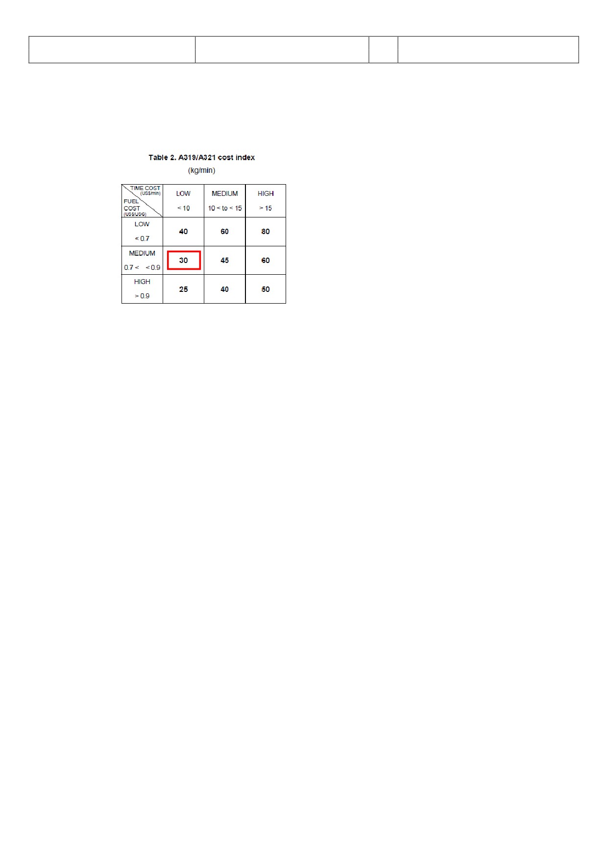
53. COST INDEX: The Cost Index determines the speed used for climb, cruise and descent if managed speed
is used. Please enter using the MCDU keyboard a value of 30 and then use LSK 5L to cut and past the
value into the field COST INDEX. The cost index for fuel and maintenance of 30 is a low time cost and
medium fuel cost value (please see table below).
Picture 50: Table Cost Index
54.
CRZ FL: In our case it is 31.000 feet (so enter 310) and the outside temperature for this flight level then
automatically will be calculated = -47 degrees.
55.
F-PLAN: We will use the flight plan as explained in chapter 3.9 (LOWI - INN UM726 BZO UM984 EVANO
UZ185 BORDI - LFMN). Please use the F-PLAN button of the left MCDU to change to the F-PLAN page.
Push LSK1L (next to LOWI)
Push LSK1L (next to DEPARTURE)
Select takeoff runway: In our case we will use 08
Select SID = RTT2J by browsing (use the button with arrow showing up) and then push the respective LSK L)
Insert SID into temporary flightplan = LSK6R
Browse (using the button with arrow showing up) to RTT and push the respective LSK L next to RTT
Enter INN into the scratchpad and push the respective LSK 3R next to NEXT WPT
Select INN = LSK1L
Browse (using the button with arrow showing up or down) to INN and push the respective LSK L next to INN
Select AIRWAYS = LSK5R
Enter UM726 into the scratchpad and push LSK1L
Enter BZO into the scratchpad and push LSK1R
Enter UM984 into the scratchpad and push LSK2L
Enter EVANO into the scratchpad and push LSK2R
Enter UZ185 into the scratchpad and push LSK3L
Enter BORDI into the scratchpad and push LSK3R
Insert flightplan into temporary flightplan = LSK6R
Browse (using the button with the arrow showing up) until you see BORDI and F-PLAN DISCONTINUITY
Push the CLR button - CLR will appear on the scratchpad
Push the respective LSK L to F-PLAN DICONTINUITY (and it will be cleared)
Select LFMN = Push LSK6L
Select ARRIVAL = Push LSK1R
Select landing runway: In our case we will use ILS04L. Browse (using the button with arrow showing up) to ILS04L
Select STAR = BORD6C by browsing (use the button with arrow showing up) and push the respective LSK L)
Select VIA (LSK2L) = NERAS (LSK4L)
Enter STAR into temporary flightplan = LSK6L
Enter Temporary Flightplan = LSK6R
Browse (use the button with arrow showing up) and look lines showing F-PLAN-DISCONTINUITY
If there are one, push the button CLR on the scratchpad and then the LSK L beside F-PLAN-DISCONTUNUITY
The complete flightplan then should look approximately as follows (speed and flight level are the
actual flight values):
Aerosoft
The Airbus A318/319/320/321 in FSX
Vol
06-01-07 Page 46
Airbus A318/319/320/321
Step-By-Step Tutorial
6
07 April 2015
DIST.
(NM)
Actual
Actual
NO.
ID
NAME
VIA
CSTR
to next WP
SPEED
ALT. (FT)
1
LOWI08
INNSBRUCK
C079°
5
124
1.900
2
INTCPT
C066°
2
250
5.700
3
AB
ABSAMS
RTT2J
4
250
7.600
4
(LIM)
1
250
10.000
5
DOEJ
RTT2J
6
250
10.800
+4.800 feet
6
OEJ07
RTT2J
4
294
13.500
+6.700 feet
7
9500
RTT2J
5
294
17.300
+9.500 feet
8
RTT
RATTENBURG
RTT2J
25
294
17.300
9
INN
INNSBRUCK
UM726
15
294
31.000
10
T/C
UM726
0
294
31.000
11
BRENO
BRENNER
UM726
12
294
31.000
12
OGEPI
UM726
20
294
31.000
13
BZO
BOLZANO
UM726
21
294
31.000
14
RENTA
UM984
20
294
31.000
15
ATPED
UM984
15
294
31.000
16
LUSIL
UM984
38
294
31.000
17
RODRU
UM984
33
294
31.000
18
EVANO
UM984
65
294
31.000
19
ENOBA
UZ185
21
294
31.000
20
T/D
UZ185
8
294
31.000
21
BORDI
BORDI237°
17
294
28.800
22
NIZ/09
C143°
12
294
21.500
23
MIKRU
BORD6C
21
294
16.600
24
PIRAM
BORD6C
1
250
9.100
25
INTCPT
C112°
7
250
8.800
26
AZR35
35AZR
4
250
6.200
27
NERAS
NERAS
4
250
4.000
4.000 feet
28
AZR26
NERAS
2
250
4.000
29
INTCPT
C298°
35
250
4.000
30
(DECEL)
3
200
4.000
31
NIZ27
27NIZ
4
179
4.000
200 knots
32
NI17
C043°
5
179
4.000
33
NI122
NERAS
4
179
4.000
4.000 feet
34
NI77
3
141
2.500
2.500 feet
35
NI51
5
134
1.600
1.600 feet
36
LFMN04L
0
Total :
448 NM
Picture 51: Detailed Flight Plan LOWI - LFMN
Waypoints like 4 (LIM), 10 (T/C), 20 (T/D), 25 (INTCPT) and 30 (DECEL) are at this stage not yet calculated
by the MCDU - will be inserted automatically after the MCDU programming is complete.
The waypoints after #36 LFMN04L are automatically inserted because in case of “landing abort” those
are the next waypoints you should head to and to await new instructions by the ATC.
The flight plan itself i.e. departure airport LOWI, complete route and arrival airport LFMN (but except
departure runway, SID, STAR/TRANS and arrival runway) is already previously saved as a company route.
You can load it using the MCDU and the INIT A page entering into the scratchpad LOWILFMN01 and then
using LSK1L. Please note that the loading will take some time because the whole navigation DB has to be
searched for the respective data. If you use this option then after loading just add departure runway,
SID, arrival runway and STAR/TRANS.
56.
RAD NAV: Optional and not necessary because we are using “Managed Mode” for our flight: Enter RTT
into the scratchpad and then press LSK5L. To activate ADF please go to the 2.1.5 EFIS CONTROL PANEL
#7 and set the left switch to ADF.
XX.
INIT PAGE B or 2: Please press INIT and then use the button with the arrow showing right to change to
the INIT page 2 (INIT page 2 or B only can be opened if the engines are not running)
57.
BLOCK: Please enter 6.8 in the scratchpad and then press LSK 2R
58.
ZFWCG/ZFW: ZFWCG and ZFW are automatically calculated and displayed. If you want to change the
first value ZFWCG all you have to do is enter the new value and press the appropriate line select key, to
overwrite the leftmost value. The relation / calculation between TOW, Centre of Gravity in % of the MAC
(mean aerodynamic chord) and THS are content of the Load- and Fuelplanner (Advanced Mode).
XX.
PERF PAGE: Please change to the Performance Page by pressing the respective button on the MCDU.
59.
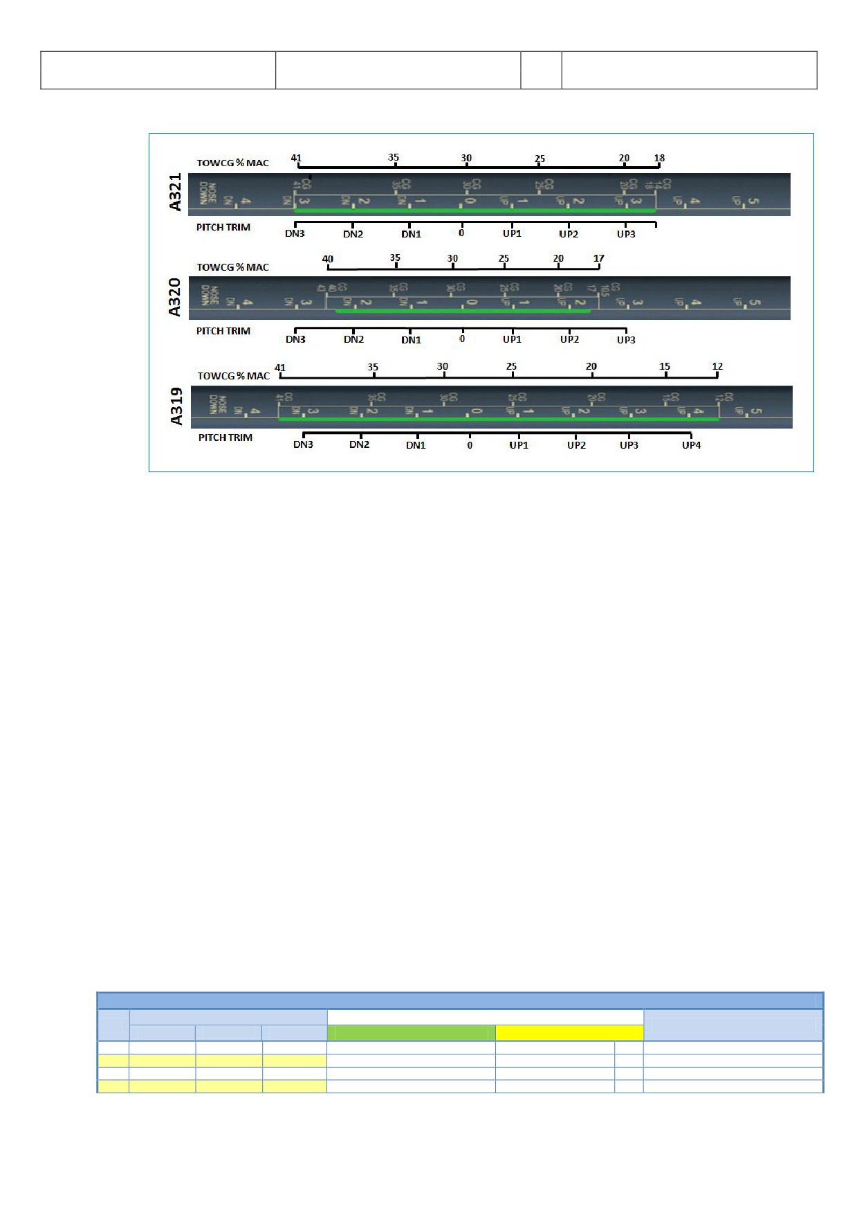
FLAPS/THS = Trimmable Horizontal Stabilizer: Please see below a picture showing the relation between
Aerosoft
The Airbus A318/319/320/321 in FSX
Vol
06-01-07 Page 47
Airbus A318/319/320/321
Step-By-Step Tutorial
6
07 April 2015
CG and THS.
Picture 52: CG (centre of gravity)/ THS
Make the necessary load- and fuel-calculations using the Fuelplanner. For our flight this would be a
value of 28 TOW %MAC (also content of the LOADSHEET) and a proposed trim of UP0.1.
As in our case we will use FLAPS 2 for the takeoff please enter “2/UP0.1” into the scratchpad and then
press LSK 3R so that the value is cut and pasted into the field FLAPS/THS (if the proposed THS value is 0.0
then please enter /UP0.0). But please remember the input of those values does not mean that at the
same time the real flaps- and trim setting are automatically made (only in case the Copilot- function is
set to ON). Otherwise you have to set the flaps position and trim manually. The exact trimming value is
displayed on the lower ECAM F/CTL page = PITCH TRIM.
60.
FLEX TO: The value is automatically calculated and displayed based on the selected flaps setting for
takeoff. If you want to change the value, just overwrite the content of this field. Because we will use
Flaps 2 and the runway at LOWI is quite short no value for FLEX takeoff is automatically calculated e. g.
MAN TOGA is proposed.
XX.
ENG OUT ACC: We leave the engine out / acceleration altitude as proposed by the MCDU (Ground level
plus 1500 = 3407 Feet).
61.
V1, V2 and VR: The values are automatically calculated and displayed. If you want to change those
values, just overwrite the content of the fields. Please note that those various speeds are only calculated
after FLAPS are entered (#57)
XX.
TRANS ALT: The transition altitude for Innsbruck is 11000 feet - so manually enter this value.
XX.
THR RED / ACC: We leave the thrust reduction / acceleration altitude as proposed by the MCDU (Ground
level plus 1500 Feet).
XX.
Performance Pages: Please also check the other PERF pages (CLB, CRZ, DES and APPR) by using LSK6R or
LSK6L. Make sure all parameters are OK. Especially the Cost Index should be checked, which determines
the speed used for climb, cruise and descent if managed speed is used
5.5
Cockpit Preparation - Part 2
COCKPIT PREPARATION - Part 2
PANEL
ACTION
NO.
REMARK
TYP
PART (Name)
PART (No.)
PF (PILOT FLYING)
PM (PILOT MONITORING)
66
EFIS
FD / ILS
3
Button: LS
OFF
67
EFIS
ND MOD/RGE
5 & 6
ND mode and range
SET
Mode: ARC / Range 10
68
EFIS
ADF/VOR
7
VOR / ADF select
AS REQUIRED
69
FCU
ALTITUDE
3
First Altitude
SET TO 12.000 Feet
>than THR RED altitude
Aerosoft
The Airbus A318/319/320/321 in FSX
Vol
06-01-07 Page 48
Airbus A318/319/320/321
Step-By-Step Tutorial
6
07 April 2015
70
FCU
FCU
1 to 4
DASH-BALL-DASH-BALL-ALT-BALL-DASH
CHECK
71
ECAM
ECAM
1
STATUS
CHECK
72
PEDESTAL
RADIO
1
ATC - FREQUNCY
SET
If ATC is used
73
PEDESTAL
RADIO
1
ATC CLEARANCE
OBTAIN
If ATC is used
74
GLARESHIELD
ND-DISPL.
2
IRS ALIGN
CHECK
75
MCDU
F-PLAN
F-PLAN PAGE
SET
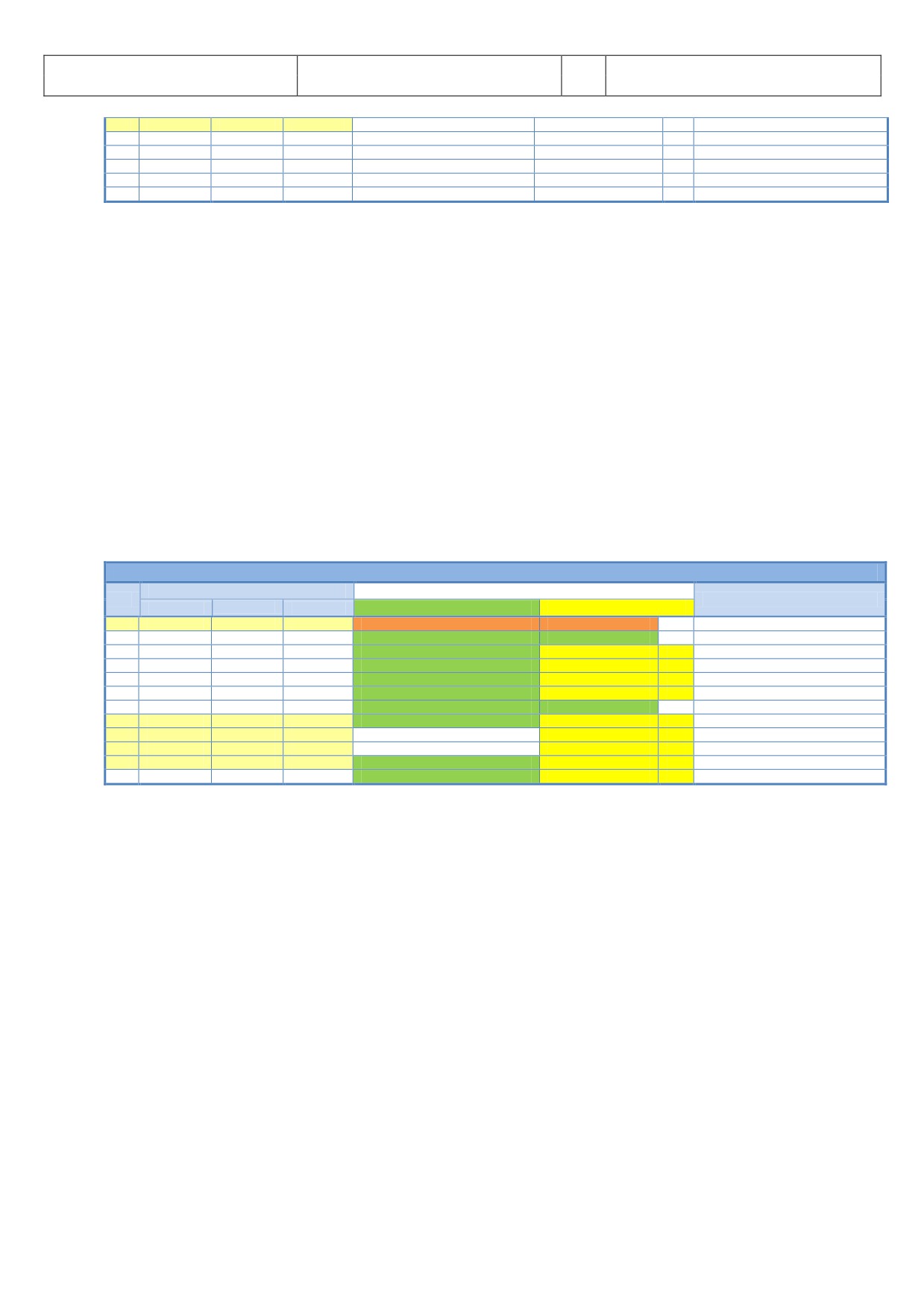
67.
ND mode and range: Set ND mode during takeoff to ARC and range to 10.
69.
First Altitude: On the FCU (Flight Control Unit) - Altitude - using the respective knob please set the
1st to be reached altitude at 12.000 Feet. This value has to be in any case higher than the Thrust
Acceleration Altitude (in our example 3407 Feet). If this is the case then a ball appears to the right of
the altitude entered which means that the aircraft will fly in “managed mode” until this altitude is
reached. Please confirm the entry by pushing the knob. Then it is “confirmed” and can be seen as a
“blue” value on top of the “ ltitude Indicator” on the PFD.
If you forgot to enter a “First ltitude” or if you started with the T XI or T KEOFF aircraft state the
copilot (if used) automatically sets the first altitude to 7.000 feet during TAXI or before TAKEOFF.
70.
FCU-Mode: Push FCU SPD and HDG knob so that the displays show SPD=“---●”
HDG=“---●” LT=12000●”and “-----” e.g. SPD and HDG are in “managed mode”
AES
Open the AES (CTRL+SHIFT+W) or GSX window (CRTL + F12). In AES select the option “F6 - Prepare for
GSX: Departure” and then select the option “F1 - Yes, I need Pushback please, prepare now, wait for start
request” In GSX select: “4 - Prepare for Pushback and Departure”.
5.6
Before Pushback and Start
BEFORE PUSHBACK OR START
PANEL
ACTION
NO.
REMARK
TYP
PART (Name)
PART (No.)
PF (PILOT FLYING)
PM (PILOT MONITORING)
76
MCDUw
MAIN MENU
ACFT DOORS
CLOSE ALL DOORS
PUSH
Start Checklist / Co-Pilot - if selected
77
MCDU R
MAIN MENU
ACFT DOORS
ALL WINDOWS AND DOORS CLOSED
CHECK
CoP
78
OVERHEAD
APU
10
APU MASTER and START
ON
CoP
START= available 10 sec after MASTER
79
OVERHEAD
APU
10
APU BLEED = ON
ON
CoP
80
MCDU
ELEC
6
EXT PWR
OFF
CoP
81
OVERHEAD
SIGNS
12
SEAT BELT SIGNS / NO SMOKING = ON
ON
CoP
For Seat Belts also AUTO is OK
82
PEDESTAL
THR LEVER
4
LEVERS
CHECK IDLE
83
PEDESTAL
P. BRAKE
7
PARKING BRAKE
SET to ON
CoP
FSX: CTRL + . (period)
84
MCDU2
MAIN MENU
GND SERV.
TRAFFIC CONES
REMOVE
CoP
85
MCDU2
MAIN MENU
GND SERV.
WHEEL CHOCKS
REMOVE
CoP
86
EFIS
AP SETTING
2
BARO REF
SET / X CHECK (Read out)
CoP
87
OVERHEAD
EXT. LIGHTS
9
BEACON
ON
CoP
Checklist complete
76.
DOORS / START CL: Closing left side passenger doors as well as cargo doors are blocked when pax
boarding and cargo loading (MCDU2 LOAD/FUEL MENU) is ongoing. Checklist only starts if pax
boarding and cargo loading (MCDU2 LOAD/FUEL MENU) is completed = are green.
83.
PARKING BRAKE: The parking brakes were OFF when the “COLD DARK” aircraft state was loaded.
Now they are set to ON.
84.
TRAFFIC CONES: Are automatically removed without call.
85.
WHEEL CHOCKS: Are automatically removed without call
86.
BARO REF: s we are flying with “Fair Weather” it means that in Innsbruck there will be no surface
winds and for takeoff the runway 08 is in use. The air pressure currently is 1013 hPa and we have a
temperature of 15 degrees C. s this is the “standard value” nothing has to done. If the air pressure is
different the Copilot will automatically set the right value.
5.7
Engine Start
AES: Open the AES window (CTRL+SHIFT+W) or GSX (CRTL+F12). In AES select the option “F2 - Start
Pushback now - Nose to Right” or in GSX = 1 - Nose right / Tail left.
During pushback you can start the engines according to #97 - #101. The settings will be confirmed by
the Pilot and the Copilot. When pushback has been finished set parking brake to ON and proceed with
Aerosoft
The Airbus A318/319/320/321 in FSX
Vol
06-01-07 Page 49
Airbus A318/319/320/321
Step-By-Step Tutorial
6
07 April 2015
chapter 5.8 .
If no pushback is required then please use the respective AES / GSX function and set the checklist AES
/ GSX PUSH function (please see 4.6.3) to NO. After AES / GSX has finished its procedure continue and
select the “Engine Start w/o Pushback” checklist and start it (5.7.2.). The reason is that AES / GSX are
closed programs and we cannot get any information when to start the Engine Start checklist if there is
no “moving” aircraft.
Engines can either be started during or after pushback (if necessary). Therefore also 2 different checklists are
available in the MCDU MENU - Checklists. Please select the one you want to use by clicking on the respective
LSK.
5.7.1 Engine Start with Pushback
ENGINE START - with pushback
PANEL
ACTION
NO.
REMARK
TYP
PART (Name)
PART (No.)
PF (PILOT FLYING)
PM (PILOT MONITORING)
88
MCDU
MAIN MENU
CHECKLIST
SELECT: “ST RT WITH PUSH” = LSK5L
Starts next Checklist / Co-Pilot - if selected
89
MCDU right
SELECT TAXIWAX DIST and PB DIRECTION
SET
90
MCDU right
START PUSHBACK
START
91
„Flight Deck to Ground“
GROUND: „Go ahead“
92
„We have TC clearance“
GROUND: „Roger“
93
„Confirm ground equipment = clear”
GROUND: “Clear”
94
“Starting pushback”
GROUND: “Roger”
95
PEDESTAL
P. BRAKE
7
PARKING BRAKE = OFF
SET to OFF
FSX: . (period)
96
GROUND: “OK. Starting Pushback”
97
PEDESTAL
ENGINE
5
ENG MODE SEL
IGN START
98
PEDESTAL
ENGINE
5
MASTER SW 2
ON
99
MAIN PANEL
E/WD
5a
No. 2 RUNNING UP
CHECK
100
PEDESTAL
ENGINE
5
MASTER SW 1
ON
Engine 2 N1 > 20%
101
MAIN PANEL
E/WD
5a
No. 1 RUNNING UP
CHECK
102
When in Position: Stop Pushback
STOP (SHIFT + P)
103
GROUND: „Pushback complete”
104
PEDESTAL
P. BRAKE
7
PARKING BRAKE
ON
FSX: CRTL +.(period)
105
GROUND: “Have a good flight” - CL complete
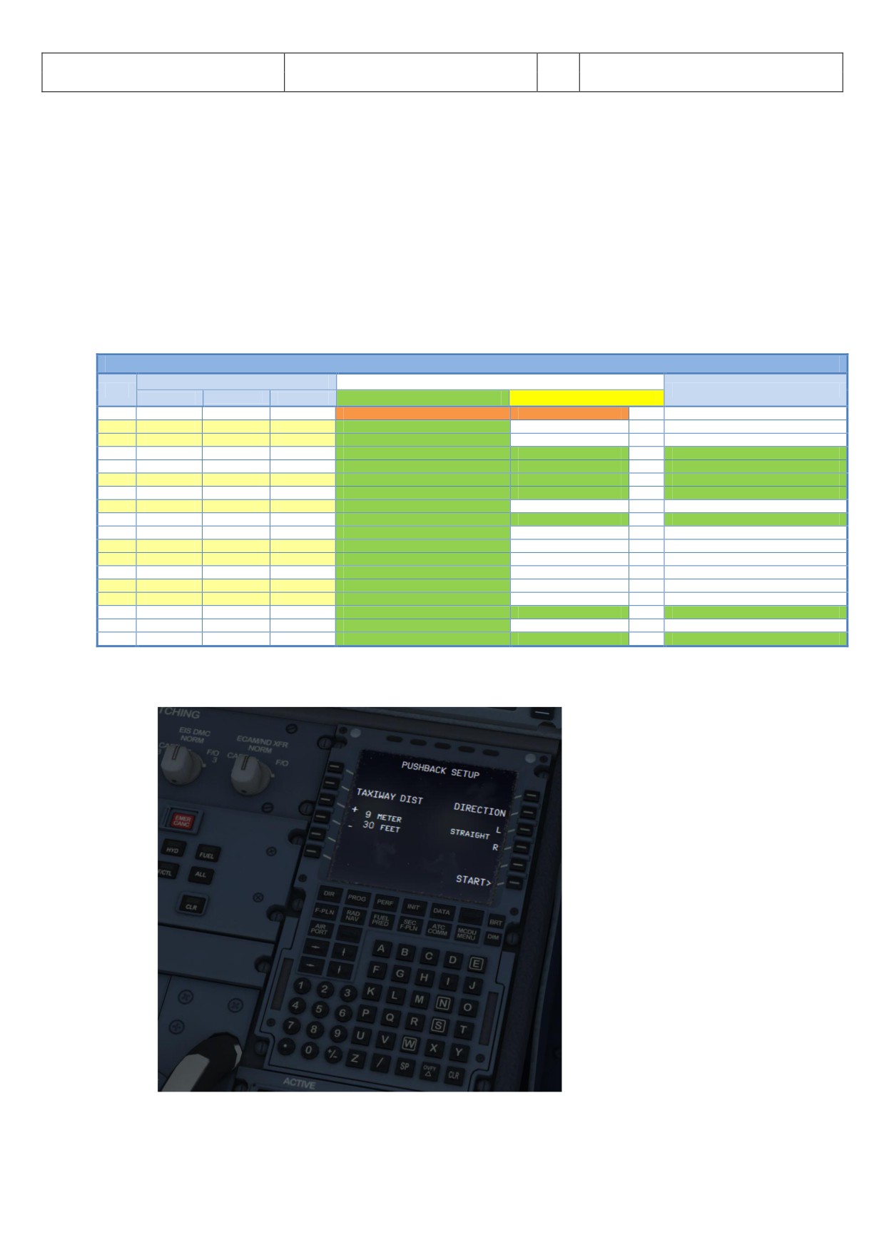
89.
Taxiway Distance and Pushback Direction: After the checklist has been started automatically the
following right MCDU menu opens
Picture 53: Pushback Gauge
Aerosoft
The Airbus A318/319/320/321 in FSX
Vol
06-01-07 Page 50
Airbus A318/319/320/321
Step-By-Step Tutorial
6
07 April 2015
Please set the distance to the taxiway (using LSK 3L or LSK 4L) as well as the pushback direction (using
LSK 3R or LSK 4R) in our case (S Parking 8 in LOWI) = 9 m and 90 degrees left. To set the correct value
you also can use the mouse scroll wheel.
The feature uses the FSX basic pushback function and is it a little bit "enhanced". The FSX function
consists of a time part "straight" and the turn part. The minimum time FSX uses / needs for “straight”
is app. 7-9m (based on aircraft model used) e. g. time is converted into distance. Additionally to that
the distance for the turn itself comes on top - a medium value for a 90° turn is app. 50m. But this
distance varies based on angle used and size of the plane e. g. for the A318 it is much smaller than for
the A321. But if needed you can always stop the pushback by using SHIFT+P.
90.
Start Pushback: Push “ST RT” (LSK 6R) and the pushback starts͙.. There is no need to stop the
pushback - it automatically will stop when the previously set position is reached.
93.
Parking Brakes: Do not touch the parking brakes earlier than asked by the ground service crew! Only
then release the brakes.
98.
Engine Start: After setting the Engine Mode Selector to IGN START as well setting the Engine Master
Switch to ON, you can check on the EWD that the FADEC (Full Authority Digital Engine Control) have
turned on because the amber information is replaced by active displays.
CFM engines spool up to around N2 24% and then light up and produce an EGT rise. Normally this
takes some 15 sec max. But if IAE engines are installed it takes another 15 sec before the engine lights
up because IAE implemented an 30 sec "blow through" / dry crank sequence to get rid of any
remaining fuel/oil before starting the actual engine start sequence.
99.
Engine stabilized: The set limits are
101.
CFM: N1: 18.5 % N2: 64.0% and EGT: 350°C
IAE: EPR 1.010, N1: 21.0%, N2: 57.0% and EGT: 410°C
102.
Stop Pushback: To stop the pushback it is not necessary to do anything. The pushback will stop and
the defined position (see settings # 89). If needed you can always stop pushback by using SHIFT+P.
5.7.2 Engine Start without Pushback
ENGINE START
PANEL
ACTION
NO.
REMARK
TYP
PART (Name)
PART (No.)
PF (PILOT FLYING)
PM (PILOT MONITORING)
106
MCDU
MAIN MENU
CHECKLIST
SELECT: “ST RT” = LSK6L
Starts next Checklist / Co-Pilot - if selected
107
„Flight Deck to Ground“
GROUND: „Go ahead“
108
„We have TC clearance“
GROUND: „Roger“
109
„Confirm ground equipment = clear”
GROUND: “Clear”
110
„Starting engines“
GROUND: „Roger“
111
PEDESTAL
ENGINE
5
ENG MODE SEL
IGN START
112
PEDESTAL
ENGINE
5
MASTER SW 2
ON
113
MAIN PANEL
E/WD
5a
No. 2 RUNNING UP
CHECK
114
PEDESTAL
ENGINE
5
MASTER SW 1
ON
Engine 2 N1 > 20%
115
MAIN PANEL
E/WD
5a
No. 1 RUNNING UP
CHECK
116
“Both Engines running”
GROUND: „Roger“
117
GROUND: “Have a good flight” - CL complete
112. Engine Start: After setting the Engine Mode Selector to IGN START you can check on the EWD that the
FADEC (Full Authority Digital Engine Control) have turned on. The amber crosses will disappear when
setting the Engine Mode Selector to IGN/START. Only the N1 and N2 will have amber crosses now
which will disappear when you select the Engine Master to one.
CFM engines spool up to around N” 22% and then light up and produce an EGT rise. But if IAE engines
are installed observe the EGT after 30 sec. because IAE implemented an 30 sec "blow through" / dry
crank sequence to get rid of any remaining fuel/oil before starting the actual engine start sequence.
5.8
After Engine Start
AFTER ENGINE START
PANEL
ACTION
NO.
REMARK
TYP
PART (Name)
PART (No.)
PF (PILOT FLYING)
PM (PILOT MONITORING)
118
ENGINE 1 & 2 are running for 15 sec
Start Checklist / Co-Pilot - if selected
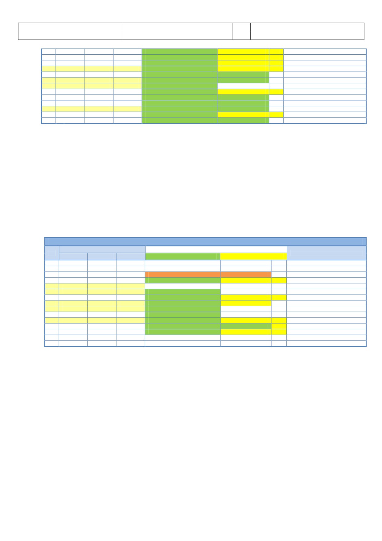
Aerosoft
The Airbus A318/319/320/321 in FSX
Vol
06-01-07 Page 51
Airbus A318/319/320/321
Step-By-Step Tutorial
6
07 April 2015
119
PEDESTAL
ENGINE
5
ENG MODE SEL
NORM
CoP
120
OVERHEAD
APU
10
APU BLEED
OFF
CoP
121
OVERHEAD
APU
10
APU MASTER SW
OFF
CoP
122
PEDESTAL
SPEED-BR.
6
GROUND SPOILERS
ARM
CoP
Mouse click: right
123
PEDESTAL
RUDDER
4
RUDDER TRIM
SET to 0 degree
CoP
124
PEDESTAL
PITCH
4
PITCH TRIM
SET to THS Value
125
AILERON, ELEVATOR and RUDDER
CHECK ALL 6 POSITIONS
126
PEDESTAL
FLAPS
8
FLAPS
SET to 2
CoP
FSX: F7
127
OVERHEAD
ANTI-ICE
8
ENG ANTI ICE (1 &2)
ON / OFF
128
OVERHEAD
ANTI-ICE
8
WING ANTI ICE
ON / OFF
129
ECAM
ECAM
1
ECAM STATUS
CHECK
130
ECAM
ECAM
1
ECAM DOOR PAGE
CHECK
CoP
131
HAND SIGNAL RECEIVED
Checklist complete
122. GRD SPOILERS: In order to be able to arm the spoilers without extending them, please move the thrs
slightly out of idle. The problem is that FSX uses Boeing style spoilers, which extend when armed and
the thrust levers are in idle position. Another option is to click on the spoiler arm using the right
mouse button.
124. PITCH TRIM: Copilot sets value according to the THS value (MCDU - PERF page)
125. FLIGHT CONTROLS: Turn the sidestick to all positions e. g. FULL LEFT, FULL RIGHT, NEUTRAL, FULL UP,
FULL DOWN, NEUTRAL, RUDDER FULL LEFT and RUDDER FULL RIGHT (only if “AUTORUDDER” i. e. the
option in the right MCDU - FLIGHT OPTIONS is not set to ON). Each required position / check is
mentioned in the INFOBAR and the various checks are orally confirmed.
129. ECAM STATUS: If the CLR button is ON it is necessary previously to confirm a “warning message”.
5.9
TAXI
TAXI
PANEL
ACTION
NO.
REMARK
TYP
PART (Name)
PART (No.)
PF (PILOT FLYING)
PM (PILOT MONITORING)
132
PEDESTAL
RADIO
1
TAXI CLEARENCE
OBTAINED
If ATC is used
133
PEDESTAL
P. BRAKE
7
PARKING BRAKE
OFF
FSX: . (period)
134
GS> 10 Knots
Start Checklist / Co-Pilot - if selected
135
OVERHEAD
EXT. LIGHTS
9
NOSE LIGHT
TAXI
CoP
136
PEDESTAL
THR LEVER
4
LEVERS
AS REQUIRED
137
PRESS BRAKES to listen for PM CALL
PRESS PEDAL / RELEASE
138
MAIN PANEL
AUTO BRAKE
6
SET TO
MAX
CoP
139
MCDU
TAKEOFF DATA
REVIEW
CoP
140
FCU
HDG / ALT
2 & 3
FCU HDG/ALT = DASH-BALL-DASH-BALL
SET or CHECK
IF ALT NOT SET CoP sets it to 7000ft
141
ALL DISPLAYS ARE ON
CHECK
142
ECAM
PANEL
5
TO CONFIG
PRESS
CoP
143
MAIN PANEL
E/WD
5a
TO MEMO
CHECK NO BLUE
CoP
144
PEDESTAL
WXR
11
SET system to 1 (ON) and knob to WX-T
SET
CoP
Checklist complete
145
EFIS
FD / ILS
3
FD
CHECK ON
146
PEDESTAL
TRANSPOND.
9
ATC CODE
CONFIRM / SET
If ATC is used
136. THRUST LEVERS: Set thrust levers to the manual range. Around 35 % N1 (EWD) should be enough to
start the aircraft moving. Then set the thrust levers back to ZERO. Taxiing should be operated at 20
knots, with 10 knots during turns. If you are getting too fast just use the brakes to reduce speed.
137. BRAKES: Just use the brakes for a moment.
139. Takeoff Data: Check data (- V1 - VR - V2 - Flaps - Flex Temperature - Destination Fuel on Board -)
which are available on the PERF TAKEOFF as well FUEL PRED page.
140. Altitude: The FCU ALT target value will be entered by the copilot in visible steps (with sound) and also
considering the 100 and 1000 switch.
142. ECAM PANEL - TO CONFIG: Just push the button on the ECAM panel.
144. WXR: Set the main switch to 1 (ON) and the WXR knob to WX-T. More information you will find in
chapter 2.1.3.
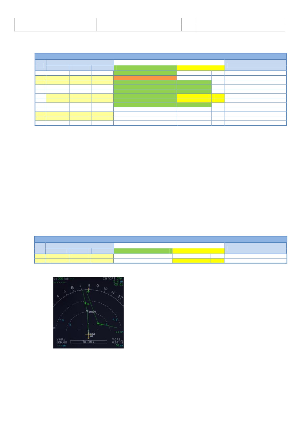
Aerosoft
The Airbus A318/319/320/321 in FSX
Vol
06-01-07 Page 52
Airbus A318/319/320/321
Step-By-Step Tutorial
6
07 April 2015
5.10
Before Takeoff
BEFORE TAKEOFF
PANEL
ACTION
NO.
REMARK
TYP
PART (Name)
PART (No.)
PF (PILOT FLYING)
PM (PILOT MONITORING)
147
INFORMATION TO CABIN CREW
“Please prepare for Takeoff”
148
OVERHEAD
EXT. LIGHTS
9
TAXI TO RUNWAY HOLDING POINT
Start Checklist / Co-Pilot please see below
149
ECAM
WHEEL PAGE
1
BRAKE TEMP = below 150
CHECK
Cop
CoP set Brake Fans On if Brake Temp >150
150
MAIN PANEL
BRAKE FAN
11
BRAKE FANS
OFF
Cop
151
PEDESTAL
ENGINE
5
ENG MODE SEL = NORMAL
CHECK
152
PEDESTAL
TCAS
10
TCAS TA/RA plus TILT ABOVE
SET
CoP
153
OVERHEAD
EXT. LIGHTS
9
EXT. LIGHTS
SET
CoP
Strobes, Land. and Nose Lights
154
PF SLIDING TABLE
STOWED
Cop
Checklist complete
155
PEDESTAL
WXR
11
TILT: UP and select 4 degrees up
SET
156
MAIN PANEL
N/SKID NW
10
A/SKID & NW STRG
CHECK = ON
157
PEDESTAL
RADIO
1
TAKEOFF / LINE UP CLEAR
OBTAIN
If ATC is used
158
PEDESTAL
RADIO
1
ATC (if no AUTO position)
ON
If ATC is used
148. Start Before Takeoff CL: After the TAXI CL has been finished a message on the INFOBAR will pop up
displaying the options to manually start the checklist.
You can start the CL manually using the MCDU 2 CHECKLIST menu option
Just use “1” on the keyboard
For several reasons the automatic start of this checklist has been removed completely.
149. Brake Temperature: BRAKE TOO HOT: Values changed to 150/100°. Before Takeoff CL also accepts
brake temperature of >150° and proceeds if brake fans are ON.
152. TCAS: Use the ring of the knob to set the mode to TA/RA. But below 1000 ft the ND will display TA
ONLY.
153. Ext. Lights: STROBE=ON - BEACON=ON - WING=OFF - NAV&LOGO=2 - RWY TURN OFF=ON - LAND=
ON - NOSE = TO. If light is OFF the copilot sets the switch to ON.
157. Approach Path Clear: Look left and right and assure that the runway is clear. Then enter the runway
08 for takeoff.
5.11
Takeoff (Part 1)
TAKEOFF - Part 1
PANEL
ACTION
NO
REMARK
TYP
PART (Name)
PART (No.)
PF (PILOT FLYING)
PM (PILOT MONITORING)
158
PEDESTAL
THR LEVER
4
SET LEVERS TO
MAN TOGA
159
GLARESHIELD
CHRONO
7
CHRONO
START
CoP
Push upper right button
158. Takeoff:
Picture 54: ND - On the runway - ready for TAKEOFF
At this time the IRS are now automatically aligned with the GPS position and the aircraft should be
displayed on the ND at the beginning of runway 08 (please see picture above).
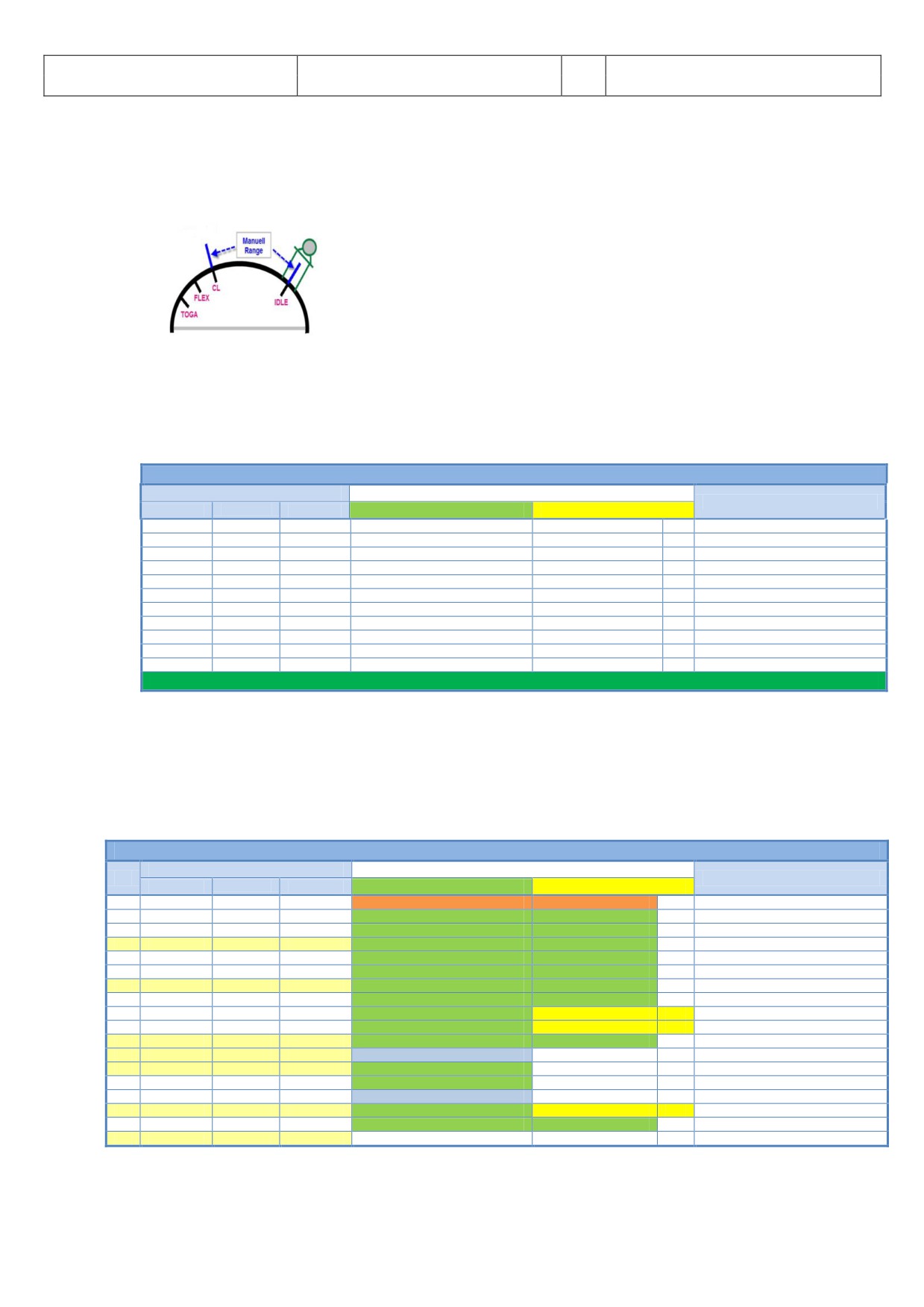
Aerosoft
The Airbus A318/319/320/321 in FSX
Vol
06-01-07 Page 53
Airbus A318/319/320/321
Step-By-Step Tutorial
6
07 April 2015
If cleared for takeoff push the thrust levers to 60 - 70 % N1 (EWD) and monitor the EWD to make sure
thrust is available. If everything is OK, you can push the thrust levers to the TOGA detent (you will
hear three clicks) and it will be confirmed on the FMA. You can also use the FLEX detent (if the runway
is not short or not wet). But for this flight based on the short runway at LOWI we decide to use MAN
TOGA thrust takeoff.
Picture 55: Thrust Lever Positions
159. Start Chronometer: If takeoff thrust has been set (>50% N1) the copilot automatically starts the
chronometer (time is displayed in the lower left corner of the ND).
5.12
Takeoff Abort
ABORT TAKEOFF
PANEL
ACTION
REMARK
TYP
PART (Name)
PART (No.)
PF (PILOT FLYING)
PM (PILOT MONITORING)
PEDESTAL
THR LEVER
6
THRUST LEVERS
IDLE
FSX: F1
PEDESTAL
THR LEVER
6
REV
MAX
FSX: F2 (hold some time)
PEDESTAL
THR LEVER
6
REV
OFF
At 70 knots = FSX: 1
MAIN PANEL
BRAKES
6
AUTOBRAKES
OFF
At 35 knots
PEDESTAL
FLAPS
10
FLAPS
UP
>12 knots
PEDESTAL
SPEED-BR.
8
GRD SPOILERS
DISARM
>12 knots
OVERHEAD
EXT. LIGHTS
9
STROBES
OFF
>12 knots
OVERHEAD
EXT. LIGHTS
9
LANDING LIGHTS
OFF
>12 knots
PEDESTAL
TCAS
10
TCAS
STANBY
>12 knots
PEDESTAL
FLAPS
10
FLAPS
TO POSITION
PEDESTAL
SPEED-BR.
8
GRD SPOILERS
ARM
Please follow procedure again from # 132
If it is necessary to abort takeoff please just draw the thrust levers back to IDLE and set the reversers to
MAX (by using F2 from the keyboard).
Currently there is no special CL after “Takeoff bort”. In such cases please load the T XI ST TE (chapter
4.3 of this manual) and start from there.
5.13
Takeoff (Part 2)
TAKEOFF - Part 2
PANEL
ACTION
NO.
REMARK
TYP
PART (Name)
PART (No.)
PF (PILOT FLYING)
PM (PILOT MONITORING)
160
Takeoff thrust is set
Start Checklist / Co-Pilot - if selected
161
“Takeoff”
162
“M N” „TOG “ and „SRS“
„Power set”
163
“100 Knots”
At 100
164
“Checked”
165
“V1”
At GS = V1
166
“Rotate”
At GS = VR
167
“Positive climb”
Radio Alt >50 ft, VS > 100 ft/min
168
MAIN PANEL
GEAR
7
“Gear up”
GEAR UP
CoP
FSX: G
169
PEDESTAL
SPEED-BR.
6
GROUND SPOILERS
DISARM
CoP
FSX: /
170
MAIN PANEL
GEAR
7
GEAR STOWED
“Gear is up , lights off”
Radio Alt >50 ft, VS > 100 ft/min
171
At Thrust Red. / Acceleration Alt.
172
PEDESTAL
THR LEVER
4
SET LEVERS TO
"CLIMB THRUST"
Blinking announcement in FMA
173
FCU
AP
5
AUTOPILOT
"AUTOPILOT ON"
174
t “Green Dot Speed” / “S-Speed”
175
PEDESTAL
FLAPS
8
“Flaps zero”
SELECT
CoP
FSX: F6
176
“Flaps zero”
Checklist complete
177
FCU
ALTITUDE
3
Cruise Altitude
SET TO 31.000 feet
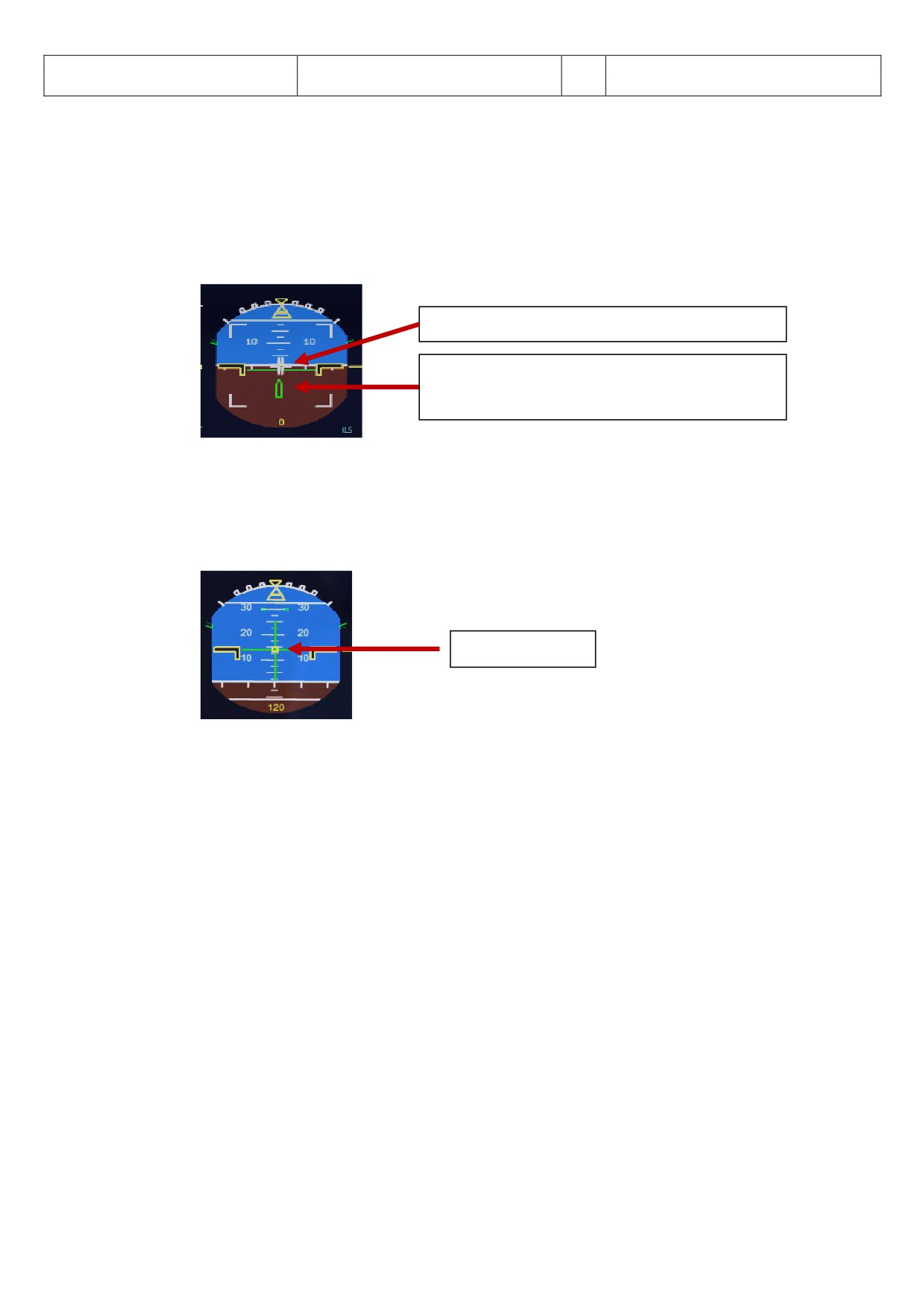
Aerosoft
The Airbus A318/319/320/321 in FSX
Vol
06-01-07 Page 54
Airbus A318/319/320/321
Step-By-Step Tutorial
6
07 April 2015
163.
100 knots: There is no “100 knots” call if V1 is lower than 105 knots
166.
Rotate:
a. During the takeoff roll, the stick should be pressed half way forward until the speed reaches 80
knots. The stick position can be monitored on the PFD (please see picture 54).
b. As soon as the runway has been entered and if it has an ILS, the yaw bar appears on the PFD to
help guiding the aircraft along the runway centerline (please also see picture 54). But this not the
case at LOWI Rwy 08.
Sidestick-Position
Yaw Bar - Runway Position
(Because of no ILS it is not available at LOWI 08)
Picture 56: Joystick: On the runway (attitude indicator)
c. When the speed is over 80 knots, the stick can be released to come back to a neutral position.
d. When VR = 120 knots is reached (indicated by a magenta circle on the PFD speed tape), the
Copilot will announce “ROT TE” - then pull the stick for the rotation. If the FD (showing max. 18°
pitch angle) is not perfectly stable at this time, take a 15° pitch angle.
Flight Director
Picture 57: Flight Director: During takeoff
e. Shortly after takeoff the joystick position indicator and the runway yaw bar on the Attitude
Indicator will disappear and Flight Director Indicator will show up (please see picture above).
xxx. A.FLOOR: If you are flying with a too high pitch automatically the Alpha Floor mode (Display =
A.FLOOR in PFD / FMA section) will be switched on i.e. full thrust automatically will be set - not
considering the position of the thrust levers. As soon as the pitch is back to normal the thrust levers
will be automatically set back to TOG LK (displayed on the FM
). This is a “locked” = fixed mode and
can only be switched off using the following procedure:
a. Set the thrust levers into the TOGA position
b. Switch off auto thrust using the FCU button
c. Now bring back the thrust lever to the CL position
d. Activate auto thrust again using the FCU button
e. If already activated the Autopilot has to be switched to ON again
170. Landing Gear - Autobrake: The autobrake will automatically turn off 10 seconds after the Landing
Gear is retracted
171.
Thrust Reduction Altitude: When the THR RED altitude is reached (3407 feet in our example - airport
172.
elevation plus 1500 feet) a flashing LVR CLB message appears on the FMA (1st column). Move the
thrust levers back to the CL detent (two clicks back). As the thrust reduces when the levers are moved
back to the CL detent, you should anticipate the pitch reduction caused by this thrust reduction. Take
a 10° pitch angle.
XXX. Acceleration Altitude (normally = Thrust Reduction Altitude): At this altitude the CLB modus becomes
active on the FMA (2nd column). The aircraft will now accelerate to the target speed of 250 knots
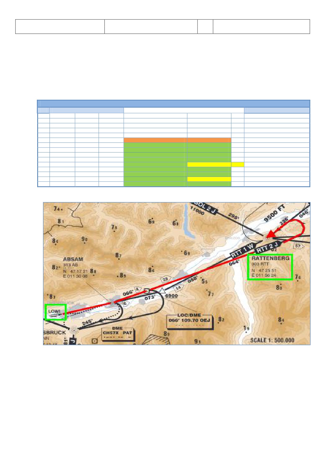
Aerosoft
The Airbus A318/319/320/321 in FSX
Vol
06-01-07 Page 55
Airbus A318/319/320/321
Step-By-Step Tutorial
6
07 April 2015
(below 10.000 feet) if there are no speed restrictions.
175. FLAPS UP: If Flaps 2 are used for takeoff then at F-speed flaps will be set to “1”.
177. CLIMB / Altitude: Before the first set altitude of 12.000 feet will be reached (see # 69) please enter
the chosen cruise altitude from the MCDU = 31.000 feet into the FCU. If they plane already leveled off
at 12.000 feet (no point after 12.000 on the ALT display) then press the ALT button again i.e. managed
mode is selected.
5.14 After Takeoff
TAKEOFF - Part 2
NO.
PANEL
ACTION
REMARK
178
PEDESTAL
WXR
11
TILT: DOWN
SET
179
EFIS
INFOR.
4
EFIS OPTION
ARPT
180
PEDESTAL
RADIO
1
RADIO NAV
CHECK
181
PEDESTAL
ECAM
1
ECAM MENU
REVIEW
182
MCDU
PROG
OPT / MAX ALTITUDE
CHECK
183
FLAPS UP and RETRACTED
Start Checklist / Co-Pilot - if selected
184
PEDESTAL
ENGINE
5
ENG MODE SEL = NORMAL
CHECK
Cop
185
PEDESTAL
SPEED-BR.
6
GROUND SPOILERS
DISARMED
CoP
FSX: /
186
PEDESTAL
FLAPS
8
FLAPS UP and RETRACTED
CHECK
CoP
FSX: F6
187
ECAM
GEAR
2
GEAR IS UP and STOWED
„Gear is up, Lights off“
CoP
188
OVERHEAD
EXT. LIGHTS
9
RUNWAY / NOSE = OFF
OFF
CoP
189
OVERHEAD
AIR COND
7
1 st and 2ND PACK are ON
CHECK
Cop
190
OVERHEAD
ANTI-ICE
8
ANTI ICE (1 &2)
AS REQUIRED
=OFF
191
PEDESTAL
TCAS
10
TCAS = TA/RA and TILT = ABV or N
CHECK and set to ABV
192
EFIS
A PRESSURE
2
BARO REF
X-CHECK (Read out)
Checklist complete
We are flying the SID according to the following chart:
Picture 58: LOWI - Runway 08 - SID RTT2J
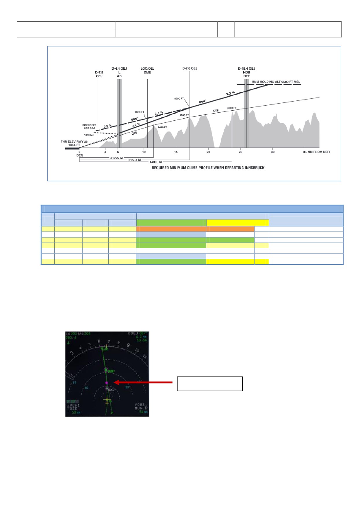
Aerosoft
The Airbus A318/319/320/321 in FSX
Vol
06-01-07 Page 56
Airbus A318/319/320/321
Step-By-Step Tutorial
6
07 April 2015
Picture 59: LOWI - Runway 08 - Climb Profile
5.15 Climb
CLIMB
PANEL
ACTION
NO.
REMARK
TYP
PART (Name)
PART (No.)
PF (PILOT FLYING)
PM (PILOT MONITORING)
193
CLIMB CHECKLIST
Start Checklist / Co-Pilot - if selected
194
At 10.000 feet
195
“Passing 10.000”
196
OVERHEAD
EXT. LIGHTS
9
LANDING LIGHTS
LIGHTS OFF
CoP
197
FCU
ALTITUDE
3
Cruise Altitude
CHECK
=31.000 feet
198
At Transition Altitude
= Checklist completed
199
GL.SH /EFIS
A PRESSURE
13 / 2
BARO REF to STD
SET / X CHECK
CoP
193. Start Climb Checklist: The checklist starts under the following conditions:
"After TO" CL is no longer active
Thrust levers are in Climb mode
FMA State = CLB
195. At 10.000 feet: As soon as the altitude of 10.000 feet is reached it means that the speed restriction of
250 knots is no longer valid. Therefore the aircraft speeds up to the calculated value of 296 knots
(FMGC or MCDU) based on the COST INDEX used for this flight.
10.000 Feet
Picture 60: 10.000 Feet
196. Landing Lights: For high altitude airports (> 5.000 feet) the function has been changed as follows:
During the CLIMB CL the 10.000 feet call is omitted and the landing lights are switched off by
the copilot after the Baro Check at the transition level.
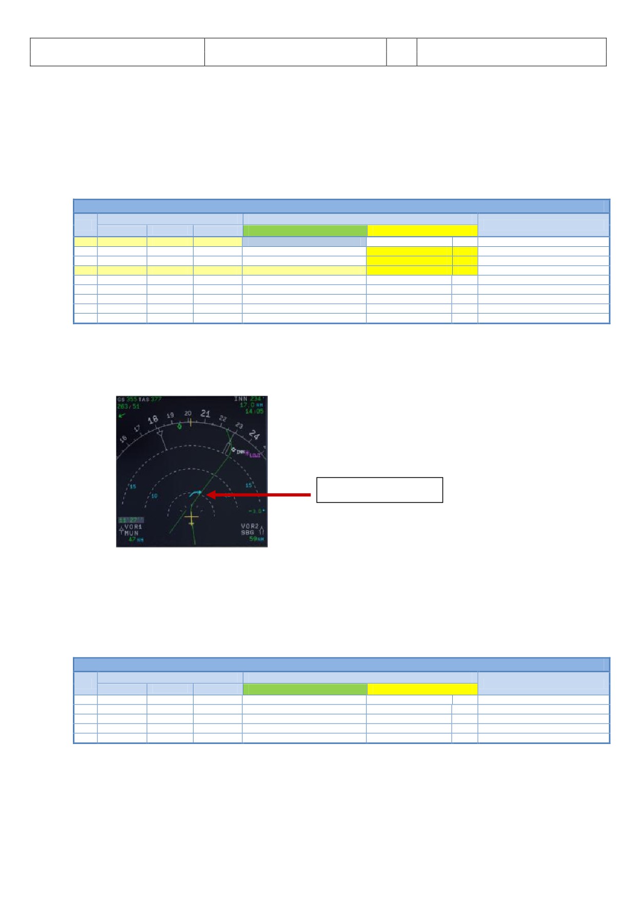
Aerosoft
The Airbus A318/319/320/321 in FSX
Vol
06-01-07 Page 57
Airbus A318/319/320/321
Step-By-Step Tutorial
6
07 April 2015
During the DESCENT also already at the transition level (> 10.000 feet) the Landing Lights as
well as Landing System are set to ON by the copilot.
199. Transition Altitude: Setting up the MCDU we changed the proposed transition altitude (set to 11.000
feet for Innsbruck) i.e. now reaching this value of 11.000 feet the system has to be set to “STD =
Standard”. When the value starts blinking in the PFD please pull the “B RO” button. Please also check
the ISIS (Glareshield #13) e. g. the value is set to STD (right click on the knob at the bottom right)
5.16 Cruise
CRUISE
PANEL
ACTION
NO.
REMARK
TYP
PART (Name)
PART (No.)
PF (PILOT FLYING)
PM (PILOT MONITORING)
200
FMA “ LT / LT CRZ”
Start Checklist / Co-Pilot - if selected
201
PEDESTAL
TCAS
10
TCAS TA or TA/RA plus TILT NORMAL
SET
CoP
202
OVERHEAD
SIGNS
11
SEAT BELTS = OFF or AUTO
CHECK and set to OFF
CoP
203
SLIDING TABLE - COPILOT
EXTENDED
CoP
Procedure complete
204
PEDESTAL
ECAM
1
ECAM MEMO / SYS PAGES
REVIEW
205
MCDU
Var.PAGES
FLIGHT PROGRESS
CHECK
206
MCDU
FUEL PRED
FUEL
MONITOR
207
MCDU
PROG
NAV ACCURANCY
CHECK
208
OVERHEAD
AIR COND
7
CABIN TEMP
MONITOR
200. Cruise Altitude: As soon as the cruise altitude of 31.000 feet has been reached (before passing the
waypoint INN and marked on the ND with a blue arrow showing up) the FMA data on the PFD should
change to MACH, ALT CRZ and NAV. The CRUISE procedure (#201 to #203) will automatically start if
the MCDU is fully programmed. But there are no “calls” for this procedure.
T/C = 31.000 Feet
Picture 61: T/C - Top of Climb = 31.000 Feet
203. Sliding Table: The Copilot’s sliding table will automatically be extended after reaching the cruise level.
5.17
MCDU PERF APPR PAGE
Before starting the Descent Preparation CL and before initiating Descent the MCDU PERF APPR page should be
checked respectively missing data added.
MCDU PERF APPR PAGE
PANEL
ACTION
NO.
REMARK
TYP
PART (Name)
PART (No.)
PF (PILOT FLYING)
PM (PILOT MONITORING)
209
MCDU
PERF
APPR
QNH, TEMP, MAG WIND
ENTER DATA
210
MCDU
PERF
APPR
TRANS ALT
ENTER DATA
= 5000
211
MCDU
PERF
APPR
BARO / RADIO
ENTER DATA
= BARO 210
212
MCDU
PERF
APPR
VAPP
CHECK
213
MCDU
PERF
APPR
LDG CONF
CHECK
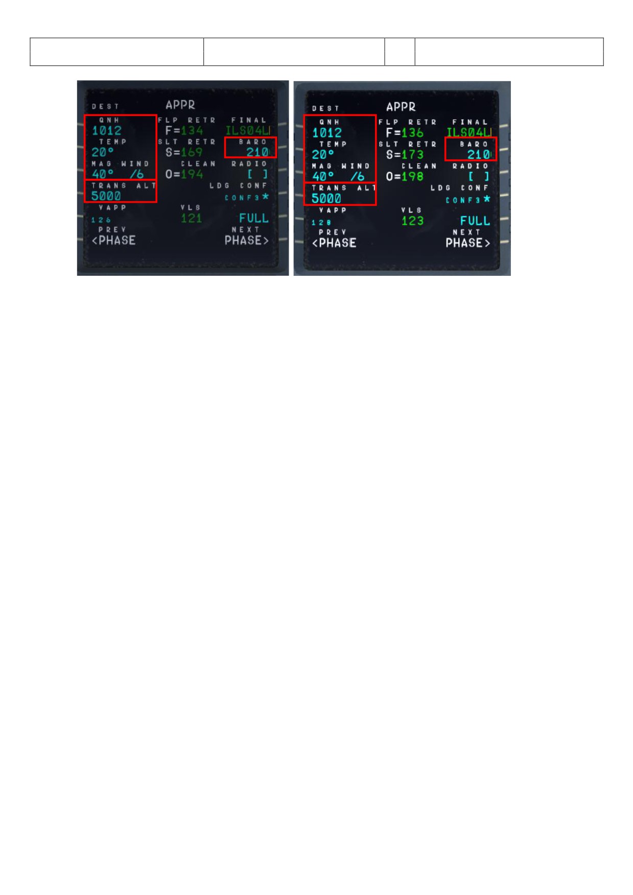
Aerosoft
The Airbus A318/319/320/321 in FSX
Vol
06-01-07 Page 58
Airbus A318/319/320/321
Step-By-Step Tutorial
6
07 April 2015
Picture 62: MCDU - PERF - APPR page (A319 and A320)
209.
QNH; TEMP; MAG WIND: Enter data (for arrival airport LFMN)
210.
TRANSITION LEVEL: (TRANS ALT) for LFMN = 5000 feet (because it is different from transition altitude
of departure airport = 11.000)
211.
BARO - DA (decision altitude): According to the chart for LFMN ILS04L it is a CAT1 ILS approach. Do
not get confused by the CAT 3 FMA on the PFD. This FMA only tells you what the airplane is capable of,
not what the airport is offering. You can only fly a CAT 3 approach if both the FMA says CAT3 and the
airport has a CAT3 ILS.
So as we are flying an ILS CAT1 landing at LFMN we have to enter a Barometric-altimeter DA (decision
altitude). Barometric-altimeter MDA/DA is used for NPA, RNAV as well as ILS CAT1 whereas RADIO-
altimeter DH (decision height) is used for ILS CAT2 and 3 landings. If there is no manual input a
standard BARO value of 200 will automatically be entered by the Copilot. But as the actual BARO-DA
value for our arrival airport LFMN (Nice) Runway 04L and ILS approach is according to the charts = 210
please enter this value.
The information about the available ILS CAT you can get from the charts. The category certification
entails a lot of things. The most important one for CAT2 and CAT3 is a monitoring of the validity of the
ILS signal and a backup power source. For charts there are a few different formats available but on
every ILS chart you will see the capability of the ILS by looking at the minimums. In LIDO charts it is
even spelled out CAT 1, Cat 2 etc. On Jeppesen/AIP charts you sometimes have an extra ILS CAT2/3
charts besides the ILS CAT 1 chart.
212.
VAPP: It is the final approach speed, will automatically be calculated / inserted by the system and
calculated in the following way: VLS plus 1/3 of the tower headwind component. The value of VAPP is
limited so that it is never less than VLS + 5 or more than VLS +15. As a result, VAPP is increased above
its minimum value for runway headwinds above 15 knots. VAPP correction is not increased further for
headwinds exceeding 45 knots.
Additionally the “groundspeed mini function” (GS mini) has been implemented, but it does not change
VAPP, instead, it increases the target (bug) speed when the headwind is greater than the expected
landing headwind - the wind that VAPP was based on. This is done in case the greater headwind
disappeared all at once (wind shear), the airplane would be at VAPP not VAPP minus the loss of wind.
The speed bug moves in response to the wind. For more information on “GS mini” look at
http://www.pprune.org/archive/index.php/t-408276.html.
213.
LDG CONF : (Landing Configuration)If no value is entered manually it defaults to FULL.
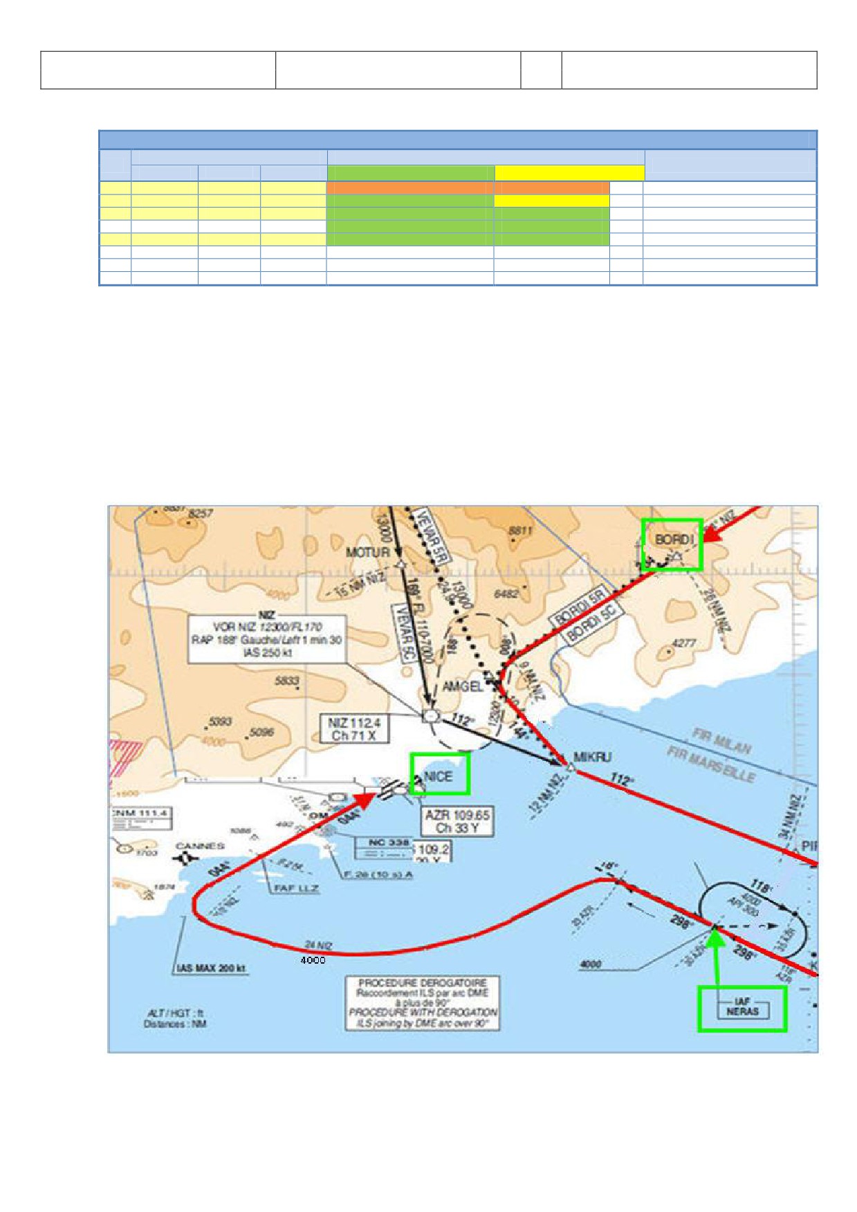
Aerosoft
The Airbus A318/319/320/321 in FSX
Vol
06-01-07 Page 59
Airbus A318/319/320/321
Step-By-Step Tutorial
6
07 April 2015
5.18 Descent Preparation
DESCENT PREPARATION
PANEL
ACTION
NO.
REMARK
TYP
PART (Name)
PART (No.)
PF (PILOT FLYING)
PM (PILOT MONITORING)
214
1 min after CRZ level has been reached
Start Checklist / Co-Pilot - if selected
215
SEAT BELTS = ON or AUTO
CHECK and set to ON
Cop
216
OVERHEAD
ANTI-ICE
8
ANTI ICE = OFF
CHECK
217
PEDESTAL
RADIO
1
LANDING INFORMATION
RECEIVED
If ATC is used
218
EFIS
A.PRESSURE
2
BARO REF = STANDARD
CHECK
Cop
219
MCDU
PERF.
APPR
AIR PRESSURE ARRIVAL AIRPORT
“Checked” and readout
Cop
QNH= 1013
220
MCDU
PERF.
APPR
DECISION ALTITUDE
“Checked”
Cop
BARO = 210
221
MCDU
PERF.
APPR
LDG CONF (Flaps)
"Checked"
CoP
Checklist complete
214. DESCENT PREP. CL: It now can be manually started 1 min after reaching CRZ LVL. 40 NM before T/D
(CRUISE CL still active) - a specific information on the INFOBAR pops up also showing the distance to
the automatic start at 10 NM before the T/D. After the checklist has been finished a message on the
infobar pops up “INITI TE DESCENT”. Initiate descent when the T/D marker on the ND has been
reached.
215. SEAT BELT SIGN : It is also OK if the switch is set to AUTO
216. ANTI ICE: Should be OFF but if ANTI ICE is ON it is also accepted - condition then will be confirmed
218. BARO REF: s we are flying higher than the “transition altitude” it should already be set to “Standard”
i.e. nothing has to be done.
Picture 63: LFMN ILS04L - Chart ST R „BORDI“ / TR NS “NER S”
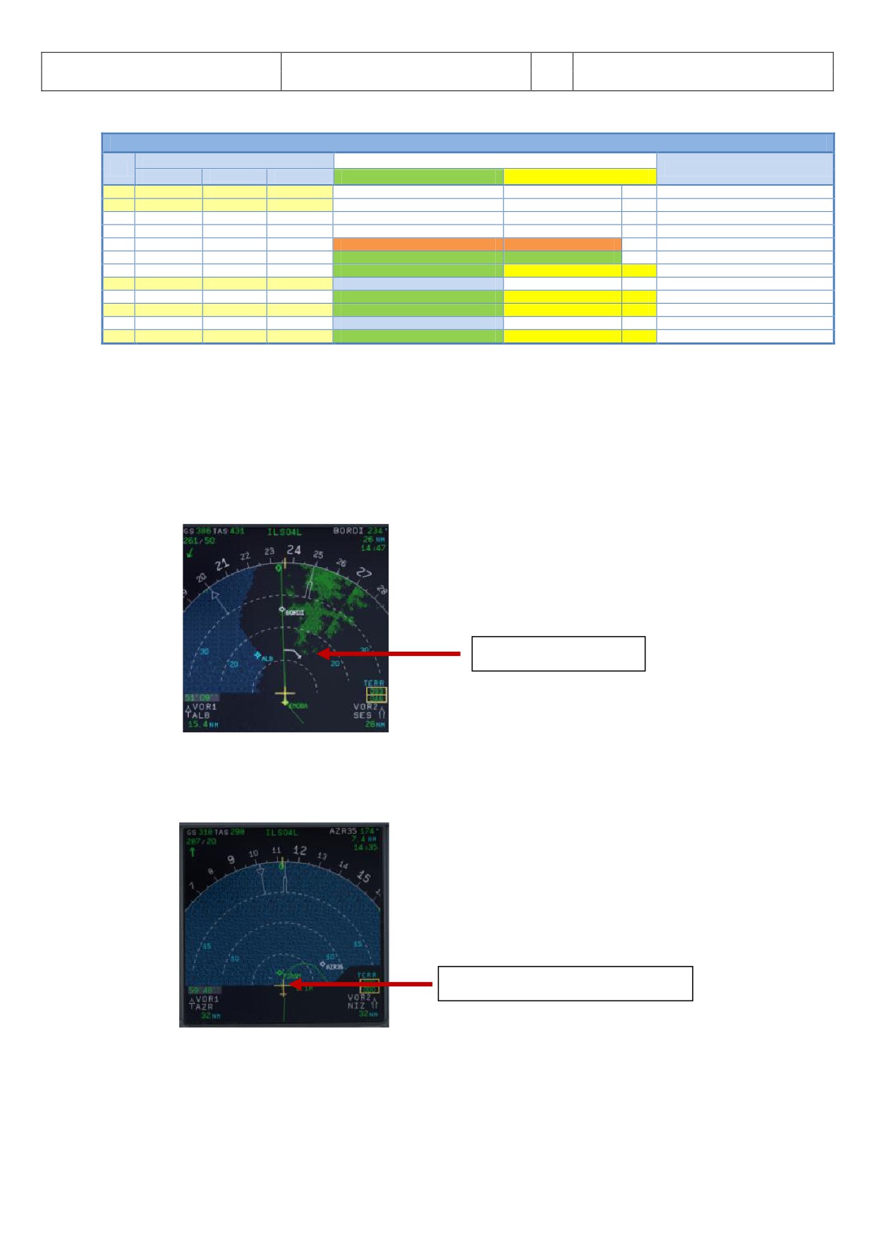
Aerosoft
The Airbus A318/319/320/321 in FSX
Vol
06-01-07 Page 60
Airbus A318/319/320/321
Step-By-Step Tutorial
6
07 April 2015
5.19 Descent
DESCENT
PANEL
ACTION
NO.
REMARK
TYP
PART (Name)
PART (No.)
PF (PILOT FLYING)
PM (PILOT MONITORING)
222
FCU
ALT
3
INSERT NEW HEIGHT
INSERT
= 4.000
223
FCU
ALT
3
INITIATE DESCENT
PUSH KNOB
224
MAIN PANEL
PFD
1
DESCENT
MONITOR
225
PEDESTAL
SP BRAKES
6
SET
AS REQUIRED
226
Vert. Mode = DES / Desc.Prep.CL = compl.
Starts next Checklist / Co-Pilot - if selected
227
MAIN PANEL
PFD
1
FMA
CHECK
228
PEDESTAL
TCAS
10
TCAS = TILT BELOW
CHECK and SET
CoP
229
At 10.000 feet:
230
OVERHEAD
EXT. LIGHTS
9
LANDING LIGHTS
ON
CoP
231
EFIS
FD / ILS
3
ILS LOCALIZER (LS)
PUSH
CoP
EFIS
232
At Transition Altitude
= 5000
233
EFIS
A PRESSURE
2
BARO REF to actual pressure value
SET / X CHECK
CoP
Checklist complete
222. Descent to Altitude: Before the T/D (Top of Descent) point (near BORDI) is reached (marked on the
ND flight path by a white arrow showing down), the altitude should be set to 4.000 feet. But do not
push the knob before T/D is not reached
223. Initiating Descent: There are various methods for descent but we will use:
Managed Mode:. Reaching T/D or if the T/D marker disappears or DECELERATE is displayed on the
PFD (whatever happens first): Just push the knob. The aircraft will now start to descend automatically
according to the flight path calculated in the MCDU - F-PLN.
T/D = 31.000 Feet
Picture 64: Top of Descent - Initiate descent
229. At 10.000 feet: As soon as the altitude of 10.000 feet is reached the speed restriction of 250 knots
becomes valid. Therefore the aircraft automatically reduces the target speed to 250 knots already at
11.000 feet app. before PIRAM.
10.000 feet Deceleration Point
Picture 65: ND: Deceleration Point
231. LS Pushbutton: If the button is used (normally when passing 10.000 feet) the “Vertical Glideslope” as
well as the “Lateral Localizer” shows up on the PFD. The ND display shows ILS04L on top as soon as
the remaining distance to destination is 250 NM or less.
Aerosoft
The Airbus A318/319/320/321 in FSX
Vol
06-01-07 Page 61
Airbus A318/319/320/321
Step-By-Step Tutorial
6
07 April 2015
232. Transition Altitude: Setting up the MCDU PERF APPR page we set it to 5.000 feet for the approach
(#210). So at this altitude the Barometric Reference Value will be set (as well as on ISIS) .
233. Baro Ref Cross Check: The QNH value entered in the MCDU PERF APPR page is used by the copilot. If
no value has been entered there then the current ambient pressure value will be used (= keyboard
[B]). It is not mandatory to fill the QNH-field in the MCDU - PERF - APPR page. But if a value is
entered the unit used (inHg or hPa) must be identical with the settings the FCU - QNH display. If the
unit is later changed the value in MCDU PERF APPR page automatically will be adjusted. The FSX
standard conversion ratio of 1.013 = 29.92 is used for this baro function.
Like in reality the copilot enters those figures in visible steps and not at once. Then there is a pause of
2 seconds - during which the user can enter a different value - before the checklists continues.
5.20
Approach
APPROACH
PANEL
ACTION
NO.
REMARK
TYP
PART (Name)
PART (No.)
PF (PILOT FLYING)
PM (PILOT MONITORING)
234
5 NM before DECEL pseudo waypoint
Starts next Checklist / Co-Pilot - if selected
235
ECAM
ECAM
1
ECAM MESSAGE
CHECK
236
SLIDING TABLE S - STOWED
STOWED
CoP
237
OVERHEAD
SIGNS
11
CABIN SIGNS = ON
CHECK or set to ON
238
MCDU
PROG
NAV ACCURANCY
CHECK
239
EFIS
A.PRESSURE
2
BARO REF CROSS CHECK
SET and Read out
CoP
Checklist complete
240
Initial approach:
241
OVERHEAD
SIGNS
11
SEAT BELTS
CHECK ON
AUTO is also OK
242
PEDESTAL
ENGINE
5
ENG MODE
CHECK NORM
243
Approx. 15 NM from touchdown:
244
MCDU
PROG
NAV ACCURANCY
MONITOR
245
MAIN PANEL
PFD
1
POSITIONING
MONITOR
234. Approach CL: The APPROACH CL now is available for manually start (MCDU2 CHECKLIST MENU =
marked in orange) app. 10 NM before the DECEL pseudo waypoint and a message pops up on the
INFOBAR showing the distance and explains the start options. It starts automatically app. 5 NM
before DECEL pseudo waypoint.
For the start of the APPROACH CL it is not necessary anymore that the DESCENT CL has been finished.
Even if the BARO CHECK has not yet been completed the APPROACH CL can be started. As a reminder
in such a case “DESCENT CL” blinks on the right MCDU.
235. ECAM Message: There is a very important difference between caution (amber) and warning (red). If
the CLR button is ON it is necessary previously to confirm a “warning” or “caution” message.
236. Sliding Table: If the copilots sliding table had been extended at cruise level. Even if the copilots
function is set to OFF now the captains and copilots sliding tables will automatically be retracted.
237. Cabin Signs: SEAT BELTS=ON or AUTO (if OFF Cop sets to ON), NO SMOKING=ON
239. Baro Ref Cross Check: The QNH value entered in the MCDU PERF APPR page is used by the copilot. If
no value has been entered there then the current ambient pressure value will be used (= keyboard
[B]). It is not mandatory to fill the QNH-field in the MCDU - PERF - APPR page. But if a value is
entered the unit used (inHg or hPa) must be identical with the settings the FCU - QNH display. If the
unit is later changed the value in MCDU PERF APPR page will be automatically adjusted.
Like in reality the copilot enters those figures in visible steps and not at once. Then there is a pause of
2 seconds - during which the user can enter a different value - before the checklists continues. The
FSX standard conversion rate of 1.013 = 29.92) is used for this baro function.
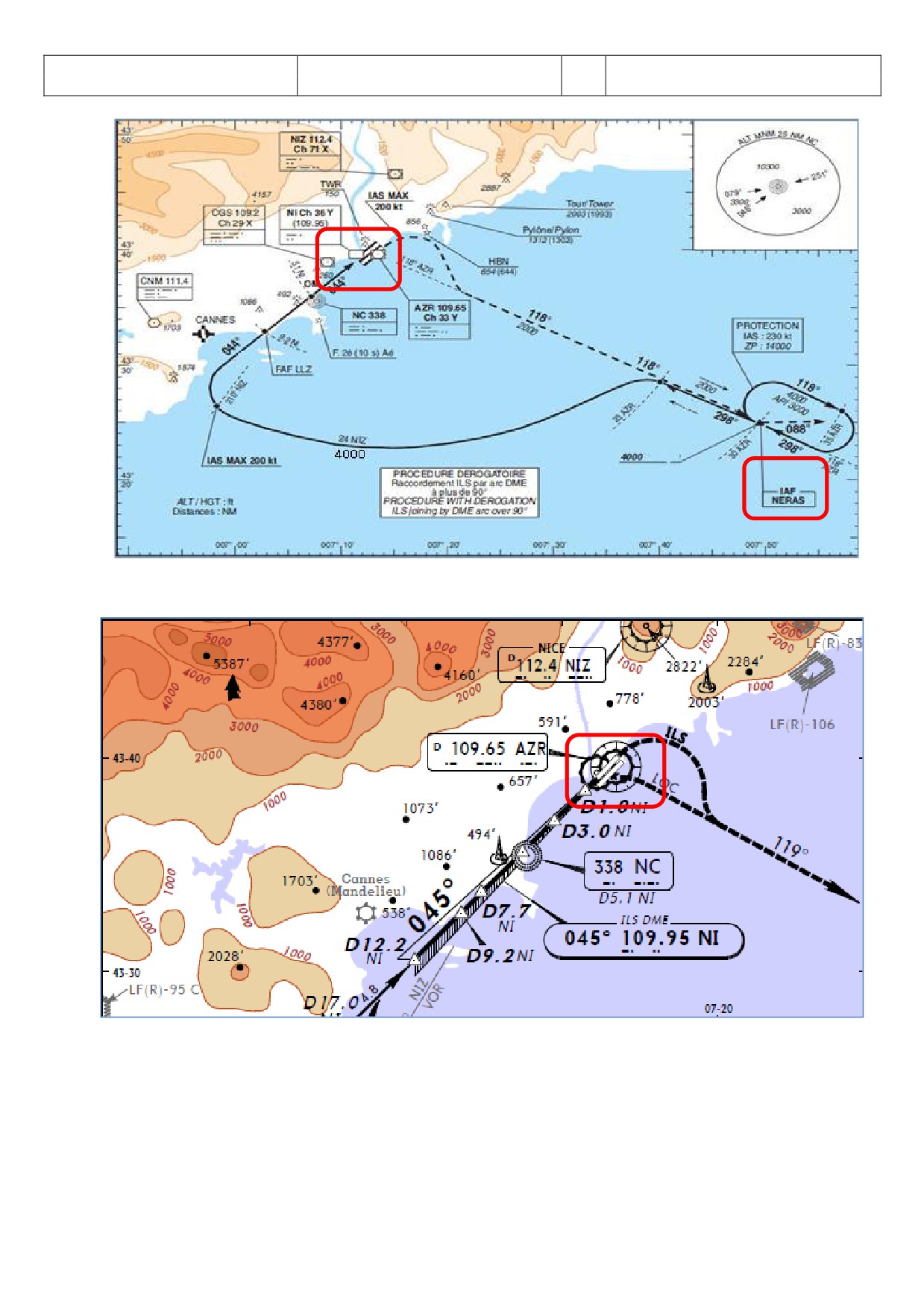
Aerosoft
The Airbus A318/319/320/321 in FSX
Vol
06-01-07 Page 62
Airbus A318/319/320/321
Step-By-Step Tutorial
6
07 April 2015
Picture 66: Chart TRANS NERAS
Picture 67: Chart ILS 04L Nice
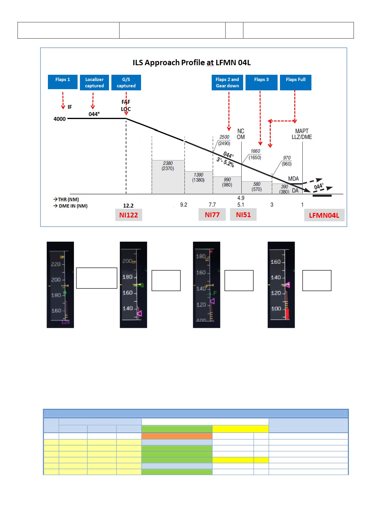
Aerosoft
The Airbus A318/319/320/321 in FSX
Vol
06-01-07 Page 63
Airbus A318/319/320/321
Step-By-Step Tutorial
6
07 April 2015
Picture 68: Final Procedure - ILS Approach Profile LFMN04L
Green Dot
S -
F -
Vapp -
Speed
Speed
Speed
Speed
Picture 69: Speeds “Green Dot”, S, F and Vapp on PFD
5.21 Final
There are two main modes for the approach: Using “Managed Speed” or “Selected Speed (manually)”. Our
Checklist- and Copilot-Function uses the “Managed Speed” mode. This means that the speed is automatically
set by the MCDU and the flaps are manually deployed by the Copilot (based on the situation).
The Final CL activation is “independent” from the activation of the MCDU - PERF - APPR mode activation. The
FINAL checklist will be automatically started after the APPR CL has been completed.
FINAL
PANEL
ACTION
NO.
REMARK
TYP
PART (Name)
PART (No.)
PF (PILOT FLYING)
PM (PILOT MONITORING)
246
Appr. CL has been completed
Starts next Checklist / Co-Pilot - if selected
247
MCDU
PERF
APPR PHASE
ACTIVATE
CoP
248
MAIN PANEL
PFD
1
CALL: LOCALIZER ALIVE
CoP
2499
FCU
APPR
6
APPR
PUSH
250
MAIN PANEL
PFD
1
LOCALIZER CAPTURED
CHECK
241
MAIN PANEL
251
Green Dot Speed
252
PEDESTAL
FLAPS
8
FLAPS 1
SELECT
CoP
FSX: F7
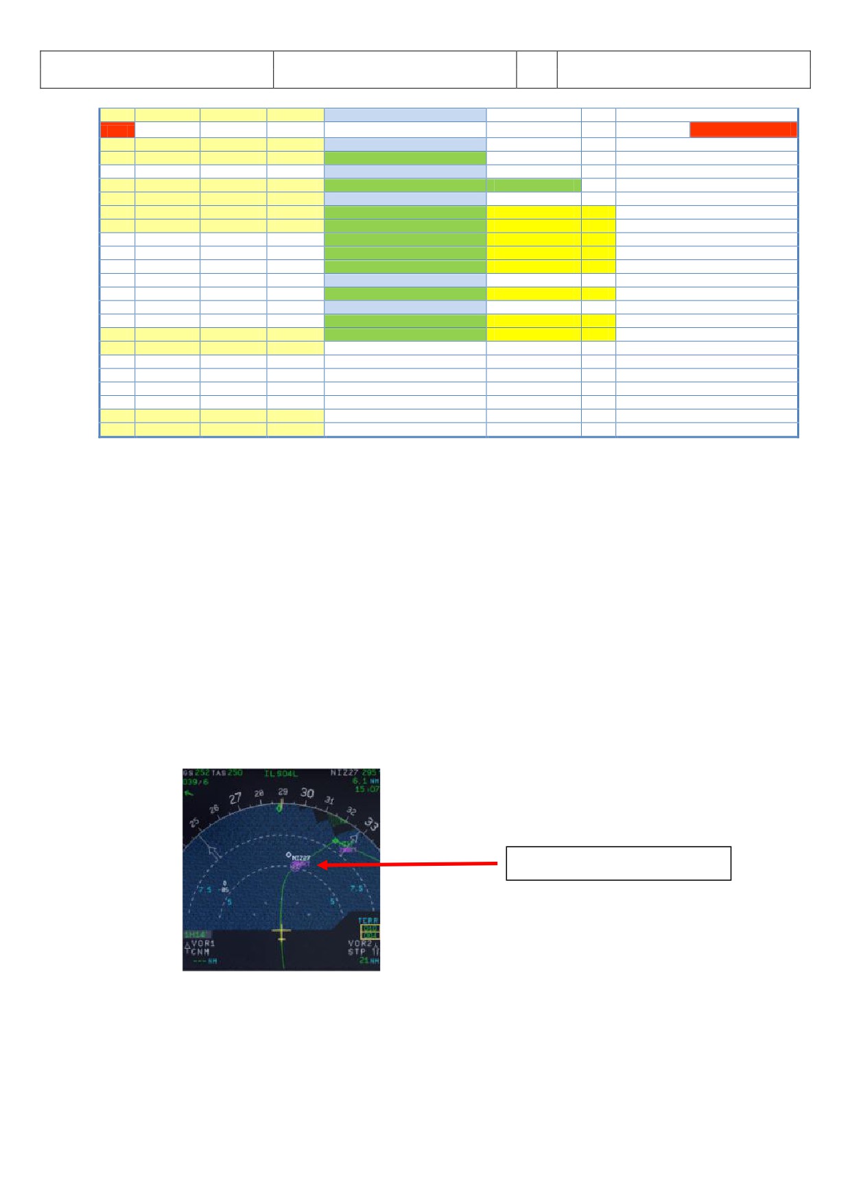
Aerosoft
The Airbus A318/319/320/321 in FSX
Vol
06-01-07 Page 64
Airbus A318/319/320/321
Step-By-Step Tutorial
6
07 April 2015
253
S-Speed
254
PEDESTAL
FLAPS
8
FLAP 2
SET
FSX: F7
OPTIONAL
255
Gkidescope becomes alive
256
FCU
AP
5
Second AP
ON
257
Glidescope captured
258
MAIN PANEL
PFD
1
G/S CAPTURE
CHECK
259
Rad. Alt. > 2.000 ft = LANDING MEMO
260
PEDESTAL
FLAPS
8
FLAPS 2
SELECT
CoP
FSX: F7
261
FCU
ALT
4
GO AROUND ALT
SET TO 2.000 FEET
CoP
Just enter - do not push knob
262
MAIN PANEL
GEAR
7
L/G DOWN
SELECT
CoP
FSX: G
263
PEDESTAL
SPEED-BR.
6
GROUND SPOILERS
ARM
CoP
Mouse click: right
264
OVERHEAD
EXT. LIGHTS
9
NOSE LIGHT (if not TAXI) = TO
ON
CoP
265
When L/G down, below REF SPEED
266
PEDESTAL
FLAPS
8
FLAPS 3
SELECT
CoP
FSX: F7
267
Next REF SPEED:
268
PEDESTAL
FLAPS
8
FLAPS FULL
SELECT
CoP
FSX: F7 / Checklist complete
269
MAIN PANEL
EWD
5
LANDING MEMO
CHECK NO BLUE
270
FCU
SPD
1
Set speed to VApp
SET
= 126 (MCDU - PERF - APPR page)
271
PEDESTAL
TCAS
10
TCAS
SET TO „TA ONLY“
272
MAIN PANEL
PFD
1
FMA
CHECK
273
MAIN PANEL
PFD
1
LOC CAPTURE
MONITOR
274
ECAM
ECAM
1
ECAM WHEEL PAGE
CHECK
275
FCU
ATHR
7
A/THR
CHECK SPD
276
OVERHEAD
ANTI-ICE
8
WING ANTI ICE
CHECK OFF
247.
Initiate Approach Phase:
After the APPROACH CL has been finished the APPR PHASE in the MCDU PERF APPR page
immediately should be manually activated (RW procedure).
If the MCDU F-PLAN DECEL pseudo waypoint (calculated by the FMGC to initiate deceleration in
order to be stabilized at VAPP at a specified point on the approach profile, normally at 1000 feet
AGL) is different from the point at which the APPR PHASE automatically will be initiated (7.200 feet
radar altitude), it is ILS or NPA approach and distance to the airport less than 30 NM) a warning will
appear on the INFOB R “MCDU: Manually activate PPR PH SE”.
Manually activated by the user (MCDU - PERF - APPR page) if warning appears on the INFOBAR
“MCDU: Manually activate PPR PH SE”. In the “real world” the PPR PH SE is always activated
manually and never automatically.
Automatically at the Deceleration Pseudo Waypoint
(please see picture below) if the
APPROACH CL has been finished; the flight level is below 7.200 feet radar altitude, the RNAV
mode is active and the distance to the airport is less than 30 NM. The (DECEL) pseudo waypoint
is calculated by the FMGC to initiate deceleration in order to be stabilized at VAPP at a specified
point on the approach profile, normally at 1000 feet AGL.
Deceleration Pseudo Waypoint
Picture 70: Deceleration Point
248.
LOC Alive: Before NI17 the localizer becomes “alive” and this will be confirmed by a PM call
“LOC LIZER LIVE”. The conditions for this call are: The angle to the runway must be smaller
than 90 ° and the Approach, Landing as well as BaroCheck are not active.
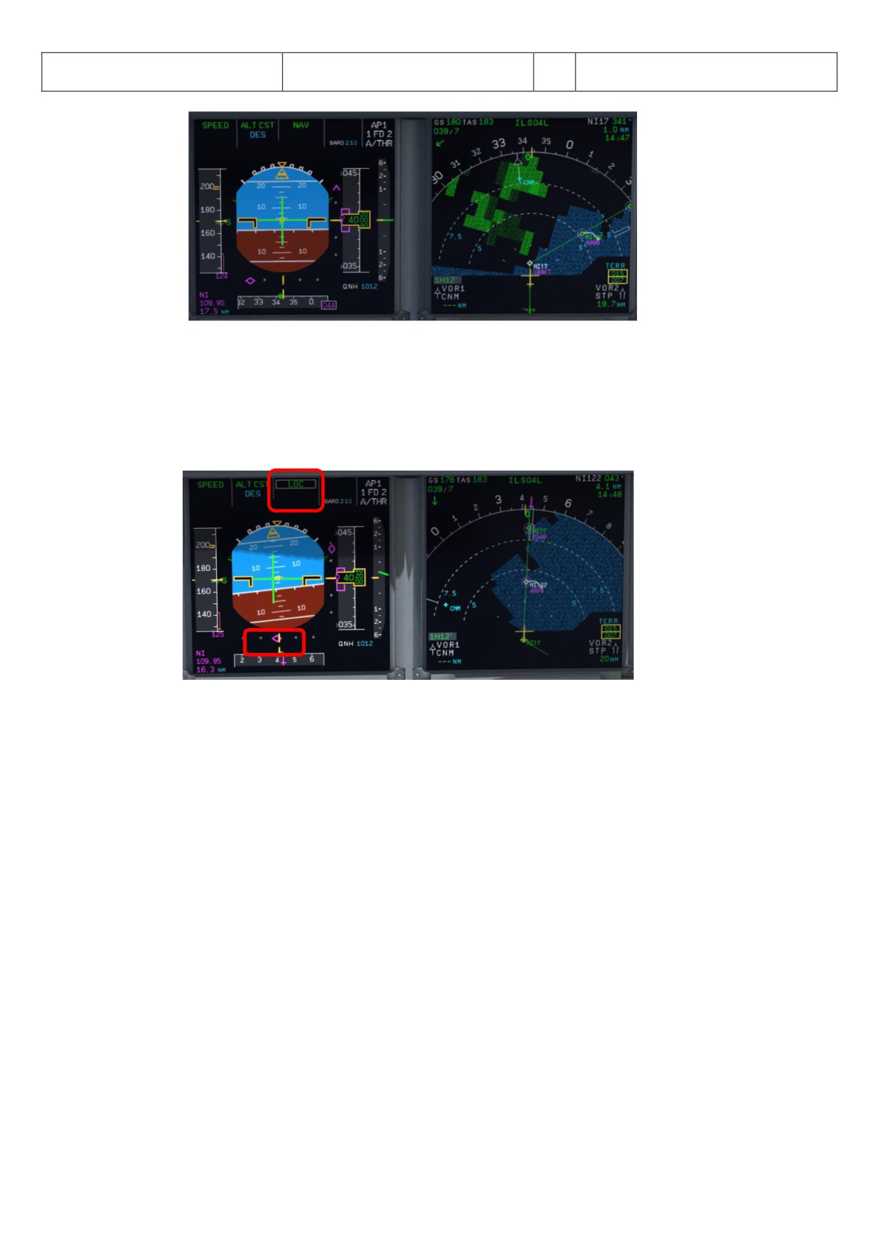
Aerosoft
The Airbus A318/319/320/321 in FSX
Vol
06-01-07 Page 65
Airbus A318/319/320/321
Step-By-Step Tutorial
6
07 April 2015
Picture 71: LOC initiated near NI17
249.
APPR Button: Before passing NI17 (you are already flying at NI122) and after hearing the call
“LOC LIZER LIVE” = press the APPR button on the FCU.
250.
LOC Capture: The “capture” will be confirmed i.e. lateral path has been caught. Please note: If you
are pushing the APPR button too early (before turning to NI17/NI122) it might happen that the
plane captures the localizer in the wrong direction. Please see also chapter 10.4 for details. First the
lateral path will be caught (LOC* or LOC displayed on the PFD -FMA)
Picture 72: LOC captured
251.
Green Dot Speed / CLEAN: After initiating the APPR Phase (#242) automatically the MCDU reduces
the speed to “Green Dot Speed” (195 knots). But if the plane is already on the glidescope it is not
going to change its pitch to reduce to “Green Dot Speed”.
252.
Flaps: During the approach the flaps will be slowly step by step extended from 1 (after reaching
“Green Dot Speed”) to FULL based on aircraft speed - The flaps will be extended to 1 at least
automatically 10 NM before the runway threshold if IAS is below VFE.
253.
S Speed: After the flaps are deployed by the Copilot to 1 the MCDU automatically reduces the speed
to S-Speed (172 knots). If the plane does not slow down to S-Speed then just use the speed brakes
until S-Speed is reached.
Some general information on the use of speed brakes:
Normally you can use them whenever wanted. But there are some SOP things which have to be
considered. The first one has to do with high altitude flying (FL300 and higher). You cannot yank
them to their full position at once. You have to be smooth as to not disrupt the airflow to sudden.
When on auto pilot the speed brake will not even fully open even if you put the lever at full. The
Airbus is limiting the deployment a bit.
The second thing is that you may not use the speed brakes with flaps three or full. This will cause a
roll moment that could impair controllability. Some models even have an autoretract when having
the speed brakes out at Flaps three/full.
The whole point of the speed brakes is to slowdown the aircraft or to make it descent faster. If the
autothrust is on and in SPEED mode it could be that the engine needs more thrust than idle to keep
the managed/selected speed and this will give a warning. Having the speed brakes out and throttling
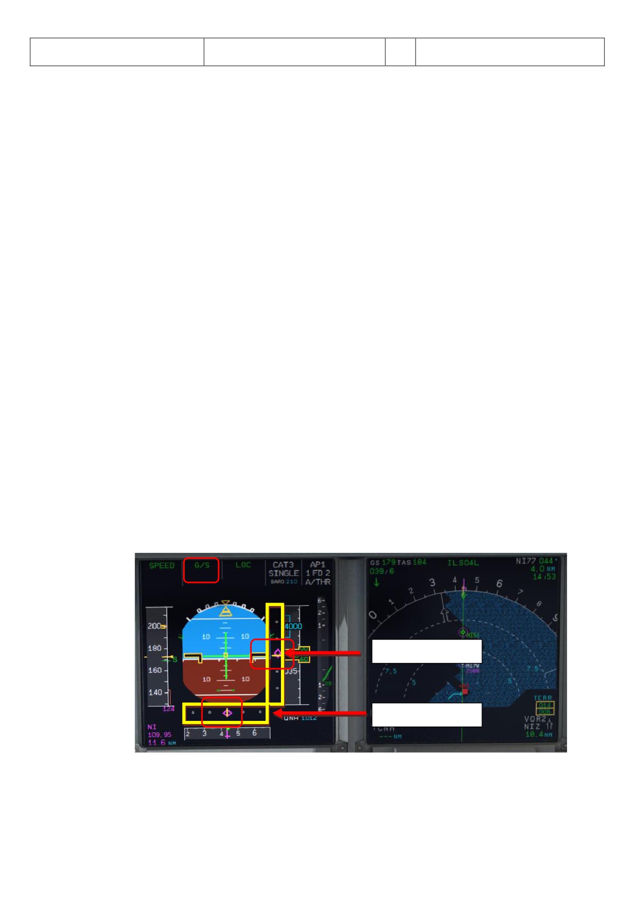
Aerosoft
The Airbus A318/319/320/321 in FSX
Vol
06-01-07 Page 66
Airbus A318/319/320/321
Step-By-Step Tutorial
6
07 April 2015
up is a no-no. It just does not make sense.
254.
FLAPS 2 (OPTIONAL): Another method to reduce to S-Speed is to manually deploy the flaps to 2
already just after setting the flaps to 1 but keep in mind the VFE limits. This method is also
supported by the Checklist- and Copilot-Function.
255.
Glideslope “alive”: When the Localizer has been captured (please see picture #70 above) soon after
the vertical glide slope becomes “alive” (magenta rhombus fully appears) which will be confirmed by
a call.
256.
Autopilot:
-
Only with an ILS approach programmed in the FMGC, the approach phase activated and the
APPR button pushed on the FCU you do have the possibility to select both P’s at the same
time. This will show as AP 1+2 in the PFD FMA.
-
It is normal Airbus procedure to also select the second AP during an ILS approach. It does not
matter if this approach is a CAT 1, 2 or 3. The main reason for this is that if one AP goes offline
the other can take over. This is a principle that is called fail operational. Meaning that when one
AP disconnects for whatever reason the second one will take over immediately - without any
interference/action by the pilot. But in reality only one AP is doing the flying and the other one
is just standing by to take over if needed. To have both P’s active is a requirement for CAT 3
approaches but it gives an added safety with CAT 1 and 2. So why not selected both during all
ILS approaches Airbus must have thought.
-
Autoland goes hand in hand with CAT 2 and 3 approaches but as a system it is separate.
Autoland is technically possible with 1 AP but certification of the airline, airport, and airplane
must all be met.
-
An ILS CAT 1 may be landed manual at all times. A CAT 2 may be landed manual but this is also
up to certification rules for the airline, airport and airplane - but normally an autoland is the
norm here. A CAT 3 must be made with an auto land system.
-
If autoland is used it means that there is no manual flight path interference of the pilots until
after touchdown and the aircraft is landing fully automatic.
-
In our case because LFMN ILS 04L allows only CAT 1 landings we will use both autopilots but will
make no “autoland”.
Additional information on the various CAT you will also find in #211.
258.
Glideslope “captured”: When the glideslope has been captured it will be confirmed by a call. After
the vertical glide path has been caught the display on the PFD-FMA looks as follows (please see
picture 71 below):
Vertical glide path
Lateral path
Picture 73: PFD - Glidescope captured - Vertical and lateral glide path
The middle of both fields shows the vertical and lateral position of the aircraft where as the
magenta rhombus shows the actual position on the glide path. This means that during the approach
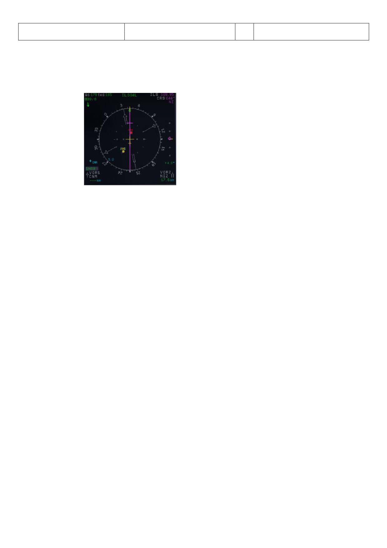
Aerosoft
The Airbus A318/319/320/321 in FSX
Vol
06-01-07 Page 67
Airbus A318/319/320/321
Step-By-Step Tutorial
6
07 April 2015
both rhombuses are moving to the center. The picture above shows a position at which the aircraft
is on the nearly ideal position for landing.
On the EFIS control panel please change the knob for the various views to LS. This view also shows
the glide path and the position of the aircraft to it.
Picture 74: ND - ILS view LFMN Rwy 04L
259.
Landing Memo: The conditions for the Landing Memo are:
< 2000 feet RA above runway altitude
Flight mode: Cruise or Approach
Both thrust levers at or below CL detent
The “L NDING” checklist is “interrupted” until the “Landing Memo” becomes available in the Upper
ECAM. The Copilot then continues with the settings i. e. flaps 2, gear down etc.
259a.
Speed Restriction 160 knots: On certain airports like p. e. EGLL speed restrictions apply like 160 kts
before till 4 NM before the runway. This is a bit difficult because on the other hand SOP states the
plane has to be fully established at 1000 feet RA. So Flaps 2, speed brakes and sometimes even gear
down is used to keep the 160 knots. If the Checklist, the Copilot and SPD SEL = 160 knots is used the
gear will not automatically be deployed at <2000 feet RA as well as the flaps not set to 3 and full -
only after SPD SEL is <160 knots or in MNGD mode.
260.
Flaps 2: At calculated speed (but must be lower than VFE = 200 knots) the flaps are automatically
extended to 2 by the copilot (if = ON). If the calculated flaps 2 extension speed is higher than VFE
the plane must be near MLW or even above. This means it is an emergency situation. In such a case
do not use “Managed Speed”, but set the speed manually to a value below VFE = 200 knots (e.g. 195
knots). The flaps then will be automatically extended by the copilot (if = ON). After the flaps have
been extended to 2 you can again use “Managed Speed” for landing.
261.
GoAround ALT: This is the altitude a plane has to fly to when using the GO AROUND procedure
(MCDU FPLAN waypoints in blue) in case a landing has to be aborted. Set the GoAround Altitude
according to the FPLAN e.g. change the set altitude on the FCU to the first altitude to be reached
after a “Go round”. Please just change the altitude and do not press or pull the knob at this point.
In case the Copilot function is enabled it is automatically set by the copilot under following
conditions:
FAF passed - plus 0.5 NM added
Actual flight level below GA ALT
Actual flight level below FCU set ALT
Vertical speed below 250 knots
If the copilot function is set to ON the highest value is automatically inserted using the MCDU FPLAN
data. The value will be entered by the copilot in visible steps (with sound) and also considering the
100 and 1000 switch. Some values like 3.490 feet cannot be entered so the next possible higher
value which means for 3.490 = 3.500 has to be or are entered.
If no values are available in the F-PLAN or there is no GA flight path available in the NAV DB the
copilot sets the value to a value of (airport altitude rounded to next full 1.000) plus 4.000 feet e. g.
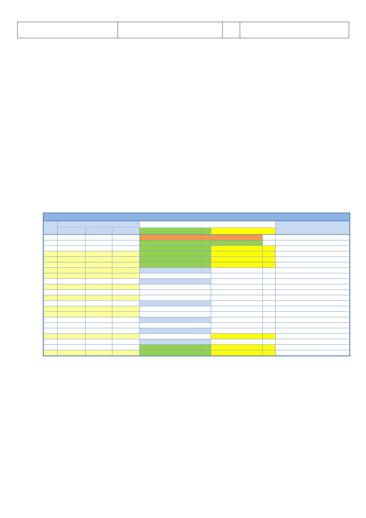
Aerosoft
The Airbus A318/319/320/321 in FSX
Vol
06-01-07 Page 68
Airbus A318/319/320/321
Step-By-Step Tutorial
6
07 April 2015
normally to 5.000 feet.
269.
Landing Memo / blue entries - : Please check if there are no “blue” entries in the Landing Memo. If
for some reasons there are still “blue” entries (you might have forgotten to make certain settings)
then please make those settings now.
270.
Set VAPP: After the flaps are set to FULL and the landing gear is down the speed now should be
changed to Vapp speed in our example to 126 as calculated by the FMGC - MCDU (PERF APP). As we
are flying in “Managed Mode” the speed automatically is reduced to Vapp after the flaps are set to
FULL - i.e. nothing has to be done as we are using the “Managed Mode”.
It is the final approach speed and automatically be calculated / inserted by the system. It is
calculated in the following way: VLS plus 1/3 of the tower headwind component. The value of VAPP
is limited so that it is never less than VLS + 5 or more than VLS +15. As a result, VAPP is increased
above its minimum value for runway headwinds above 15 knots. VAPP correction is not increased
further for headwinds exceeding 45 knots. No additions are made for gusts.
275.
Auto Throttle: Leave the
/THR on͙..
276.
Wing Anti Ice: Leave the Wing Anti Ice OFF
There are also various other approach procedures used depending on airline and weather condition (ILS- and
non-ILS-approaches).
5.22
Landing
LANDING
PANEL
ACTION
NO.
REMARK
TYP
PART (Name)
PART (No.)
PF (PILOT FLYING)
PM (PILOT MONITORING)
277
Flaps in Landing Config. (MCDU Settings)
Start next Checklist / Co-Pilot - if selected
278
MAIN PANEL
GEAR
7
LAND. GEAR = FULL EXTRACTED
CHECK
CoP
279
PEDESTAL
SP. BRAKEs
6
GROUND SPOILERS = ARMED
CHECK
CoP
FSX: Right mouse click
280
MAIN PANEL
AUTO BRAKE
6
AUTO BRAKES = MEDIUM
SET
CoP
281
OVERHEAD
EXT. LIGHTS
9
NOSE = TO or TAXI / LANDING L. = ON
CHECK
CoP
282
FCU
ALT
3
GO AROUND ALT
CHECK
CoP
283
AT DECISION ALTITUDE
284
FCU
AP
5
AP
OFF
CoP
FSX: Z
285
At 20 feet:
286
FLARE
PERFORM
287
MAIN PANEL
PDF
1
ALTITUDE
MONITOR
288
PEDESTAL
THR LEVER
4
THRUST LEVERS
IDLE
FSX: F1
289
At touchdown:
290
PEDESTAL
THR LEVER
4
REV
MAX
FSX: F2
291
BRAKES
AS REQUIRED
292
At 70 knots:
293
PEDESTAL
THR LEVER
4
REV
IDLE
FSX: F1
294
At taxi speed:
295
PEDESTAL
THR LEVER
4
REV
STOW
CoP
296
Before 30 knots:
297
MAIN PANEL
AUTO BRAKE
6
AUTOBRK
DISENGAGE
CoP
Checklist complete
298
FCU
AP
5
AP (if applicable)
OFF
CoP
FSX: Z
280. Auto Brake: Set to MED (medium)
281. Exterior Lights: Just check if all Exterior Lights are on: Strobe, Beacon, Nav & Logo as well as Landing
Lights.
282. Go Around Altitude: Check if the GA has been set correctly according to #262.
283. BARO - DA (decision altitude): Please also see #211 - for LFMN ILS 04L according to the charts = 210
feet. t an altitude of 310 feet there will be a call “100 BOVE”.
284. Autopilot: Because LFMN ILS 04L is ILS C T1 we are not allowed to use “ UTOL ND” and have to
disconnect the autopilot at latest at the decision altitude of 210 feet.
286. LAND and FLARE mode: As the aircraft gets closer to the ground the LAND mode engages, then the
FLARE mode. The actual modes are shown on the FMA.
288. Thrust Levers: IDLE: There is a callout: RETARD. A single callout if thrust levers are retarded in time,
multiple callouts if not (auto landing = callout at 10 ft, manual landing = at 20 ft).Pull the trust levers
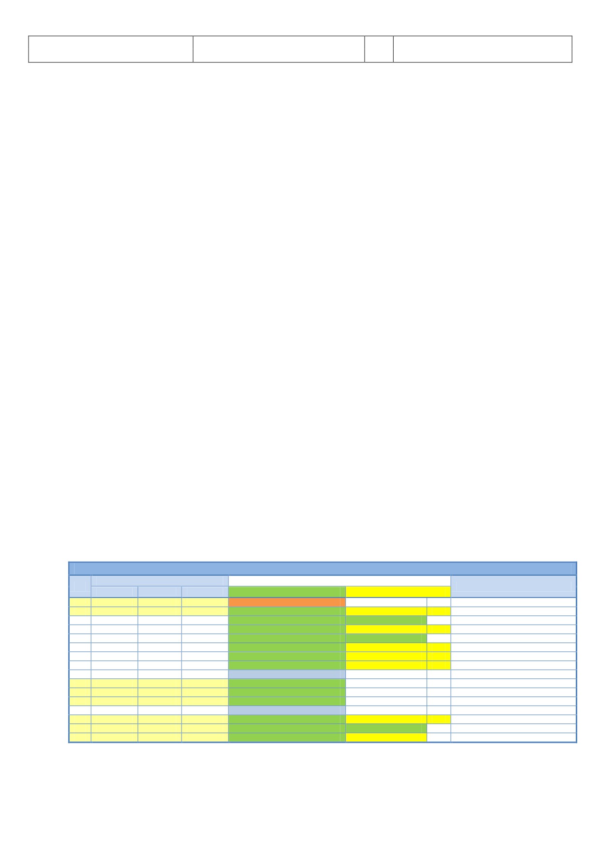
Aerosoft
The Airbus A318/319/320/321 in FSX
Vol
06-01-07 Page 69
Airbus A318/319/320/321
Step-By-Step Tutorial
6
07 April 2015
back to IDLE and let the aircraft gently touch the ground.
290. Trust Levers: REV: After touchdown the thrust reversers (by using F2 from the keyboard) might be
activated but not necessarily if noise abatement procedures prohibits it.
291. BRAKES: The autobrake makes the aircraft decelerate on the ground. You can also take the control at
any time by using the brakes. Any manual action on the brakes automatically disconnects the
autobrake system.
295. REV THRUST: If REV THRUST is used (#284 and #287) the levers are automatically stowed by the
Copilot.
298. AUTOPILOT: We switched the autopilot OFF because at LFMN ILS04L = ILS CAT1 we are not allowed to
make an “ UTOL ND”. But for ILS CAT2 and 3 landing (if the AP is ON) shortly after landing e. g. the
plane is still on the centerline the autopilot is automatically switched off and the warning signal goes
on. The signal will automatically be switched off by the Copilot.
5.23
Go Around
The GO AROUND flight path is displayed on the ND (in blue) if:
A missed approach waypoint (MAP in blue) is displayed on the MCDU F-PLAN page (in line 2, 3, 4 and/or
5), while ND is in ROSE or ARC mode or
Displayed on the MCDU F-PLAN page in line 2, while ND is in PLAN mode.
The GO AROUND procedure is as described below:
After initialization of the G
„GO ROUND CTIVE“ is displayed on the INFOBAR.
After reaching GA ALT and the AFTER TO CHECKLIST has been finished "CLIMB OR CONTINUE FOR NEW
PPRO CH“ is displayed on the INFOBAR.
If additionally to the GA ALT a higher altitude is selected:
o Up to 10.000 ft: Nothing has to be done and there is no INFOBAR display.
o Higher than 10.000 ft: The checklist function changes into CLIMB- and after that as usual into
CRUISE-, and DESCENT PREP-mode (initialization maybe without delay because no T/D is
available). The remaining procedure is according to a normal approach.
Generally the Approach CL will be initialized after a GA 30 NM and automatically started 25 NM before
the destination airport. A message is displayed on the INFOBAR: APPR. CL STARTS IN x MILES OR
MANUALLY ST RT CL ͙͙ E. g. it can be manually started using „1“ from the keyboard or from the
MCDU2 menu itself.
When the APPR. CL has been finished manually start the MCDU PERF APPR. PHASE (also a respective
message appears on the INFOBAR)
GO AROUND
PANEL
ACTION
NO.
REMARK
TYP
PART (Name)
PART (No.)
PF (PILOT FLYING)
PM (PILOT MONITORING)
A
PEDESTAL
THR LEVER
4
GA thrust is set
SET
Start Checklist / Co-Pilot - if selected
B
PEDESTAL
FLAPS
8
“GO AROUND FLAPS”
FLAPS ONE STEP BACK = 3
CoP
FSX: F6
C
“Positive climb”
Radio Alt >50 ft, VS > 100 ft/min
D
MAIN PANEL
GEAR
7
“Gear up”
GEAR UP
CoP
FSX: G
E
MAIN PANEL
GEAR
7
GEAR STOWED
“Gear up , Flaps 3”
F
PEDESTAL
SPEED-BR.
6
GROUND SPOILERS
DISARM
CoP
FSX: /
G
OVERHEAD
EXT. LIGHTS
9
RUNWAY / NOSE = OFF
„Off“
CoP
H
MAIN PANEL
BRAKES
6
AUTOBRAKES
„Off“
CoP
I
At Thrust Red. / Acceleration Alt.
J
PEDESTAL
FLAPS
8
“Flaps 1”
SELECT
CoP
FSX: F6
K
PEDESTAL
THR LEVER
4
SET LEVERS TO
"CLIMB THRUST"
Blinking announcement in FMA
L
FCU
AP
5
AUTIOPILOT
ON
M
t “Green Dot Speed” / “S-Speed”
N
PEDESTAL
FLAPS
8
“Flaps up”
SELECT
CoP
FSX: F6
O
“Flaps up”
Checklist complete
P
FCU
AP
5
AUTOPILOT 2
„Off“
CoP
A.
Thrust Levers: TOGA: If there is an emergency situation and “Go-around” should be performed e.g.
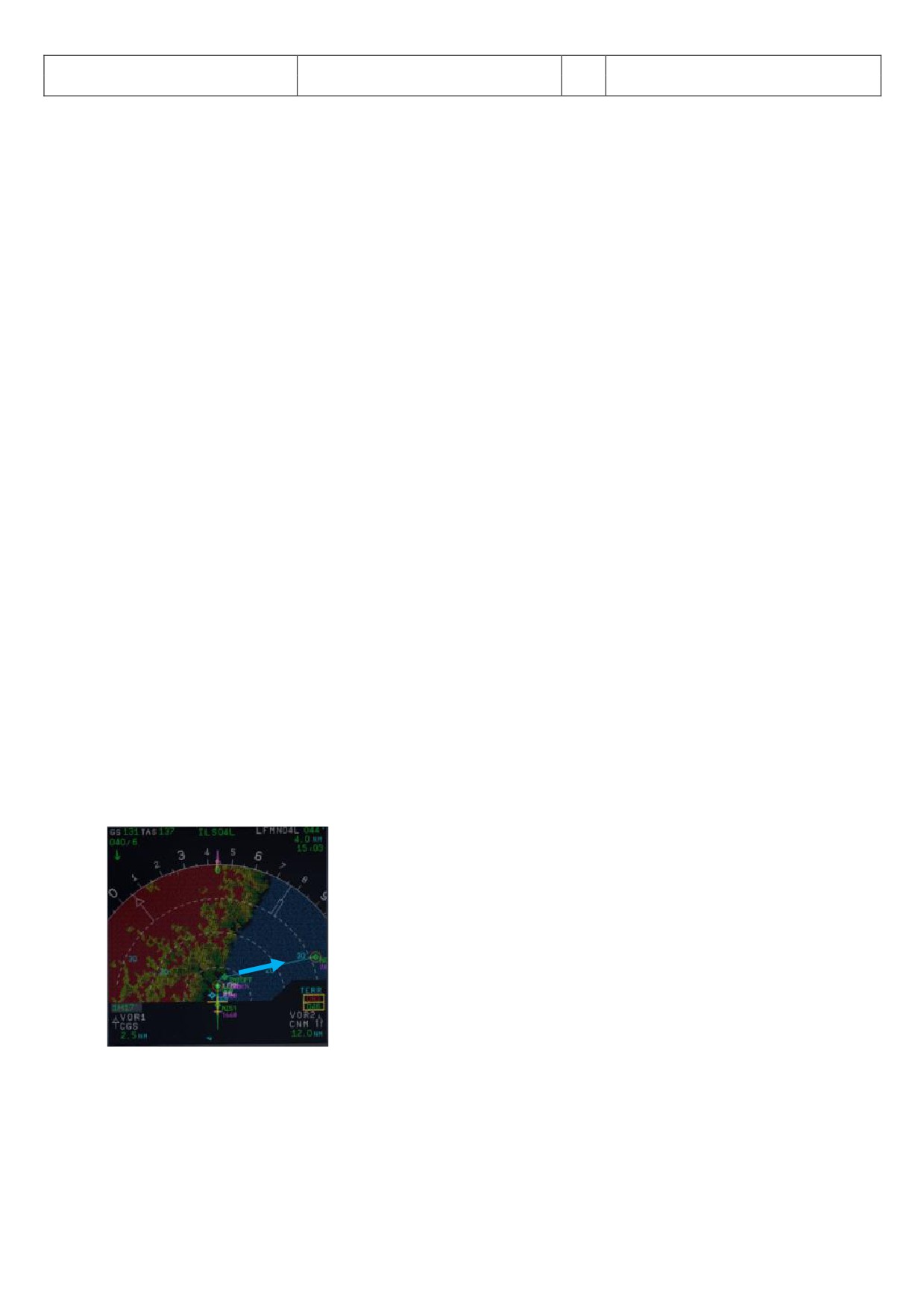
Aerosoft
The Airbus A318/319/320/321 in FSX
Vol
06-01-07 Page 70
Airbus A318/319/320/321
Step-By-Step Tutorial
6
07 April 2015
the runway is blocked by another aircraft or if there is a problem with the aircraft itself just set the
thrust levers to the most forward position = MAN TOGA and this GO AROUND procedure- and
checklist will start automatically. Please fly using the procedure and checklist as in the table above.
B.
“Go Around Flaps”: After this PF call the copilot automatically sets the flaps one position back e. g. in
our case as we used FULL: From FULL to 3.
I.
Thrust Reduction Altitude: When the THR RED altitude is reached (1.512 feet in our example) a
flashing LVR CLB message appears on the FMA (1st column).
J.
Flaps: The copilot sets the flaps back to 1. In our case from 3 to 1.
K.
Thrust Levers: Move the thrust levers back to the CL detent = THR CLB (FMA displays SPEED because
the speed is limited to 200 kts). As the thrust reduces when the levers are moved back to the CL
detent, you should anticipate the pitch reduction caused by this thrust reduction. Take a 10° pitch
angle.
L.
Autopilot: Because for an ILS CAT 1 landing at LFMN LIS04L we switched the autopilot OFF now the
autopilot has be engaged again. If in connection with other landings the autopilot is still set to ON
then the PF just confirms the setting.
M. Green Dot / S-Speed: t “Green Dot / S-Speed the PF calls “Flaps up”
O.
Flaps UP: The copilot sets the flaps to UP.
P.
2nd Autopilot: Automatically set to OFF after the Thrust Reduction Altitude has been reached (if
applicable).
Setting the Thrust Levers to M N TOG the G flight path on the ND changes to “green” (in the MCDU too) and
becomes active. The plane will climb to 2.000 feet which is the GA altitude for the last GA waypoint = NERAS
and automatically follow the GA flight path (for LFMN ILS04L those are the waypoints 320, INTCPT and NERAS).
Also automatically the flight path for another approach (including GA) at the same runway is entered into the
MCDU on the FPLAN pages. This another approach flight plan is divided from the active flight plan by a F-PLAN
DISCONTINUITY and only consists of the final waypoints for ILS04L and does not include any TRANS or VIA
waypoints.
As ATC advises us to fly a holding at NERAS at an altitude of 4.000 feet we have to climb from 2.000 (set GA
ALT) to 4.000 feet. So change the altitude on FCU ALT to 4000 and push the knob. Then the plane will climb to
FL40.
Descent or Climb-to-Altitude On the Infobar you will see the following message: CHANGE FCU ALT FOR NEW
APPROACH OR START APPROACH CL (MCDU OR KEY 1).
Picture 75: ND - G/A flight path for LFMN ILS04L
Before reaching NERAS we will enter a holding into the F-PLAN to wait for further instructions from ATC.
MCDU FPLAN: Scroll to NERAS (should be at the beginning e. g. before the FPLAN DISCONTINUITY) and
push the respective LSK L.
HOLD: Push LSK 3L
INBOUND COURSE: Enter 298 according to the aeronautical charts (LSK 1L)
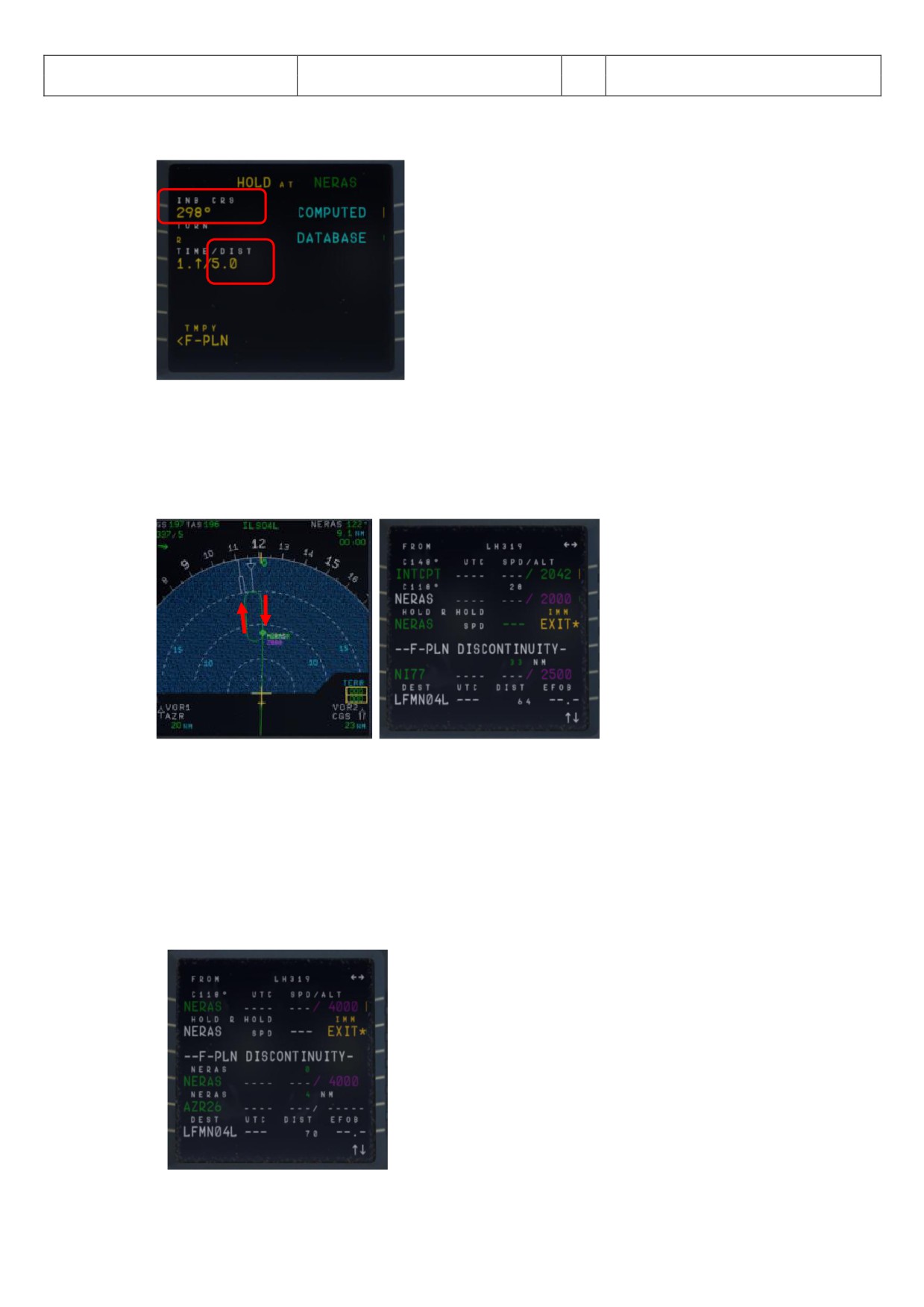
Aerosoft
The Airbus A318/319/320/321 in FSX
Vol
06-01-07 Page 71
Airbus A318/319/320/321
Step-By-Step Tutorial
6
07 April 2015
DISTANCE: Enter “/5.0” as distance of the holding (LSK 3L)
Picture 76: MCDU - F-PLAN - Entering a holding at NERAS
TEMPORARY F-PLAN: Push LSK 6L
TEMPORARY INSERT: Insert the TEMPORARY F-PLAN - Push LSK 6R
“HOLD R” is entered into the FPL N after NERAS (please see picture below).
Picture 77: After entering a holding at NERAS
Now there are two options to continue the flight:
A. Another attempt to land at LFMN ILS04L
Only the FINAL waypoints for LFMN ILS04L (NI77 and NI51) have automatically been added to the
FPLAN.
But we are advised to use TR NS/VI
“NER S” again for our approach. So please push LSK6L,
then ARRIVAL LSK1R and using LSK2L (VIA) select NERAS. Between F-PLAN DISCONTINUITY and
NI77 now the waypoint for the NERAS approach are inserted.
Picture 78: After entering VIA NERAS for new approach
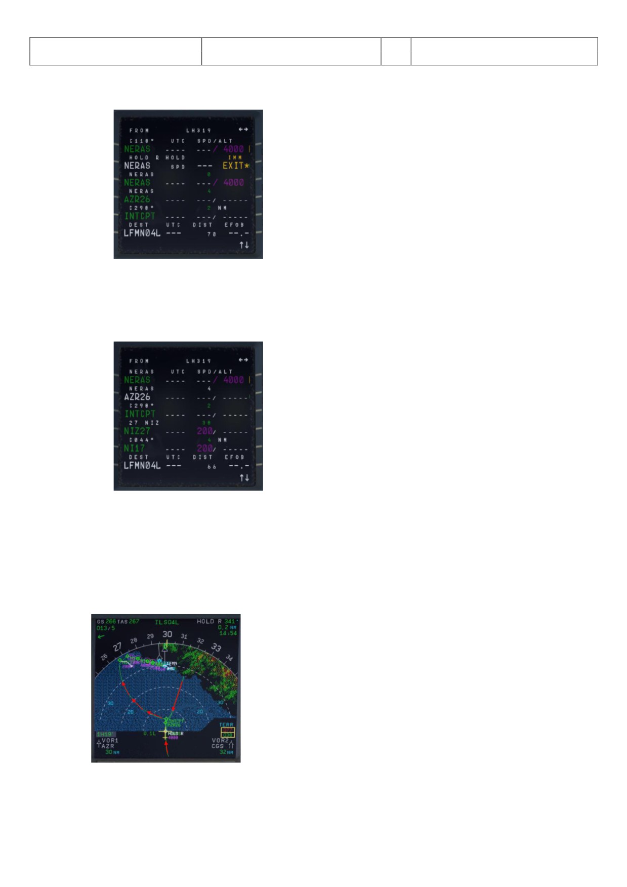
Aerosoft
The Airbus A318/319/320/321 in FSX
Vol
06-01-07 Page 72
Airbus A318/319/320/321
Step-By-Step Tutorial
6
07 April 2015
Delete = CLR the FPLAN-DISCONTINUITY between HOLD R and NERAS (first waypoint for another
approach at LFMN ILS04L).
Picture 79: After deleting F-PLAN DISCONTINUITY
If the F-PLAN DISCONTINUITY is not cleared and NERAS (last waypoint of the GA flight path) is reached
or HOLD R is left, the FMGS will go into PPOS Mode, where it will revert to Basic AP Modes (HDG and
VS/ALT/ALT*).
EXIT HOLD R: Push the respective LSK R on the F-PLAN page to exit the holding
Picture 80: After EXIT the holding
Fly another approach.
s in the “real” irbus there are no ALT/SPD PREDICTIONS available in GA phase. Also, there is no DECEL
point calculated and symbol displayed on the ND during GA phase. The APPR PHASE (MCDU - PERF - APPR)
has to be manually activated as well as previously the APPROACH CL (MCDU or Key 1). In our case start
both after leaving the holding on the way to AZR26.
Picture 81: ND - After activating flight path for another attempt
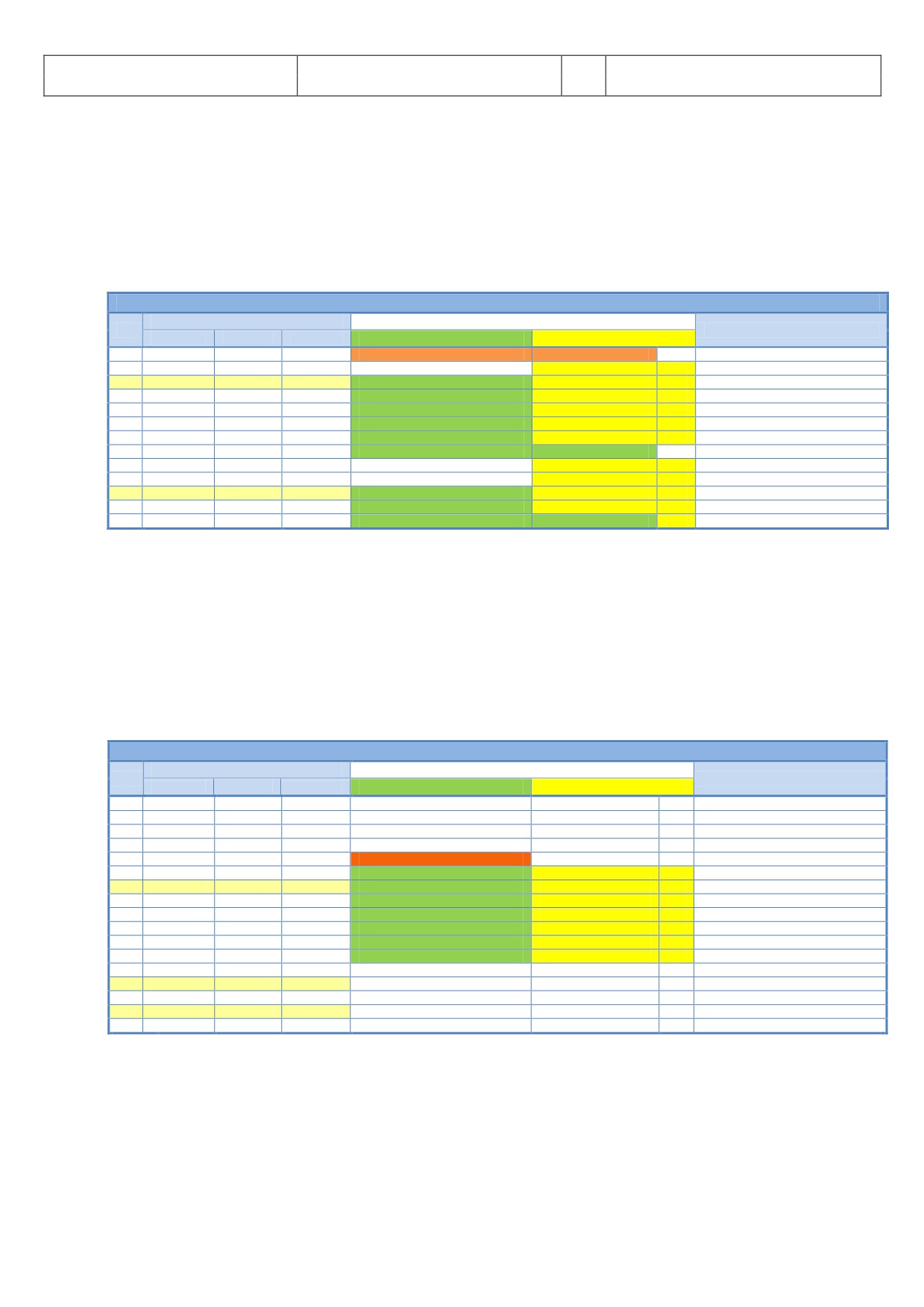
Aerosoft
The Airbus A318/319/320/321 in FSX
Vol
06-01-07 Page 73
Airbus A318/319/320/321
Step-By-Step Tutorial
6
07 April 2015
If there is no ALT change to your next waypoint please start the APPR CL manually (MCDU 2 or from the
keyboard using “1”). As in our case there is no ALT change between NERAS and AZR26 (= 4.000 feet) so
after leaving HOLD R start the APPR CL manually.
B. Diversion to another Airport
Please see chapter 7.2 - Alternate Destinations - for details.
5.24
After Landing
AFTER LANDING
PANEL
ACTION
NO.
REMARK
TYP
PART (Name)
PART (No.)
PF (PILOT FLYING)
PM (PILOT MONITORING)
299
Ground Speed >35 / Dir. to runway > 15 °
Start Checklist / Co-Pilot - if selected
300
GLARESHIELD
CHRONO
7
CHRONO
STOP
Push upper right button
301
OVERHEAD
EXT. LIGHTS
9
NOSE LIGHTS
ON
CoP
302
OVERHEAD
EXT. LIGHTS
9
LANDING LIGHTS
OFF
CoP
303
OVERHEAD
EXT. LIGHTS
9
STROBE LIGHT = OFF or AUTO
If ON = OFF
CoP
304
PEDESTAL
TCAS
10
TCAS MODE SEL
STBY
CoP
305
PEDESTAL
FLAPS
8
FLAPS
RETRACT
CoP
FSX: F6
306
PEDESTAL
ENGINE
5
ENG MODE SEL
NORM
Cop
307
PEDESTAL
WXR
11
WXR: SET system to OFF
SET
Cop
308
EFIS
FD / ILS
3
ILS LOCALIZER (LS)
OFF
CoP
EFIS
309
OVERHEAD
APU
10
APU MASTER and APU START
ON
310
PEDESTAL
SP.BRAKES
6
GRND SPLRS
DISARM
CoP
FSX: /
311
ECAM
WHEEL PAGE
1
BRAKE TEMP all wheels = > 300 degrees
CHECK
Checklist complete
301. Exterior Lights: Set “NOSE” light to „ON“.
309. APU START: Becomes available 10 seconds after starting APU MASTER
AES
Open the AES (CTRL+SHIFT+W) or GSX (CRTL + F12) window. In AES / GSX select the option “F2 -
GSX: Increment Position” until you see the gate position: A14 and then select “F3 - Request Follow-Me to
selected Position”. Follow the car. When you are at the gate and have set the parking brakes to ON
you will hear “Blocks in position” i.e. you have reached the right position.
5.25
Parking
PARKING
PANEL
ACTION
NO.
REMARK
TYP
PART (Name)
PART (No.)
PF (PILOT FLYING)
PM (PILOT MONITORING)
312
PEDESTAL
RADIO
1
ATC (if no AUTO position)
STBY / OFF
313
OVERHEAD
ANTI-ICE
8
ANTI ICE (WING and ENGINES 1&2)
CHECK = OFF
314
PEDESTAL
RADIO
1
GROUND CONTACT
ESTABLISH
If ATC is used
315
PEDESTAL
P.BRAKE
7
PARKING BRAKE ON
SET ON
FSX: CTRL + . (period)
316
PEDESTAL
ENGINE
5
ENG MASTER 1 & 2
OFF
Start Checklist / Co-Pilot - if selected
317
MCDU R
GRND SERV
CHOCKS
SET
CoP
318
PEDESTAL
P.BRAKE
7
PARKING BRAKE
OFF
CoP
FSX: . (period)
319
OVERHEAD
SIGNS
11
SEAT BELTS
OFF
CoP
320
OVERHEAD
EXT. LIGHTS
9
BEACON LIGHT
OFF
CoP
321
OVERHEAD
EXT. LIGHTS
9
TAXI LIGHT.
OFF
CoP
322
OVERHEAD
ANTI-ICE
8
WING & ENGINE ANTI ICE = OFF
CHECK
Cop
323
OVERHEAD
FUEL
2
FUEL PUMPS
OFF
CoP
OFF should appear / Checklist complete
324
MCDU R
GRND SERV
CONES
SET
325
MCDU R
GRND SERV
ESTABLISH EXTERNAL POWER
CONNECT
326
OVERHEAD
EXT POWER
6
EXT. POWER = AVAILABLE
SET TO ON
327
OVERHEAD
APU
10
APU MASTER
SET TO OFF
328
MCDU
MENU
ACFT DOORS
DOORS
OPEN (AS REQUIRED)
318. CHOCKS / PARKING BRAKE: Because the brakes have to cool off after landing, the parking brake can
be released after the chocks have been set. The plane is then just held by the chocks only.
325. EXT POWER: Depending on the situation at the airport direct external power or delivered by a GPU is
used to deliver the power needed. Please select the equivalent. For Vienna we just use EXTERNAL
POWER (no GPU).
327. APU: After the connection to external power is established the APU can be set to OFF.
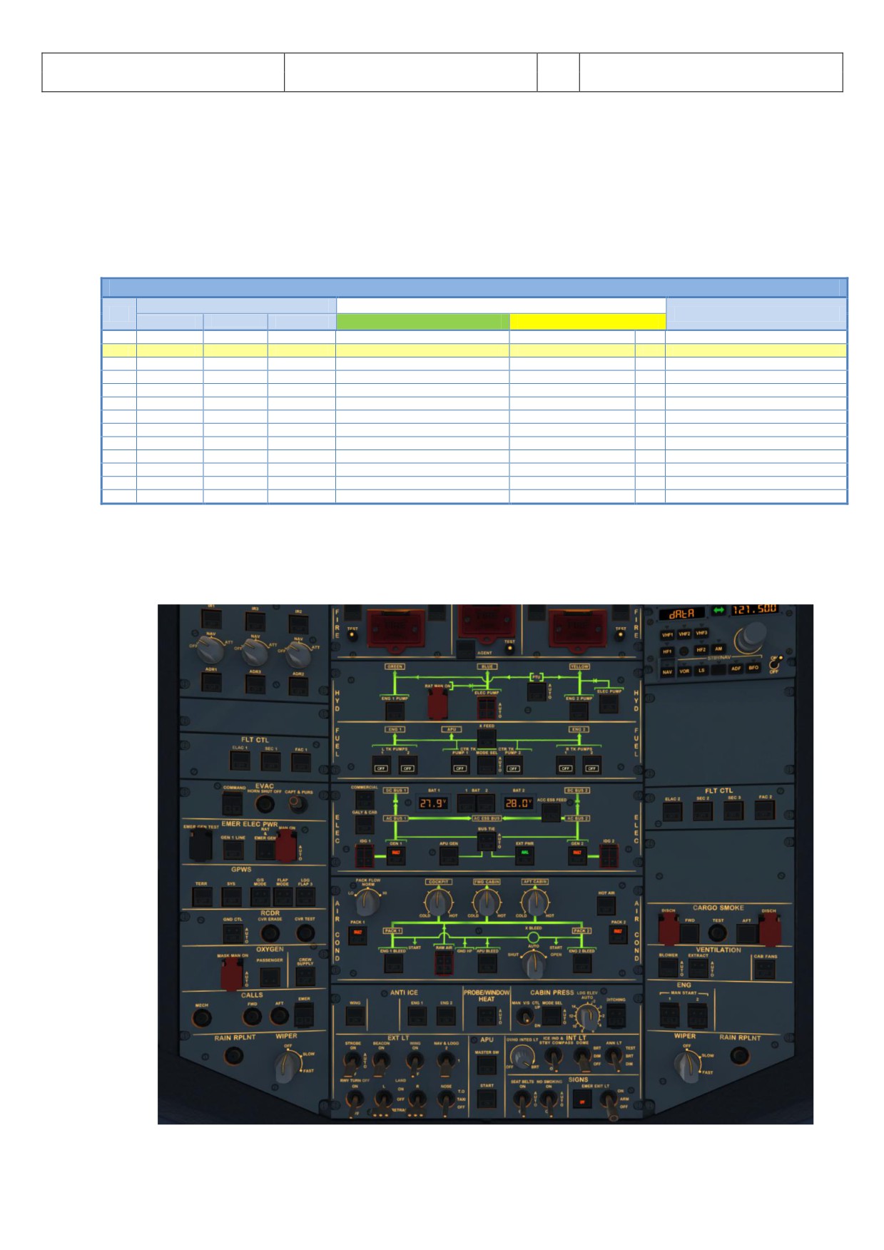
Aerosoft
The Airbus A318/319/320/321 in FSX
Vol
06-01-07 Page 74
Airbus A318/319/320/321
Step-By-Step Tutorial
6
07 April 2015
AES
Open the AES (CTRL+SHIFT+W) or GSX window (CRTL + F12) and select your options.
GSX:
5 Minutes after the “Parking CL” has been finished the complete system (incl. MCDU) is automatically reset
and you are able to prepare for a “turnaround” e. g. starting again with the “Cockpit Preparation CL”. A
specific information is available in the infobar.
5.26
Securing Aircraft
SECURING AIRCRAFT
PANEL
ACTION
NO.
REMARK
TYP
PART (Name)
PART (No.)
PF (PILOT FLYING)
PM (PILOT MONITORING)
329
OVERHEAD
ADIRS
ADIRS (1 + 2 + 3)
OFF
330
OVERHEAD
EXT. LIGHTS
9
NAV. LIGHTS
OFF
331
OVERHEAD
SIGNS
11
NO SMOKING & EMERGENCY LIGHT
OFF
332
MCDU
MENU
ACFT DOORS
DOORS
CLOSE (AS REQUIRED)
333
OVERHEAD
EXT. PWR
6
EXT PWR
AS REQUIRED
334
OVERHEAD
ELEC
5
GEN 1 + 2 (Electric Generators)
PRESS
OFF should appear
335
PEDESTAL
INT. LIGHT
3
INTEG LT
OFF
336
MAIN PANEL
PFD LIGHT
8
SWITCH
OFF
337
MAIN PANEL
ND LIGHT
8
SWITCH
OFF
338
ECAM
DIMMER
4
SWITCH UPPER and LOWER
OFF
339
PEDESTAL
RADIO
1
RADIO CONTROL PANEL
OFF
340
PEDESTAL
TCAS
10
TCAS = STBY
SET
341
OVERHEAD
BATTERIES
4
BAT 1 + 2
OFF
330. Exterior Lights: Switch off all exterior lights.
XXX. Cockpit „COLD DARK“: Now the status of the cockpit should be “COLD DARK”. ll systems and switches
should be “OFF”. Before switching the batteries to OFF the panel should look like in the following
picture:
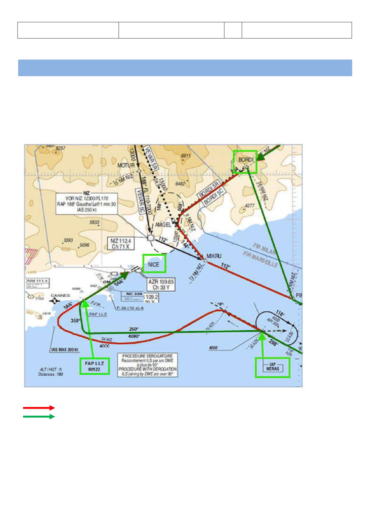
Aerosoft
The Airbus A318/319/320/321 in FSX
Vol
06-01-07 Page 75
Airbus A318/319/320/321
Step-By-Step Tutorial
6
07 April 2015
6. Vector Approach using DIR TO and RADIAL IN
Picture 82: Overhead Panel before switching OFF both batteries
This part of the tutorial uses also the flightplan LOWILFMN01 (Innsbruck to Nice) but covers only the descent from
cruise level and the vector approach into Nice = LFMN 04L. It is mainly based on input from Frank “The Dude” (a RW-
pilot) how a RW vector approach is flown into LFMN ILS 04L.
FLIGHTPATH APPROACH LFMN ILS04L
Picture 83: Vector approach flight path into LFMN
MCDU F-PLAN
Actual flight path
ATC only makes us leave our cruising altitude when they have some sort of ATC competence boundary where they
have to hand us over to somebody else. On our flight to Nice that would be BORDI. This is the ATC border between
Italy and France. The French want us in FL170 when entering their airspace. The reason is that Nice outbound planes
going towards Italian airspace. So the Italian ATC would clear us well ahead of BORDI.
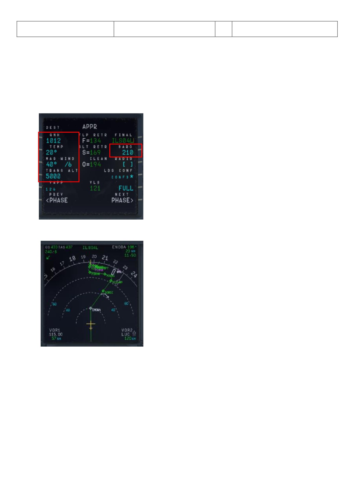
Aerosoft
The Airbus A318/319/320/321 in FSX
Vol
06-01-07 Page 76
Airbus A318/319/320/321
Step-By-Step Tutorial
6
07 April 2015
After passing EVANO we will receive ATC instructions for descent::
o ATC - AUA319 Cleared FL170 - reach latest at BORDI. Call me leaving
o PM - AUA319 Cleared FL170 - reach latest at BORDI. Will call you when leaving
Because we are at FL310 this means a descent of 14000’ equivalent to app. 42 NM (1000’ descent every 3
miles at a V/S of -2500). dding some “reserve” we should therefore start our descent app. 15 NM before
ENOBA.
6.1 Prepare the MCDU PERF APPR page
Picture 84: MCDU PERF APPR page
6.2
20 NM before ENOBA manually start the DESCENT PREPARATION CL
Picture 85: Start of DESC PREP CL
6.3 Set the FCU LT to 17000’.
6.4
15 NM before ENOB initiate descent to 17000’: Push the V/S knob and set the V/S rate to -2500 (FMA
= VS -2500)
Inform ATC that you are leaving your cruise altitude:
o PM - AUA319 left FL310 - descend FL170 at BORDI
o ATC - AUA319 leaving FL310 descend FL170 at BORDI
6.5 We will reach FL170 app. 5 NM before BORDI