Airbus A318/319/320/321. FLIGHT CREW TECHNIQUES MANUAL (2005-2022) - page 11
PROCEDURES
ABNORMAL AND EMERGENCY PROCEDURES
A318/A319/A320/A321
FLIGHT CREW
ELEC
TECHNIQUES MANUAL
INTRODUCTION TO EMERGENCY ELECTRICAL CONFIGURATION
Ident.: PR-AEP-ELEC-00019224.0001001 / 20 MAR 17
Applicable to: ALL
The procedure discussed in this section is the EMERGENCY ELECTRICAL CONFIGURATION.
Whilst it is very unlikely that this failure will be encountered, it is useful:
- To refresh on the technical background
- To recall the general guidelines that must be followed in such a case
- To outline the main available systems according to the electrical power source.
TECHNICAL BACKGROUND
Ident.: PR-AEP-ELEC-00019225.0002001 / 25 JUL 17
Applicable to: ALL
The emergency electrical configuration is due to the loss of AC BUS 1 and 2. The RAT extends
automatically. This powers the blue hydraulic circuit which drives the emergency generator. The
emergency generator supplies both AC and DC ESS BUS.
Below 125 kt, the RAT stalls and the emergency generator is no longer powered. The emergency
generation network is automatically transferred to the batteries and AC SHED ESS and DC SHED
ESS BUS are shed.
Below 100 kt, the DC BAT BUS is automatically connected and below 50 kt, the AC ESS BUS is
shed.
GENERAL GUIDELINES
Ident.: PR-AEP-ELEC-00019226.0004001 / 04 JUN 19
Applicable to: ALL
As only PFD1 is available, the left hand seat pilot becomes PF. Once a safe flight path is established,
and the aircraft is under control, ECAM actions will be carried out.
This is a serious emergency and ATC should be notified using appropriate phraseology ("MAYDAY").
Although the ECAM displays LAND ASAP in red, it would be unwise to attempt an approach at a
poorly equipped airfield in marginal weather. However, prolonged flight in this configuration is not
recommended.
AP/FD and ATHR are lost. The flight is to be completed manually in alternate and then, when gear
down, in direct law. Crews should be aware that workload is immediately greatly increased.
As only the EWD is available, disciplined use of the ECAM Control Panel (ECP) is essential.
Consideration should be given to starting the APU as indicated by the ECAM and taking into account
the probability to restore using APU generator.
A clear reading of STATUS is essential to assess the aircraft status and properly sequence actions
during the approach.
PIA A318/A319/A320/A321 FLEET
PR-AEP-ELEC P 1/2
FCTM
A to C →
04 SEP 19
PROCEDURES
ABNORMAL AND EMERGENCY PROCEDURES
A318/A319/A320/A321
FLIGHT CREW
ELEC
TECHNIQUES MANUAL
The handling of this failure is referred to as a "complex procedure". A summary for handling the
procedure is included in the QRH, which will be referred to upon completion of the ECAM procedure.
The ELEC EMER CONFIG SYS REMAINING list is available in QRH.
When landing gear is down, flight control law reverts to direct law.
The approach speed must be at least min RAT speed (140 kt) to keep the emergency generator
supplying the electrical network.
The BSCU are lost. Consequently, the NWS and anti skid are lost. Alternate braking with yellow
hydraulic pressure modulation up to 1 000 PSI will be used. Additionally, reversers are not available.
RA 1+2 are lost with their associated call out. Call out will be made by PM.
Approaching 50 kt during the landing roll, all display units will be lost.
REMAINING SYSTEMS
Ident.: PR-AEP-ELEC-00019227.0001001 / 20 MAR 17
Applicable to: ALL
The electrical distribution has been designed to fly, navigate, communicate and ensure passengers
comfort. The ELEC EMER CONFIG SYS REMAINING list is available in QRH. The significant
remaining systems are:
Significant remaining systems in ELEC EMER CONFIG
FLY
PFD1, alternate law
NAVIGATE
ND1, FMGC1, RMP1, VOR1/ILS1, DME1
COMMUNICATE
VHF1, HF1, ATC1
On BAT, some additional loads are lost such as FAC1 and FMGC1.
PIA A318/A319/A320/A321 FLEET
PR-AEP-ELEC P 2/2
FCTM
← C to D
04 SEP 19
PROCEDURES
ABNORMAL AND EMERGENCY PROCEDURES
A318/A319/A320/A321
FLIGHT CREW
ENG
TECHNIQUES MANUAL
ENGINE ABNORMAL RESPONSE
Ident.: PR-AEP-ENG-00018094.0001001 / 12 JUL 18
Applicable to: ALL
Most engine malfunctions are taken into account by one or several ECAM alerts that warn the flight
crew and provide the flight crew with the actions to perform. However, some engine malfunctions
may not trigger an ECAM alert. These engine malfunctions may require some knowledge and the
analysis of the flight crew, so that the flight crew can recognize, understand, and manage them.
When the flight crew identifies an abnormal parameter, the flight crew should use all the information
available to analyze the engine malfunction. The flight crew should not consider only this abnormal
parameter to perform their analysis.
If possible, the flight crew should keep the engine running in flight. Except if a procedure requires an
engine shutdown, it is usually preferable to keep the engine running. Even at idle, the engine powers
the hydraulic, electric, and bleed systems.
In addition, if the flight crew is not sure which engine has a malfunction, the flight crew should keep
the engines running. If really damaged, the affected engine will eventually fail.
Before approach, if the engine response remains abnormal, the flight crew decides to keep the
engine running or to shut it down taking into account the aircraft controllability and the flight
conditions.
ALL ENGINES FAILURE
Ident.: PR-AEP-ENG-A-00020207.0002001 / 20 MAR 17
Criteria: 31-1492, P14629, SA
1 Applicable to: MSN 02155-02719, 02789-02944, 03060, 05152-07792
INTRODUCTION
The all engines failure is the situation where the aircraft entirely or partially loses engine thrust,
and is no longer able to maintain level flight.
The all engines failure can be identified by the Flight Warning Computer (FWC) or by the flight
crew:
1. In most cases, the FWC detects an all engines failure condition and displays the ENG ALL
ENGINES FAILURE ECAM alert
2. In some cases, the FWC does not detect the all engines failure condition. In the case of partial
loss of thrust (no engine flame out) on one or more engines, the residual N2 may remain slightly
above the ENG 1(2) FAIL alert threshold.
Even if the ENG ALL ENGINES FAILURE alert is not triggered, the flight crew must rapidly decide
to apply either the ALL ENG FAIL QRH procedure, or the EMER LANDING QRH procedure,
depending on their assessment of the situation. If the flight crew considers there is sufficient time
to attempt an engine relight, they must apply the ALL ENG FAIL QRH procedure. However, if
the flight crew considers there is not sufficient time to attempt an engine relight, they must apply
PIA A318/A319/A320/A321 FLEET
PR-AEP-ENG P 1/26
FCTM
A to B →
12 JAN 22
PROCEDURES
ABNORMAL AND EMERGENCY PROCEDURES
A318/A319/A320/A321
FLIGHT CREW
ENG
TECHNIQUES MANUAL
the EMER LANDING QRH procedure. For more information, Refer to PR-AEP-MISC EMER
LANDING.
Ident.: PR-AEP-ENG-A-00020207.0001001 / 20 MAR 17
Criteria: SA
Applicable to: MSN 02758, 03031, 03097-04392
INTRODUCTION
The all engines failure is the situation where the aircraft entirely or partially loses engine thrust,
and is no longer able to maintain level flight.
The all engines failure can be identified by the Flight Warning Computer (FWC) or by the flight
crew:
1. In most cases, the FWC detects an all engines failure condition and displays the ENG DUAL
FAILURE ECAM alert
2. In some cases, the FWC does not detect the all engines failure condition. In the case of partial
loss of thrust (no engine flame out) on one or more engines, the residual N2 may remain slightly
above the ENG 1(2) FAIL alert threshold.
Even if the ENG DUAL FAILURE alert is not triggered, the flight crew must rapidly decide to
apply either the ENG DUAL FAILURE QRH procedure, or the EMER LANDING QRH procedure,
depending on their assessment of the situation. If the flight crew considers there is sufficient time
to attempt an engine relight, they must apply the ENG DUAL FAILURE QRH procedure. However,
if the flight crew considers there is not sufficient time to attempt an engine relight, they must apply
the EMER LANDING QRH procedure. For more information, Refer to PR-AEP-MISC EMER
LANDING.
Ident.: PR-AEP-ENG-A-00020797.0002001 / 20 MAR 17
Criteria: 31-1492, P14629, SA
2 Applicable to: MSN 02155-02719, 02789-02944, 03060, 05152-07792
TECHNICAL BACKGROUND
An all engines failure situation mainly results in an emergency electrical configuration (Refer to
PR-AEP-ELEC Introduction to Emergency Electrical Configuration), and in the loss of the green
and yellow hydraulic systems.
ELECTRICAL CONFIGURATION
In the case of an all engines failure:
- All the AC busbars are lost
- The RAT automatically deploys to supply the emergency generator (EMER GEN or CSM/G).
The EMER GEN supplies both the AC ESS and the DC ESS bus bars.
PIA A318/A319/A320/A321 FLEET
PR-AEP-ENG P 2/26
FCTM
← B →
12 JAN 22
PROCEDURES
ABNORMAL AND EMERGENCY PROCEDURES
A318/A319/A320/A321
FLIGHT CREW
ENG
TECHNIQUES MANUAL
The AC ESS SHED bus bar and DC ESS SHED bus bar are:
- Supplied by the CSM/G
- Shed, when the aircraft is supplied only by batteries.
The emergency generator can supply all the electrical loads that are necessary for the
remainder of the flight. The EMER GEN, that is connected to the network, remains connected
even if all the main generators are recovered (following engines relight), or if the APU generator
is connected.
Below FL 250, if the flight crew can start the APU, the normal electrical configuration partly
recovers.
APU START
If fuel remains, the flight crew should attempt an APU start regardless of the RAT type in
order to recover cabin pressurization, additional electrical power and have bleed available for
a starter-assisted relight, if necessary.
APU start attempts use the aircraft batteries and reduce batteries load (each APU start
attempt reduces flight time on batteries by about 3 and a half minutes). Total flight time on
batteries is more than 30 min.
HYDRAULIC GENERATION
The green and yellow hydraulic systems are lost. The RAT automatically deploys to pressurize
the blue hydraulic system.
When the hydraulic power is lost, the right aileron is lost and goes to its zero hinge moment
position. There is enough authority to balance this roll, but instead of flying with permanent stick
deflection in roll, the PF may use the rudder trim to generate sideslip and therefore compensate
for this upfloating aileron. When the APU generator is connected, the control of the right aileron
is restored due to the recovery of ELAC 2.
As hydraulic power is only available from the RAT, the PF should avoid large and rapid rudder
deflections.
If engine windmilling is sufficient, additional hydraulic power may be recovered.
Ident.: PR-AEP-ENG-A-00020797.0001001 / 20 MAR 17
Criteria: SA
Applicable to: MSN 02758, 03031, 03097-04392
TECHNICAL BACKGROUND
An all engines failure situation mainly results in an emergency electrical configuration (Refer to
PR-AEP-ELEC Introduction to Emergency Electrical Configuration), and in the loss of the green
and yellow hydraulic systems.
PIA A318/A319/A320/A321 FLEET
PR-AEP-ENG P 3/26
FCTM
← B →
12 JAN 22
PROCEDURES
ABNORMAL AND EMERGENCY PROCEDURES
A318/A319/A320/A321
FLIGHT CREW
ENG
TECHNIQUES MANUAL
ELECTRICAL CONFIGURATION
In the case of an all engines failure:
- All the AC busbars are lost
- The RAT automatically deploys to supply the emergency generator (EMER GEN or CSM/G).
The EMER GEN supplies both the AC ESS and the DC ESS bus bars.
The AC ESS SHED bus bar and DC ESS SHED bus bar are:
- Supplied by the CSM/G
- Shed, when the aircraft is supplied only by batteries.
The emergency generator can supply all the electrical loads that are necessary for the
remainder of the flight. The EMER GEN, that is connected to the network, remains connected
even if all the main generators are recovered (following engines relight), or if the APU generator
is connected.
Below FL 250, if the flight crew can start the APU, the normal electrical configuration partly
recovers.
HYDRAULIC GENERATION
The green and yellow hydraulic systems are lost. The RAT automatically deploys to pressurize
the blue hydraulic system.
When the hydraulic power is lost, the right aileron is lost and goes to its zero hinge moment
position. There is enough authority to balance this roll, but instead of flying with permanent stick
deflection in roll, the PF may use the rudder trim to generate sideslip and therefore compensate
for this upfloating aileron. When the APU generator is connected, the control of the right aileron
is restored due to the recovery of ELAC 2.
As hydraulic power is only available from the RAT, the PF should avoid large and rapid rudder
deflections.
If engine windmilling is sufficient, additional hydraulic power may be recovered.
PIA A318/A319/A320/A321 FLEET
PR-AEP-ENG P 4/26
FCTM
← B →
12 JAN 22
PROCEDURES
ABNORMAL AND EMERGENCY PROCEDURES
A318/A319/A320/A321
FLIGHT CREW
ENG
TECHNIQUES MANUAL
Ident.: PR-AEP-ENG-A-00020798.0003001 / 12 JUL 18
Criteria: 31-1334, 31-1414, 31-1492, P10383, P14629, SA
3 Applicable to: MSN 02155-02719, 02789-02944, 03060, 05152-07792
GENERAL PHILOSOPHY
GENERAL PHILOSOPHY
PIA A318/A319/A320/A321 FLEET
PR-AEP-ENG P 5/26
FCTM
← B →
12 JAN 22
PROCEDURES
ABNORMAL AND EMERGENCY PROCEDURES
A318/A319/A320/A321
FLIGHT CREW
ENG
TECHNIQUES MANUAL
Following an all engines failure, the cockpit indications change significantly, because the
generators disconnect from the AC and DC bus bars:
- AP, FD, and A/THR are lost
- Aircraft operates in alternate law
- F/O PFD and F/O ND are lost.
When the flight crew detects an all engines failure condition, they must apply the golden rule #1
(Fly, Navigate, Communicate : In this order and with the appropriate tasksharing). CM1 (left-hand
seat pilot) is PF since only PFD1 is available. CM1 must immediately take over control of the
aircraft, and must establish a safe flight path.
After the PF establishes a safe flight path, the PM should perform the ECAM actions. The EWD
remains available. The PM (F/O side) can display the SD pages on EWD by pressing and holding
the associated system page pushbutton on the ECP.
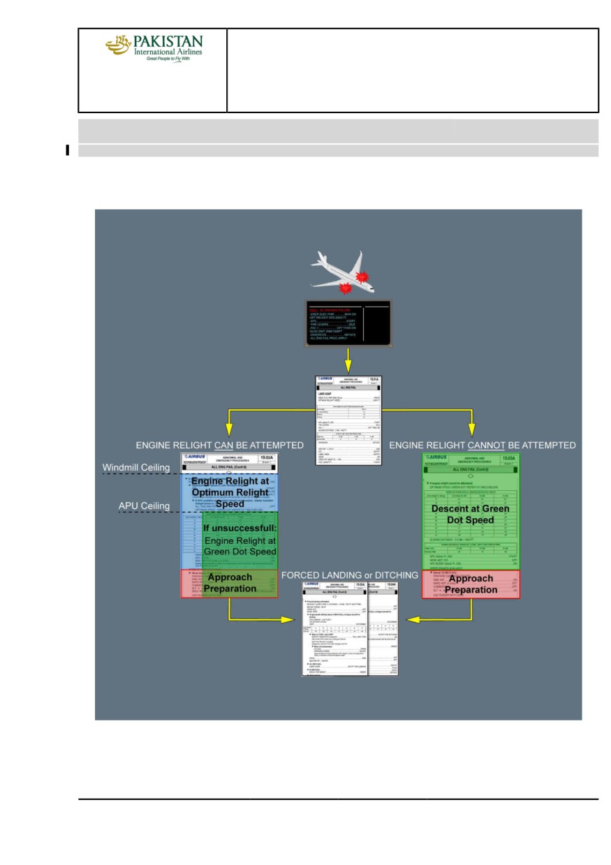
The ENG ALL ENGINES FAILUREalert provides the first key steps of the procedure and then
directs the flight crew to the ALL ENG FAIL QRH procedure.
Due to the advantages of the Windmill relight (available for a large altitude range, simultaneous
relight attempts on all engines, relight attempts not dependent on the technical condition of the
aircraft systems) compared to the starter-assisted relight (using the APU bleed), the ALL ENG
FAIL QRH procedure promotes the Windmill relight for all altitudes of the certified relight envelope.
As a result, the optimum speed for Windmill engine relight is displayed on the ECAM when the
ENG ALL ENGINES FAILURE alert triggers. This optimum relight speed depends on the engine
type and enables an immediate Windmill relight without an excessive aircraft descent rate within
the whole Windmill relight envelope.
Depending on the circumstances, in order to reach the optimum relight speed, the flight crew
may increase the speed during descent. However, the flight crew should keep in mind that, in
alternate law, the overspeed protection is lost and that the aircraft speed and Mach upper limits
are reduced.
If the all engines failure is subsequent to a flight through volcanic ashes, the situation may
be associated to unreliable speed indications. Therefore, the QRH procedure includes
complementary information compared to the ECAM and provides the pitch attitude that the PF
must maintain to target the optimum relight speed.
The flight crew must set the thrust levers to the Idle detent in order to avoid any thrust power surge
when the engine relights.
The gliding distance displayed on the ECAM enables to roughly estimate the aircraft range
as a function of the aircraft altitude at the optimum relight speed without wind. As a result, the
flight crew should be able to rapidly assess the situation and determine their landing strategy
if the engines do not relight. However, this gliding distance figure is an envelope value. As a
result, depending on actual parameters, the actual gliding distance may differ. After their range
assessment, the PF should then initiate the diversion to an accessible runway, or determine the
most appropriate area for a forced landing or ditching.
PIA A318/A319/A320/A321 FLEET
PR-AEP-ENG P 6/26
FCTM
← B →
12 JAN 22
PROCEDURES
ABNORMAL AND EMERGENCY PROCEDURES
A318/A319/A320/A321
FLIGHT CREW
ENG
TECHNIQUES MANUAL
When time permits, the flight crew must transmit an emergency message to ATC using VHF1.
Depending on the exact situation, assistance may be available from ATC (e.g. position of other
aircraft, safe direction, closest airport, etc…).
Different causes may lead to a thrust loss so that altitude cannot be maintained. However, fuel
starvation is one of the most probable cause. As a result, the ALL ENG FAIL QRH procedure
requests the flight crew to check the on-board fuel quantity in order to ensure that the aircraft is not
experiencing a fuel starvation issue that will prevent engines relight. Then, depending on the flight
crew assessment of the situation, they must determine whether engines relights can be attempted,
or not. The ALL ENG FAIL QRH procedure addresses all situations and provides all necessary
procedure steps until the touchdown if the engines do not relight. As a consequence, the QRH
procedure includes the ditching or the forced landing procedures adapted to the all engines failure
situation.
IF ENGINE RELIGHT CAN BE ATTEMPTED
If the flight crew can attempt engines relights, ALL ENG FAIL QRH procedure provides all
necessary information and conditions (e.g. Windmill ceiling) to perform successful engines
relights. As already indicated, the ALL ENG FAIL QRH procedure promotes windmill relight. If
the first relight attempt is not successful, the flight crew should repeat windmill relight attempts
on all engines until successful.
However, if none of the engines relights after several attempts using windmill, below FL 200,
the flight crew can take advantage of the APU bleed air, if available, to attempt starter-assisted
engine relights. If the APU bleed is used, the flight crew must fly at a speed below the optimum
windmill speed to enable the FADEC to perform a starter-assisted engine relight. The flight crew
can reduce speed to the green dot speed to minimize the aircraft descent rate. Green dot for all
engines inoperative is displayed on the left PFD. However, the ALL ENG FAIL QRH procedure
includes a table of green dot speed with all engines inoperative as a function of the aircraft
weight and altitude.
If the APU bleed is used, the flight crew can attempt a relight on only one engine at a time.
Regardless of the relight procedure (Windmill, or using the APU bleed), engine master levers
must be set to OFF for 30 s in order to ventilate the combustion chamber of the engine between
two relight attempts.
Depending on the engine state and environmental conditions, the engine relight may take
time. As long as the engine parameters continuously increase and reach idle values without
exceeding limits, the flight crew should not abort the relight attempt.
IF ENGINE RELIGHT CANNOT BE ATTEMPTED
If the flight crew considers that they cannot attempt engines relights (e.g. engine damage,
fuel starvation), they should apply directly the applicable section of the ALL ENG FAIL QRH
procedure. This section requires flying at green dot speed, that is the best lift-to-drag ratio
speed in order to maximize the remaining time for cabin preparation and distance flown. This
PIA A318/A319/A320/A321 FLEET
PR-AEP-ENG P 7/26
FCTM
← B →
12 JAN 22
PROCEDURES
ABNORMAL AND EMERGENCY PROCEDURES
A318/A319/A320/A321
FLIGHT CREW
ENG
TECHNIQUES MANUAL
section of the ALL ENG FAIL QRH procedure provides a table of green dot speed with all
engines inoperative as a function of the aircraft weight and altitude. If fuel remains, the flight
crew should start the APU below FL 250 to improve electrical power supply and recover CM2
display units. The flight crew should also use APU bleed below FL 200 to recover the cabin
pressurization.
APPROACH AND LANDING
When conditions permit, the flight crew should continue engine relights attempts using the APU
bleed.
If no engine relights and depending on the situation, the flight crew should prepare the aircraft
either for a ditching, or for a forced landing, even if a runway can be reached. Ditching and forced
landing procedures are very similar, except for the landing gear that must be up for a ditching.
The flight crew should pay attention to the time to manage the QRH procedure. An efficient
procedure application is important to fully configure the aircraft for the ditching or the forced
landing. Some items at the end of the procedure are time consuming (e.g. slats extension).
The flight crew must notify the cabin crew of a forced landing or ditching, in order to prepare the
cabin. For approach, only slats are available.
FORCED LANDING
If the flight crew expects a forced landing, they must extend the landing gear to absorb some
energy at touchdown, even if the landing is planned out of a runway. The landing gear must be
extended by gravity.
Since the trajectory is significantly modified when the aircraft is configured for landing (due to
slat/flap and landing gear extension), the descent slope is provided at the beginning of the “Forced
landing” section of the procedure to help flight crew anticipate this modification.
For the PF, during the initial and final approach, the main concern is the aircraft energy
management.
The PF should maintain aircraft path higher than in a normal approach because there is no engine
to manage energy.
If the aircraft is too high to reach the landing area, PF may use the remaining speed brakes to
generate drag and increase the descent rate, if needed.
When the flight crew selects a runway, they may perform a visual approach, if possible.
When on ground, the flight crew can use the brake pedals. The brake accumulator provides the
hydraulic power to the brakes, but the number of brake applications is limited. As the A-SKID is not
available, the brake pressure should be limited to 1 000 PSI. As the nose wheel steering is lost,
the PF must use the rudder at high speed in order to maintain the runway axis, if applicable. At
lower speeds, the PF may use differential braking to maintain the selected axis but avoid brake
release for accumulator endurance purpose.
PIA A318/A319/A320/A321 FLEET
PR-AEP-ENG P 8/26
FCTM
← B →
12 JAN 22
PROCEDURES
ABNORMAL AND EMERGENCY PROCEDURES
A318/A319/A320/A321
FLIGHT CREW
ENG
TECHNIQUES MANUAL
DITCHING
Just before ditching, the flight crew must set the DITCHING pb to ON in order to close all valves
under the aircraft.
Then, the flight crew must touchdown with a minimum aircraft vertical speed. The flight crew
should maintain the optimum pitch flare until the impact on the water, and should keep the wings
level.
RELIGHT OF ONE ENGINE
When at least one engine relights, the ENG ALL ENGINES FAILURE alert disappears and the
ENG 1(2) FAIL alert is triggered on the E/WD for the remaining engines.
The ENG 1(2) FAIL procedure requests to consider the application of the abnormal ENG
RELIGHT In Flight QRH procedure.
The ENG RELIGHT In Flight QRH procedure enables to attempt either a windmilling start, or a
starter assisted engine relight with the bleed of the other engine.
The flight crew can decide at any time to stop the ENG RELIGHT In Flight QRH procedure, if the
situation requires (e.g. remaining time and distance to fly), and to continue with other ECAM alerts
or QRH procedures, if any.
When at least one engine is recovered, AC 1, DC 1, AC 2 and DC 2 are recovered and normal
electrical configuration is restored except, that AC ESS BUS bar and DC ESS BUS bars remain
supplied by the emergency generator.
When at least one engine is recovered, green, yellow and blue hydraulic systems are restored:
- Green and yellow systems due to the engine and associated EDP recovery, and the other
hydraulic system by means of the PTU operation
- Blue hydraulic system is recovered as the electrical supply of the blue electric pump is restored.
Ident.: PR-AEP-ENG-A-00020798.0002001 / 20 MAR 17
Criteria: 31-1334, 31-1414, P10383, SA
Applicable to: MSN 02758, 03031, 03097-04392
GENERAL PHILOSOPHY
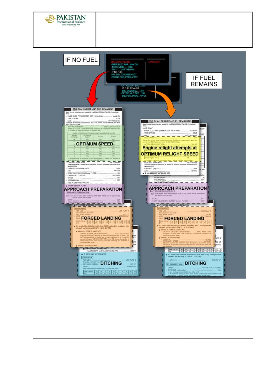
The ECAM provides the first immediate actions to be performed, then refers to two different
QRH procedures: ENG DUAL FAILURE with FUEL REMAINING or ENG DUAL FAILURE
with NO FUEL REMAINING procedures. Consequently, the flight crew must first apply the
steps displayed on the ECAM, then apply the appropriate QRH procedure depending whether
fuel is remaining or not. These QRH procedures are optimized to cope with each situation by
providing corresponding OPERATING SPEEDS and required procedures until landing, including
APPROACH PREPARATION, FORCED LANDING and DITCHING.
PIA A318/A319/A320/A321 FLEET
PR-AEP-ENG P 9/26
FCTM
← B →
12 JAN 22
PROCEDURES
ABNORMAL AND EMERGENCY PROCEDURES
A318/A319/A320/A321
FLIGHT CREW
ENG
TECHNIQUES MANUAL
In the fuel remaining case,
• The actions should be commenced, with attention to the optimum relight speed without starter
assist (with wind milling). If there is no relight within 30 s, the ENG DUAL FAILURE with FUEL
REMAINING QRH procedure orders engine masters off for 30 s. This is to permit ventilation of
the combustion chamber. Then, the engine masters may be set ON again. Without starter assist
(wind milling), this can be done at the same time.
• If the crew wants to take credit of the APU bleed air, the APU should be started below FL 250.
Below FL 200, an engine relight should be attempted with starter assist (using the APU bleed).
• Green dot, which corresponds to the optimum relight speed with starter assist, is displayed on
the left PFD. With starter assist (APU bleed), only one engine must be started at a time.
PIA A318/A319/A320/A321 FLEET
PR-AEP-ENG P 10/26
FCTM
← B →
12 JAN 22
PROCEDURES
ABNORMAL AND EMERGENCY PROCEDURES
A318/A319/A320/A321
FLIGHT CREW
ENG
TECHNIQUES MANUAL
PIA A318/A319/A320/A321 FLEET
PR-AEP-ENG P 11/26
FCTM
← B
12 JAN 22
PROCEDURES
ABNORMAL AND EMERGENCY PROCEDURES
A318/A319/A320/A321
FLIGHT CREW
ENG
TECHNIQUES MANUAL
ENGINE FAILURE - GENERAL
Ident.: PR-AEP-ENG-00016338.0001001 / 20 MAR 17
Applicable to: ALL
An engine flameout can be due to many reasons, for example:
- Fuel starvation
- Encounter with volcanic ash, sand or dust clouds
- Heavy rain, hail, or icing
- Bird strike
- Engine stall
- Engine control system malfunction.
An engine flameout may trigger an ECAM alert.
The flight crew can detect an engine flameout without damage by a rapid decrease of EPR/N1, N2,
N3 , EGT and FF.
The flight crew can suspect engine damage, if the flight crew observes two or more of the following
symptoms:
- Rapid increase of the EGT above the red line
- Important mismatch of the rotor speeds, or absence of rotation
- Significant increase of aircraft vibrations, or buffeting, or both vibrations and buffeting
- Hydraulic system loss
- Repeated, or not controllable engine stalls.
ENGINE FAILURE AT LOW SPEED (ON GROUND)
Ident.: PR-AEP-ENG-00018095.0001001 / 17 MAY 21
Applicable to: ALL
If an engine failure occurs at low speed, the resultant yaw may be significant, leading to rapid
displacement from the runway center line.
To regain or maintain directional control on the runway, it is necessary:
- To immediately reduce both thrust levers to IDLE, which will reduce the thrust asymmetry caused
by the failed engine
- To select both reversers irrespective of which engine has failed
- To use rudder pedal for directional control, supplemented by symmetrical or differential braking if
needed.
The steering hand-wheels may be used when taxi speed is reached.
Note:
1. If rudder pedal input and differential braking are needed, apply both on the same side
2. Below 72 kt, the ground spoilers will not deploy and the auto brake will not activate.
PIA A318/A319/A320/A321 FLEET
PR-AEP-ENG P 12/26
FCTM
C to D
12 JAN 22
PROCEDURES
ABNORMAL AND EMERGENCY PROCEDURES
A318/A319/A320/A321
FLIGHT CREW
ENG
TECHNIQUES MANUAL
ENGINE FAILURE AFTER V1
Ident.: PR-AEP-ENG-00018096.0001001 / 03 NOV 21
Applicable to: ALL
AIRCRAFT HANDLING
If an engine fails after V1, the flight crew must continue the takeoff. The essential and primary
tasks are associated with the aircraft handling. The flight crew must stabilize the aircraft at the
correct pitch and airspeed, and establish the aircraft on the correct flight path before the beginning
of the ECAM procedure.
ON THE GROUND:
The flight crew should use the rudder conventionally to maintain the aircraft on the runway
centerline.
At VR, the flight crew should rotate the aircraft using a continuous pitch rate of approximately
3 °/s towards an initial pitch attitude of 12.5 °. The combination of high FLEX temperatures and
low VR speeds requires precise handling during the rotation and liftoff. The 12.5 ° pitch target
will ensure the aircraft becomes airborne.
WHEN SAFELY AIRBORNE:
The flight crew should then follow the SRS orders that may request a lower pitch attitude in
order to obtain the target speed. If an engine failure occurs after liftoff, the SRS targets the
speed at which the failure occurred (limited between V2 and V2 +15 kt).
In the case of an engine failure at takeoff, the blue beta target appears instead of the usual
sideslip indication on the PFD (Refer to FCOM/DSC-27-20-10-50 Sideslip Target). The lateral
normal law will react to a detected thrust asymmetry and command some rudder surface
deflection to minimize the sideslip (there is no feedback of this command to the pedals).
Therefore, laterally, the aircraft is a stable platform and no rush is required to use the rudder
pedals. However, since the lateral normal law does not order the entire rudder surface
deflection, the flight crew must adjust the rudder pedals as usual to center the beta target in
order to optimize the climb performance.
The flight crew should control the heading as usual with the bank angle. The flight crew should
accelerate if it is not possible to center the beta target by applying full rudder. The flight crew
should use the rudder trim to gradually relieve the pressure from the rudder pedals while
keeping the beta target centered. When the aircraft is properly trimmed, the PF should engage
the AP.
When the AP is engaged the rudder trim is managed via the AP, therefore:
• Manual rudder trim command is inhibited
• The flight crew should release any pressure on the rudder pedals.
PIA A318/A319/A320/A321 FLEET
PR-AEP-ENG P 13/26
FCTM
E →
12 JAN 22
PROCEDURES
ABNORMAL AND EMERGENCY PROCEDURES
A318/A319/A320/A321
FLIGHT CREW
ENG
TECHNIQUES MANUAL
Note:
If a rudder pedal deflection is maintained or applied after AP engagement, the AP may
disengage.
PERFORMANCE CONSIDERATIONS
If the climb and/or acceleration performance of the aircraft is less than expected, the flight crew
should confirm that the landing gear has been selected up and consider the use of TOGA thrust,
keeping in mind the following:
- For a FLEX takeoff, setting the operating engine to TOGA provides an additional performance
margin but is not a requirement of the reduced thrust takeoff certification. The application of
TOGA very rapidly supplies a large thrust increase but this comes with a significant increase in
yawing moment and an increased pitch rate. The selection of TOGA restores thrust margins but
it may increase the workload in aircraft handling.
WARNING
If the takeoff is performed at derated takeoff thrust, selecting TOGA at a speed
below F can lead to loss of control of the aircraft.
Note:
In CONF 1+F, F speed is not displayed on the PFD. F speed is displayed on the PERF
TAKEOFF page.
- Takeoff thrust is limited to 10 min.
DURING AIRCRAFT TURN
For bank angle limitations of the flight guidance in case of one engine out Refer to
FCOM/DSC-22_20-60-40 Flight Guidance Part.
PROCEDURE
INITIATION OF THE PROCEDURE
For handling of ECAM/QRH/OEB procedures Refer to AOP-30-30 General.
The flight crew should control and monitor the aircraft trajectory as a priority. They should delay
the acceleration phase only for the purpose to secure the engine. "Secure the engine" means
that the flight crew should continue the ECAM procedure until:
- "ENG MASTER OFF" in the case of an engine failure without damage, or
- "AGENT 1 DISCH" in the case of an engine failure with damage, or
- Fire extinguished or "AGENT 2 DISCH" in case of an engine fire.
ACCELERATION SEGMENT
At the EO acceleration altitude, the flight crew should push the V/S knob to level off and
to enable the speed to increase. If the flight crew manually flies the aircraft, the PF should
remember that, as airspeed increases, the rudder input necessary to center the beta target
decreases. When the flap lever is at zero, the beta target reverts to the normal sideslip
indication.
PIA A318/A319/A320/A321 FLEET
PR-AEP-ENG P 14/26
FCTM
← E →
12 JAN 22
PROCEDURES
ABNORMAL AND EMERGENCY PROCEDURES
A318/A319/A320/A321
FLIGHT CREW
ENG
TECHNIQUES MANUAL
Note:
If the decision has been taken to delay the acceleration, the flight crew must not
exceed the engine out maximum acceleration altitude. The engine out maximum
acceleration altitude corresponds to the maximum altitude that can be achieved with
one engine out and the other engine operating at takeoff thrust for a maximum of
10 min.
FINAL TAKEOFF SEGMENT
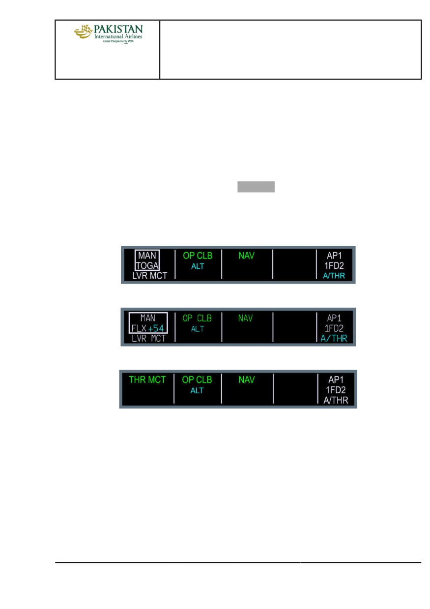
When the speed trend arrow reaches the Green Dot speed, pull the ALT knob to engage OP
CLB. Set the thrust levers to MCT when the LVR MCT message flashes on the FMA (this
message appears, when the speed index reaches Green Dot). Resume the climb phase with
THR MCT. If the thrust levers are already in the FLX/MCT detent, move the thrust levers to CL
and then back to MCT.
FMA MAN TOGA
FMA MAN FLEX
FMA THR MCT
If the engine failure occurs after takeoff, the noise abatement procedures are no longer a
requirement. In addition, the acceleration altitude provides a compromise between the obstacle
clearance and the engine thrust limiting time. It enables the aircraft to fly with Flap 0 and at
Green Dot speed that provides the best climb gradient.
When the aircraft is established on the final takeoff flight path, the flight crew should continue
the ECAM procedure until the STATUS page appears.
At this point, the flight crew should:
- Ensure that the Acceleration flow pattern is performed
- Consider to relight the engine (if no damage).
Then, the flight crew should review the STATUS page.
PIA A318/A319/A320/A321 FLEET
PR-AEP-ENG P 15/26
FCTM
← E →
12 JAN 22
PROCEDURES
ABNORMAL AND EMERGENCY PROCEDURES
A318/A319/A320/A321
FLIGHT CREW
ENG
TECHNIQUES MANUAL
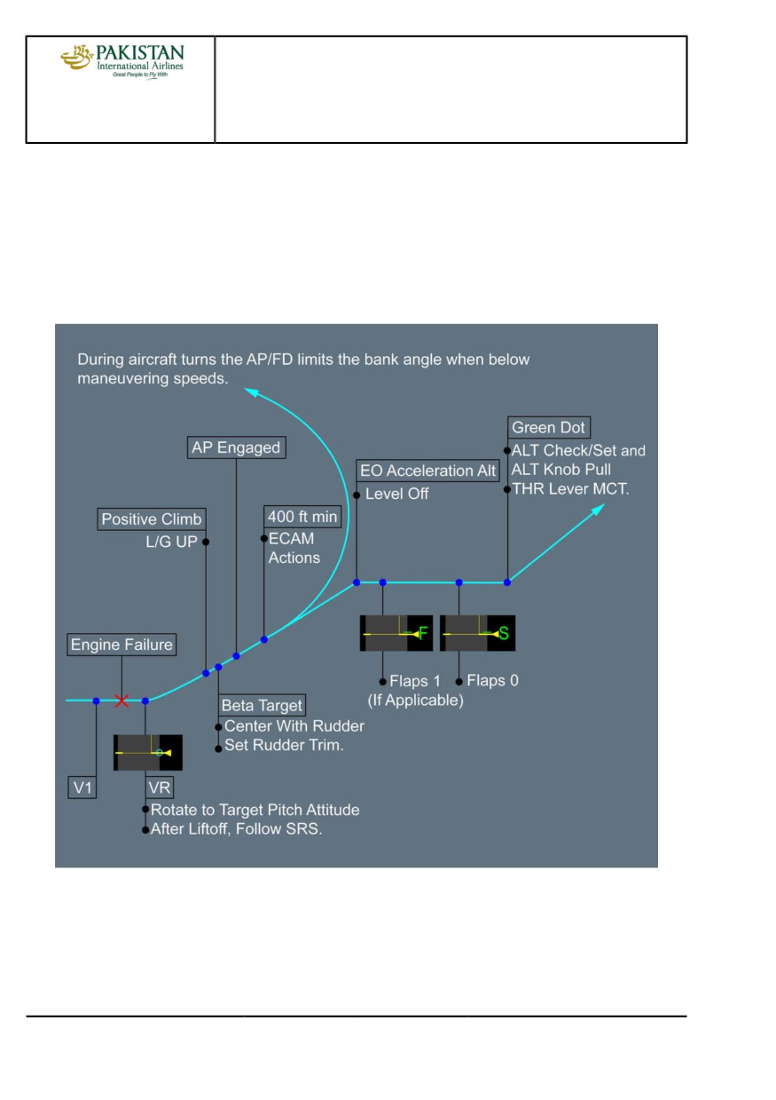
ONE ENGINE OUT FLIGHT PATH
The flight crew flies the one engine-out flight path in accordance with the departure briefing
performed at the gate:
- The EOSID, or
- The SID, or
- Radar vectors, etc.
Takeoff Pattern
PIA A318/A319/A320/A321 FLEET
PR-AEP-ENG P 16/26
FCTM
← E
12 JAN 22
PROCEDURES
ABNORMAL AND EMERGENCY PROCEDURES
A318/A319/A320/A321
FLIGHT CREW
ENG
TECHNIQUES MANUAL
ENGINE FAILURE DURING INITIAL CLIMB
Ident.: PR-AEP-ENG-00018097.0001001 / 20 MAR 17
Applicable to: ALL
This procedure is similar to the "Engine Failure after V1" procedure. If the failure occurs above V2
however, maintain the SRS commanded attitude. In any case, the minimum speed must be V2.
When an engine failure is detected, the FMGS produces predictions based on the engine-out
configuration and any pre-selected speeds entered in the MCDU are deleted.
ENGINE FAILURE DURING CRUISE
Ident.: PR-AEP-ENG-00018098.0001001 / 15 NOV 21
Applicable to: ALL
GENERAL
When an engine failure occurs during cruise, three possible strategies apply:
- The standard strategy
- The obstacle strategy
- The fixed speed strategy.
Unless a specific procedure has been established before dispatch (considering ETOPS or
mountainous areas), the standard strategy is used.
Note:
Pressing the EO CLR key on the MCDU restores the all engine operative predictions and
performance. Reverting to one engine-out performance again is not possible.
PROCEDURE
As soon as the engine failure is recognized, the PF simultaneously:
- Sets all thrust levers to MCT
- Disconnects A/THR.
In cruise, the PF:
- Sets a HDG as appropriate and pulls
- Determines the engine out recovery altitude.
When ready for descent, the PF:
- Sets the SPEED and pulls
- Sets the engine out recovery altitude and pulls to engage for OPEN DES.
When appropriate, the PF requires the ECAM/OEB actions.
At high flight levels, close to the weight limits, the aircraft speed quickly reduces. Thus, the flight
crew should not delay to descent. The crew must not decelerate below green dot.
PIA A318/A319/A320/A321 FLEET
PR-AEP-ENG P 17/26
FCTM
F to G →
12 JAN 22
PROCEDURES
ABNORMAL AND EMERGENCY PROCEDURES
A318/A319/A320/A321
FLIGHT CREW
ENG
TECHNIQUES MANUAL
The A/THR is disconnected to avoid any engine thrust reduction when selecting speed according
to strategy or when pulling for OPEN DES to initiate the descent. With the A/THR disconnected,
the target speed is controlled by the elevator when in OPEN DES.
Carrying out the ECAM actions should not be hurried, as it is important to complete the drill
correctly.
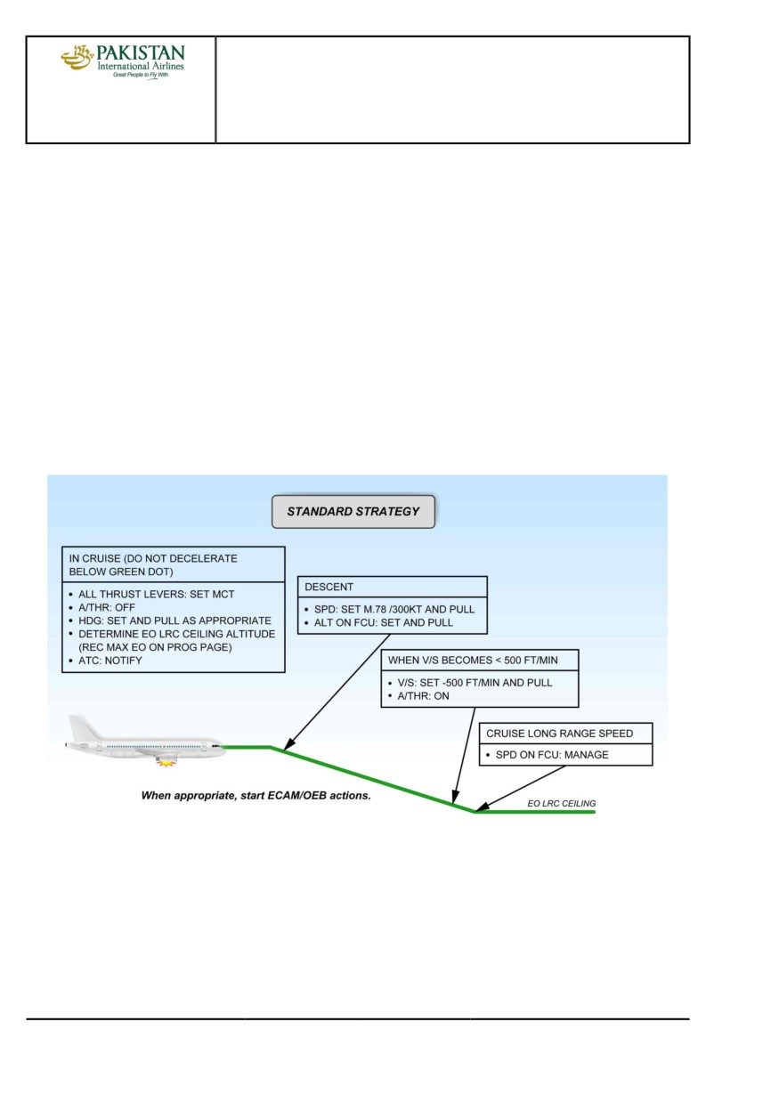
STANDARD STRATEGY
Set speed target M 0.78/300 kt. The speed of 0.78/300 kt is chosen to ensure the aircraft is within
the stabilized windmill engine relight in-flight envelope.
The REC MAX EO Cruise altitude, which equates to LRC Engine-Out maximum FL with anti-icing
off, is displayed on the MCDU PROG page (One engine out gross ceiling at long-range speed is
also available in the performance application of the EFB in case of double FM failure).
When the V/S becomes less than 500 ft/min, select V/S -500 ft/min and A/THR on. Once
established at level off altitude, long-range cruise performance with one engine out may be
computed with the performance application of the EFB.
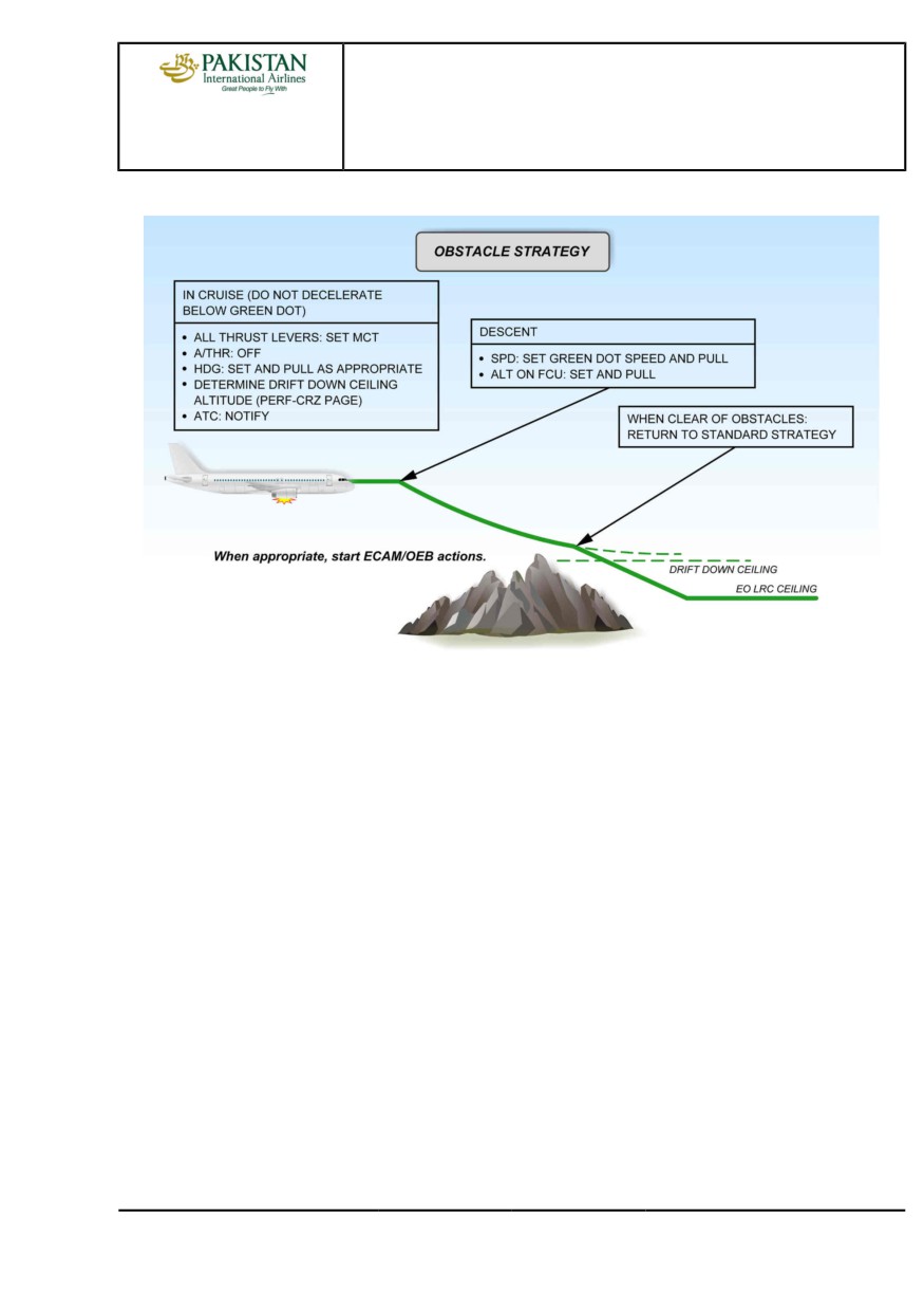
OBSTACLE STRATEGY
To maintain the highest possible level due to terrain, the drift down procedure must be adopted.
The speed target in this case is green dot. The procedure is similar to the standard strategy, but as
the speed target is now green dot, the rate and angle of descent are reduced.
The MCDU PERF CRZ page in EO condition displays the drift down ceiling (One engine out gross
ceiling at green dot speed is also available in the performance application of the EFB).
PIA A318/A319/A320/A321 FLEET
PR-AEP-ENG P 18/26
FCTM
← G →
12 JAN 22
PROCEDURES
ABNORMAL AND EMERGENCY PROCEDURES
A318/A319/A320/A321
FLIGHT CREW
ENG
TECHNIQUES MANUAL
When clear of obstacles, revert to Standard Strategy.
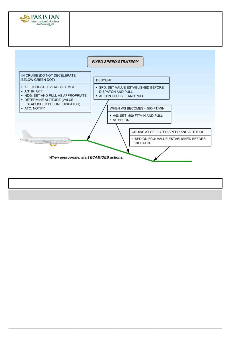
FIXED SPEED STRATEGY
This section provides the fixed speed strategy recommended for ETOPS operation. Refer to
FCOM/PRO-SPO-40-40 Diversion Decision Making.
PIA A318/A319/A320/A321 FLEET
PR-AEP-ENG P 19/26
FCTM
← G →
12 JAN 22
PROCEDURES
ABNORMAL AND EMERGENCY PROCEDURES
A318/A319/A320/A321
FLIGHT CREW
ENG
TECHNIQUES MANUAL
ENGINE STALL
Ident.: PR-AEP-ENG-00018099.0001001 / 28 MAY 20
Applicable to: ALL
An engine stall is the disruption of the airflow in a turbine engine. When the blades of the engine
compressors stall, they are no longer able to compress the air from the front to the rear of the engine.
In some cases, there may be a breakdown of the airflow, with the high pressure air at the end of the
compressor reversing flow, and exiting from the front of the engine. If this occurs, it may result in an
immediate and significant loss of thrust.
From the flight crew perspective, the engine stall is one of the most startling events at takeoff or
during flight. The engine stall should not take the flight crew away from their primary task that is to fly
the aircraft.
An engine stall can be due to any of the following reasons:
- An engine degradation (e.g. compressor blade rupture, or high wear)
- Ingestion of foreign objects (e.g. birds), or ice
- A malfunction of the bleed system
- A malfunction of the engine controls (e.g. fuel scheduling, or stall protection devices)
- A significant disturbance of the airflow (e.g. due to wake turbulence, non-appropriate use of the
thrust reverser after landing, or lightning strike).
PIA A318/A319/A320/A321 FLEET
PR-AEP-ENG P 20/26
FCTM
← G to H →
12 JAN 22
PROCEDURES
ABNORMAL AND EMERGENCY PROCEDURES
A318/A319/A320/A321
FLIGHT CREW
ENG
TECHNIQUES MANUAL
During takeoff, and at high power settings, the symptoms of an engine stall are the following:
- One or more very loud bangs, usually compared to a shotgun being fired a few meters away
- An instant loss of thrust, or even a reverse thrust, that causes a yaw movement
- Fluctuations of the engine parameters (EPR/N1, N2, or N3 ). The engine may give the
impression to pump
- An increase of the EGT
- Engine vibrations
- Flames may be visible from both ends of the engine (inlet / tail pipe)
- Acrid smell in the cockpit.
During cruise, and at low power settings (e.g. at thrust reduction at the T/D), the symptoms of an
engine stall are the following:
- One or more muffled bangs
- Slow or no thrust lever response
- Fluctuations of the engine parameters (EPR/N1, N2, or N3 ). The engine may give the
impression to pump
- An increase of the EGT
- Engine vibrations
- Acrid smell in the cockpit.
Most of the FADECs have functions that:
- Regulate the airflow through the compressor, to prevent engine stalls
- Are able to detect engine stalls
- Try to recover from an engine stall, without flight crew action, by modifying the airflow.
When the FADEC detects an engine stall, the FADEC requests that the ENG 1(2) STALL ECAM alert
is triggered.
The FADEC is not able to detect an engine stall in all cases. Therefore, if the flight crew detects one
or a combination of the engine stall symptoms, the flight crew should suspect an engine stall, and
apply the QRH Engine Stall procedure.
The Engine Stall procedure is not a memory item. Therefore, if a stall occurs during the cruise phase,
the flight crew shall take the time to assess the situation before applying the procedure, as most of
the times the FADEC will self-recover from the stall before any flight crew action. The Engine Stall
procedure (ECAM or QRH) is as follows:
- When the flight crew has stabilized the aircraft trajectory, the flight crew first reduces thrust to idle
on the affected engine.
This action reduces the differential pressure across the compressor. This helps the engine airflow
to become more stable.
- When at idle thrust, the flight crew checks the stability of the engine parameters on the EWD,
and particularly the EPR/N1, EGT, N2, and N3 . The flight crew should also check the engine
vibrations on the ENG SD page.
PIA A318/A319/A320/A321 FLEET
PR-AEP-ENG P 21/26
FCTM
← H →
12 JAN 22
PROCEDURES
ABNORMAL AND EMERGENCY PROCEDURES
A318/A319/A320/A321
FLIGHT CREW
ENG
TECHNIQUES MANUAL
- The flight crew shuts down the engine if:
• The fluctuations of the engine parameters, or the high EGT, or the engine vibrations persist, or
• The symptoms of the engine stall persist at idle thrust.
- If the engine parameters are normal:
• The flight crew selects the anti-ice on, in order to increase the bleed demand.
This reduces the pressure at the exit of the compressor, and helps the airflow to circulate in the
engine turbine from front to rear.
• Then, the flight crew slowly advances the thrust levers, as long as the engine stall does not
occur again. The engine response may be slow at high altitude.
▪ If the engine stall reoccurs, the flight crew keeps the engine thrust below the stall threshold.
The flight crew should not shut down the engine if the engine stall can be avoided. The flight
crew should manually control the thrust on the affected engine between idle and the identified
stall threshold for the remainder of the flight.
▪ If the engine stall does not reoccur, the flight crew can resume normal operation of the
engine.
The flight crew must report any engine stall for maintenance action.
ENGINE TAILPIPE FIRE
Ident.: PR-AEP-ENG-00018100.0001001 / 20 MAR 17
Applicable to: ALL
An engine tailpipe fire can only occur at engine start or at engine shutdown. It is the result of an
excess of fuel in the combustion chamber, in the turbine or in the exhaust nozzle, that ignites. A
tailpipe fire is an internal fire in the engine, compared with an engine fire that occurs outside the
engine core and gas path. No critical areas are affected in the engine in the case of a tailpipe fire.
However, it can have an effect on the aircraft (e.g. damage the flaps). The correct method to manage
an engine tailpipe fire is to stop the fuel flow, and to ventilate the engine.
In the case of a tailpipe fire, there is no cockpit alert. The only indication can be an increasing EGT
due to the fire in the turbine. Therefore, most of the time, the ground crew, cabin crew, or ATC
visually detect the tailpipe fire.
In the case of a tailpipe fire, the flight crew must apply the QRH ENG TAILPIPE FIRE procedure,
which requires the flight crew to:
- Shut down the engine, in order to stop the fuel flow
- Dry crank the engine, to remove the remaining fuel.
The flight crew should not use the ENG FIRE pb. This cuts off the electrical supply of the FADEC,
and stops the dry crank sequence performed by the FADEC.
The flight crew should not use the fire extinguisher, as it does not extinguish an internal engine fire.
As a first priority, the fuel flow must be stopped, and the engine must be ventilated.
PIA A318/A319/A320/A321 FLEET
PR-AEP-ENG P 22/26
FCTM
← H to I →
12 JAN 22
PROCEDURES
ABNORMAL AND EMERGENCY PROCEDURES
A318/A319/A320/A321
FLIGHT CREW
ENG
TECHNIQUES MANUAL
If the tailpipe fire procedure does not stop the fire, or if bleed air is not easily available, the ground
crew can use a ground fire extinguisher as a last option. Ground fire extinguishing agent can cause
serious corrosive damage to the engine and requires a maintenance action on the engine.
ENGINE VIBRATIONS
Ident.: PR-AEP-ENG-00018101.0001001 / 20 MAR 17
Applicable to: ALL
Engine vibrations are usually caused by an imbalance of the engine that can be due to many reasons
such as:
- A deformation of one or several blades due to Foreign Object Damage (FOD), or a bird strike
- A rupture or a loss of one or several blades
- An internal engine failure (e.g. engine stall)
- A fan icing
High engine vibration alone does not require an engine in-flight shutdown. If the engine needs to be
shutdown, other symptoms and certainly an ECAM alert will warn the flight crew, and request them to
shut down the engine.
A high N1 vibration level may be accompanied by perceivable airframe vibrations.
When the vibration level exceeds a certain threshold, the ECAM advisory function automatically
highlights the affected parameter. When the flight crew identifies high engine vibrations, the flight
crew must refer to the ECAM ADVISORY CONDITIONS section of the QRH. This section guides the
flight crew to the QRH HIGH ENGINE VIBRATION procedure.
On the A320neo, the ECAM advisory is replaced by an ECAM alert that guides the flight crew toward
the QRH HIGH ENGINE VIBRATION procedure.
In the case of high engine vibrations, the flight crew first checks the engine parameters, and
crosschecks them with the other engine. The flight crew identifies if there are engine vibrations only,
or if there is another problem on the engine for which the flight crew may expect an ECAM alert.
Then the flight crew determines if icing is suspected or not. The flight crew should suspect icing if N1
vibrations occur without variation on other engine parameters. If the flight crew notices unexpected
behavior on other engine parameters, the flight crew should consider that icing is not suspected.
These checks take into account the cases of engine problems in icing conditions, and also the cases
of vibrations due to icing, out of standard icing conditions.
If the flight crew suspects icing, and if flight conditions permit, the flight crew should shed the ice with
the following procedure:
- The flight crew disconnects the A/THR
- The flight crew performs several large thrust variations from idle to a thrust compatible with the
flight phase.
It may be necessary to perform several engine run-ups (decrease and then increase of thrust) to
fully shed the ice.
PIA A318/A319/A320/A321 FLEET
PR-AEP-ENG P 23/26
FCTM
← I to J →
12 JAN 22
PROCEDURES
ABNORMAL AND EMERGENCY PROCEDURES
A318/A319/A320/A321
FLIGHT CREW
ENG
TECHNIQUES MANUAL
If the flight crew does not suspect icing, and if flight conditions permit, the flight crew reduces thrust
to make the vibrations decrease, and stay below the advisory threshold.
If the vibrations do not decrease, there may be another problem with the engine. The flight crew
should expect an ECAM alert that will provide guidance on the actions to perform.
Finally, during the taxi-in phase, the flight crew may consider to shut down the engine if the flight
crew experienced vibrations in flight, or if the flight crew experiences vibrations during taxi. On
ground, the flight crew should consider engine shutdown in order to avoid increased damage to the
engine.
ONE ENGINE INOPERATIVE - CIRCLING
Ident.: PR-AEP-ENG-00018102.0001001 / 20 MAR 17
Applicable to: ALL
In normal conditions, circling with one engine inoperative requires the down wind leg to be flown in
CONF 3, with landing gear extended.
In hot and high conditions and at high landing weight, the aircraft may not be able to maintain level
flight in CONF 3 with landing gear down. The flight crew should check the maximum weight showed
in the QRH CIRCLING APPROACH WITH ONE ENGINE INOPERATIVE procedure table. If the
landing weight is above this maximum value, the landing gear extension should be delayed until
established on final approach.
If the approach is flown at less than 750 ft RA, the warning "L/G NOT DOWN" will be triggered.
"TOO LOW GEAR" warning is to be expected, if the landing gear is not downlocked at 500 ft RA.
Therefore, if weather conditions permit, it is recommended to fly a higher circling pattern.
ONE ENGINE INOPERATIVE - GO-AROUND
Ident.: PR-AEP-ENG-00018103.0001001 / 20 MAR 17
Applicable to: ALL
A one engine inoperative go-around is similar to a go-around flown with all engines.
On the application of TOGA, the flight crew must apply rudder promptly to compensate for the
increase in thrust and consequently to keep the beta target centred.
Provided the flap lever is selected to Flap 1 or greater, SRS will engage and will be followed. If SRS
is not available, the initial target pitch attitude will be 12.5 °.
The lateral FD mode will be GA TRK (or NAV if option installed) and this must be considered with
respect to terrain clearance.
At the engine-out acceleration altitude, apply the same technique as described earlier. Refer to
PR-AEP-ENG Engine Failure after V1.
PIA A318/A319/A320/A321 FLEET
PR-AEP-ENG P 24/26
FCTM
← J to L
12 JAN 22
PROCEDURES
ABNORMAL AND EMERGENCY PROCEDURES
A318/A319/A320/A321
FLIGHT CREW
ENG
TECHNIQUES MANUAL
ONE ENGINE INOPERATIVE - LANDING
Ident.: PR-AEP-ENG-00018104.0001001 / 19 APR 17
Applicable to: ALL
Autoland is available with one engine inoperative, and maximum use of the AP should be made to
minimise crew workload. If required, a manual approach and landing with one engine inoperative is
conventional. The flight crew should trim to keep the slip indication centred. It remains yellow as long
as the thrust on the remaining engine(s) is below a certain value.
With flap selected and above this threshold value, the indicator becomes the blue beta target. This is
a visual cue that the aircraft is approaching its maximum thrust capability.
The flight crew should not select the gear down too early, as large amounts of power will be required
to maintain level flight at high weights and/or high altitude airports.
The flight crew can reset the rudder trim in the later phase of the approach, before engine thrust
reduction. On pressing the rudder trim reset button, the trim is removed and the flight crew should
anticipate the increased rudder force required. With rudder trim at zero, the neutral rudder pedal
position corresponds to zero rudder and zero nose wheel deflection.
THRUST LEVERS MANAGEMENT IN THE CASE OF INOPERATIVE REVERSER(S)
Ident.: PR-AEP-ENG-00018106.0001001 / 20 MAR 17
Applicable to: ALL
PREFACE
This section provides recommendations on thrust levers management in case of inoperative
reverser(s). These recommendations are applicable in case of in-flight failure (including engine
failure) and/or in case of MEL dispatch with reverser(s) deactivated.
AT LEAST ONE REVERSER OPERATIVE
If at least one reverser is operative, the general recommendation is to select the reverser thrust on
both engines during rejected takeoff (RTO) and at landing, as per normal procedures.
Note:
The ENG 1(2) REVERSER FAULT ECAM caution may be triggered after the reverser
thrust is selected. This is to remind the flight crew that one reverser is inoperative.
NO REVERSERS OPERATIVE
If no reversers are operative, the general recommendation is to not select the reverser thrust
during RTO and at landing.
However, the PF still sets both thrust levers to the IDLE detent, as per normal procedures.
PIA A318/A319/A320/A321 FLEET
PR-AEP-ENG P 25/26
FCTM
M to N →
12 JAN 22
PROCEDURES
ABNORMAL AND EMERGENCY PROCEDURES
A318/A319/A320/A321
FLIGHT CREW
ENG
TECHNIQUES MANUAL
BRIEFING
IMPORTANCE OF THE FLIGHT CREW BRIEFING
Among others, the aircraft status must be reviewed during the flight crew briefing. Any
particularities (operational consequences, procedures, associated task sharing and callout)
must be reviewed at that time. The flight crew must notably review:
- The status of the thrust reversers and if reverser thrust can be used
- Operational effect (aircraft handling during roll-out).
PIA A318/A319/A320/A321 FLEET
PR-AEP-ENG P 26/26
FCTM
← N
12 JAN 22
PROCEDURES
ABNORMAL AND EMERGENCY PROCEDURES
A318/A319/A320/A321
FLIGHT CREW
F/CTL
TECHNIQUES MANUAL
ABNORMAL FLAPS/SLATS CONFIGURATION
Ident.: PR-AEP-F_CTL-00019291.0001001 / 12 NOV 20
Applicable to: ALL
CAUSES
Abnormal operation of the flaps and/or slats may be due to one of the following problems:
- Double SFCC failure
- Double hydraulic failure (B+G or Y+G)
- Flaps/Slats jammed (operation of the WTB)
CONSEQUENCES
Abnormal operation of the flaps and slats has significant consequences since:
- The control laws may change
- The selected speed must be used
- An early stabilized approach should be preferred
- The approach attitudes change
- Approach speeds and landing distances increase
- The go-around procedure may have to be modified.
Note:
The FMS predictions do not take into account the slat or flap failures. Since fuel
consumption is increased, these predictions are not valid.
FAILURE AT TAKEOFF
Should a flap/slat retraction problem occur at takeoff, the crew will PULL the speed knob for
selected speed to stop the acceleration and avoid exceeding VFE. The overspeed warning is
computed according to the actual slats/flaps position.
The landing distance available at the departure airport and the aircraft gross weight will determine
the crew's next course of action.
FAILURE DURING THE APPROACH
The detection of a slat or flap failure occurs with the selection of flap lever during the approach.
With A/THR operative, the managed speed target will become the next manoeuvring characteristic
speed e.g. S speed when selecting flap lever to 1. At this stage, if a slat or flap failure occurs, the
crew will:
- Pull the speed knob for selected speed to avoid further deceleration
- Delay the approach to complete the ECAM procedure
- Refer to LANDING WITH FLAPS OR SLATS JAMMED QRH procedure.
- Update the approach briefing.
In the QRH, the line, "SPD SEL
VFE NEXT -5 kt" is designed to allow the crew to configure
the aircraft for landing whilst controlling the speed in a safe manner. This procedure may involve
PIA A318/A319/A320/A321 FLEET
PR-AEP-F_CTL P 1/2
FCTM
A →
10 AUG 21
PROCEDURES
ABNORMAL AND EMERGENCY PROCEDURES
A318/A319/A320/A321
FLIGHT CREW
F/CTL
TECHNIQUES MANUAL
reducing speed below the manoeuvring speed for the current configuration which is acceptable
provided the speed is kept above VLS. The speed reduction and configuration changes should
preferably be carried out wings level.
Assuming VLS is displayed on the PFD, VAPP should be close to VLS + wind correction, since
this speed is computed on the actual slat/flap position.
The AP may be used down to 500 ft AGL. As the AP is not tuned for the abnormal configurations,
its behavior can be less than optimum and must be monitored.
During the approach briefing, emphasis should be made of:
- Tail strike awareness
- The go-around configuration
- Any deviation from standard call out
- The speeds to be flown, following a missed approach
- At the acceleration altitude, selected speed must be used to control the acceleration to the
required speed for the configuration.
Consider the fuel available and the increased consumption associated with a diversion when
flying with flaps and/or slats jammed. Additionally, when diverting with flaps/slats extended, cruise
altitude is limited to 20 000 ft.
PIA A318/A319/A320/A321 FLEET
PR-AEP-F_CTL P 2/2
FCTM
← A
10 AUG 21
PROCEDURES
ABNORMAL AND EMERGENCY PROCEDURES
A318/A319/A320/A321
FLIGHT CREW
FUEL
TECHNIQUES MANUAL
FUEL LEAK
Ident.: PR-AEP-FUEL-00019292.0001001 / 09 NOV 20
Applicable to: ALL
Significant fuel leaks, although rare, are sometimes difficult to detect.
Fuel check will be carried out by:
- Checking that the remaining fuel added to the burnt fuel corresponds to the fuel on board at the
gate
- Maintaining the fuel log and comparing the fuel on board to the expected flight plan fuel.
Fuel checks should be carried out when overflying a waypoint or at least every 30 min. Any
discrepancy should alert the crew and investigation should be carried out without delay.
In addition, the flight crew can also suspect a fuel leak if:
General indications
- The sum of FOB and FU is significantly less than FOB at engine start, or is decreasing
- There is a discrepancy between the fuel on board and the expected flight plan fuel
- The total fuel quantity abnormally decreases
- A fuel imbalance develops
- Fuel is smelt in the cabin
- The destination EFOB is decreasing or is displayed amber on the FMS F-PLN page
Specific to a hole in a tank
- The fuel quantity of one wing decreases abnormally fast
- A passenger or Cabin Crew observes a fuel spray from a wing
Specific to an engine fuel leak
- The fuel flow is excessive, or the N1 indication decreases
- The fuel quantity of one wing tank decreases abnormally fast
- A passenger or Cabin Crew observes a fuel spray from an engine/pylon
Specific to a pipe rupture in a tank
- A tank overflows.
Any time an unexpected fuel quantity indication, an ECAM fuel message or an imbalance is
noted, a fuel leak should be considered as a possible cause. Initial indications should be carefully
cross-checked by reference to other means, including if possible, a visual inspection.
If a fuel leak is suspected, the flight crew should perform the [QRH] FUEL LEAK procedure.
The main steps of the [QRH] FUEL LEAK procedure are:
If the fuel leak is confirmed coming from the engine/pylon:
The affected engine is shut down to isolate the fuel leak and the fuel cross-feed valve may be
used as required.
PIA A318/A319/A320/A321 FLEET
PR-AEP-FUEL P 1/2
FCTM
A →
10 AUG 21
PROCEDURES
ABNORMAL AND EMERGENCY PROCEDURES
A318/A319/A320/A321
FLIGHT CREW
FUEL
TECHNIQUES MANUAL
If the fuel leak is not confirmed coming from the engine/pylon or if the leak is not located:
- Isolate each tank: Maintain the cross-feed valve closed and switch off the center pumps. Each
wing tank feeds the associated engine.
- If the fuel quantity decreases faster in one wing tank than in the other wing tank, the fuel leak
is identified as coming from one wing tank. In this case, the associated engine is shut down in
order to confirm if the leak comes from the wing tank or from the engine.
- If the fuel quantity symmetrically decreases in both wing tanks and the fuel quantity in the
center tank decreases, the fuel leak comes from the center tank or the APU feed line.
FUEL OVERREAD
Ident.: PR-AEP-FUEL-00024326.0001001 / 09 NOV 20
Applicable to: ALL
Fuel check will be carried out by:
- Checking that the remaining fuel added to the burnt fuel corresponds to the fuel on board at the
gate
- Maintaining the fuel log and comparing the fuel on board to the expected flight plan fuel.
Fuel checks should be carried out when overflying a waypoint or at least every 30 min. Any
discrepancy should alert the crew and investigation should be carried out.
The flight crew can suspect a fuel overread if:
- The sum of FOB and FU is significantly more than FOB at engine start, or is increasing
- There is an abnormal discrepancy between the fuel on board and the expected flight plan fuel
- The total fuel quantity abnormally increases
- The destination EFOB abnormally increases.
Depending on the FWC standard, the FUEL F.USED/FOB DISAGREE alert may address both cases
of fuel leak and fuel overread.
If the flight crew detects a fuel overread, or if the FUEL F.USED/FOB DISAGREE alert triggers to
indicate a fuel overread, fuel management is affected. The flight crew should apply the [QRH] FUEL
OVERREAD procedure (Refer to FCOM/PRO-ABN-FUEL [QRH] FUEL OVERREAD).
The flight crew should be aware that, for the remainder of the flight:
- The FMS predictions are no longer reliable
- The fuel low level ECAM alerts are still valid. These alerts are triggered by sensors that are
independent from the fuel quantity indications.
- The remaining FOB shall be computed from data that the flight crew considers as still valid. It may
be fuel used, flight plan FOB, FOB at engine start.
- The unusual discrepancy shall be recorded in the aircraft logbook and maintenance action is due
before the next flight.
PIA A318/A319/A320/A321 FLEET
PR-AEP-FUEL P 2/2
FCTM
← A to B
10 AUG 21
PROCEDURES
ABNORMAL AND EMERGENCY PROCEDURES
A318/A319/A320/A321
FLIGHT CREW
HYD
TECHNIQUES MANUAL
HYDRAULIC GENERATION PARTICULARITIES
Ident.: PR-AEP-HYD-00019294.0001001 / 25 JUL 17
Applicable to: ALL
PREFACE
The aircraft has three continuously operating hydraulic systems: green, blue and yellow. A
bidirectional Power Transfer Unit (PTU) enables the yellow system to pressurize the green system
and vice versa. Hydraulic fluid cannot be transferred from one system to another.
PTU PRINCIPLE
In flight, the PTU operates automatically if differential pressure between green and yellow systems
exceeds 500 PSI. This allows to cover the loss of one engine or one engine driven pump cases.
USE OF PTU IN CASE OF FAILURE
In case of reservoir low level, reservoir overheat, reservoir low air pressure, the PTU must be
switched OFF as required by ECAM to avoid a PTU overheat which may occur two minutes later.
Indeed, a PTU overheat may lead to the loss of the second hydraulic circuit.
RECOMMENDATIONS
When required by the ECAM, the PTU should be switched off without delay in case of:
- HYD G(Y) RSVR LO LVL
- HYD G(Y) RSVR LO AIR PR (Only if pressure fluctuates)
- HYD G(Y) RSVR OVHT
DUAL HYDRAULIC FAILURES
Ident.: PR-AEP-HYD-00019295.0001001 / 12 NOV 20
Applicable to: ALL
PREFACE
Single hydraulic failures have very little effect on the handling of the aircraft but will cause a
degradation of the landing capability to CAT 3 SINGLE.
Dual hydraulic failures however, although unlikely, are significant due to the following
consequences depending on the affected hydraulic circuits (Refer to PR-AEP-HYD Remaining
Systems):
- Loss of AP
- Flight control law degradation
- Landing in abnormal configuration
- Extensive ECAM procedures with associated workload and task-sharing considerations
- Significant considerations for approach and landing.
PIA A318/A319/A320/A321 FLEET
PR-AEP-HYD P 1/6
FCTM
A to B →
10 AUG 21
PROCEDURES
ABNORMAL AND EMERGENCY PROCEDURES
A318/A319/A320/A321
FLIGHT CREW
HYD
TECHNIQUES MANUAL
GENERAL GUIDELINES
It is important to note that the AP will not be available to the crew but both FD and A/THR still
remain. Additionally, depending on the affected hydraulic circuits, aircraft handling characteristics
may be different due to the loss of some control surfaces. The PF will maneuver with care to avoid
high hydraulic demand on the remaining systems.
The PF will be very busy flying the aircraft and handling the communications with the flight controls
in Alternate Law (HYD G+B SYS LO PR or HYD G+Y SYS LO PR).
A double hydraulic failure is an emergency situation, with red LAND ASAP displayed, and a
MAYDAY should be declared to ATC. A landing must be carried out as soon as possible bearing in
mind, however, that the ECAM actions should be completed prior the approach.
PF will then require the ECAM actions. A clear reading of STATUS is essential to assess the
aircraft status and properly sequence actions during the approach.
This failure is called a "complex procedure" and the QRH summary should be referred to upon
completion of the ECAM procedure (Refer to AOP-30-60 Use of Summaries).
While there is no need to remember the following details, an understanding of the structure of
the hydraulic and flight control systems would be an advantage. The F/CTL SD page and the
OPS DATA section of the QRH provide an overview of the flight controls affected by the loss of
hydraulic systems.
The briefing will concentrate on safety issues since this will be a hand-flown approach with certain
handling restrictions:
- Use of the selected speeds on the FCU
- Landing gear gravity extension
- Approach configuration and flap lever position
- Approach speed VAPP
- An early stabilized approach will be preferred
- Tail strike awareness
- Braking and steering considerations
- Go around call out, aircraft configuration and speed.
The STATUS page requires, in each case, a landing gear gravity extension. The LANDING GEAR
GRAVITY EXTENSION procedure will be completed with reference to the QRH.
PIA A318/A319/A320/A321 FLEET
PR-AEP-HYD P 2/6
FCTM
← B
10 AUG 21

PROCEDURES
ABNORMAL AND EMERGENCY PROCEDURES
A318/A319/A320/A321
FLIGHT CREW
HYD
TECHNIQUES MANUAL
REMAINING SYSTEMS
Ident.: PR-AEP-HYD-00019296.0001001 / 25 JUL 17
Criteria: SA
Applicable to: MSN 02155-02274
Remaining systems
Flight phase
Systems
HYD G+B SYS LO PR
HYD G+Y SYS LO PR
HYD B+Y SYS LO PR
Cruise
Auto pilot
Inop
Inop
Inop
Yaw damper
YD2 only
Inop
YD1 only
Control law
ALTN LAW and DIRECT
ALTN LAW and DIRECT
NORM LAW
LAW when L/G DN
LAW when L/G DN
Stabilizer
Avail
Inop (1)
Avail
Spoilers
2 SPLRS/wing
1 SPLR/wing
2 SPLRS/wing
Elevator
R ELEV only
Avail
L ELEV only
Aileron
Inop
Avail
Avail
(1)
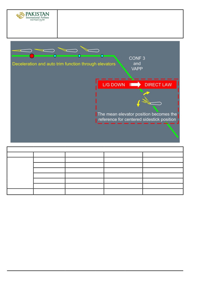
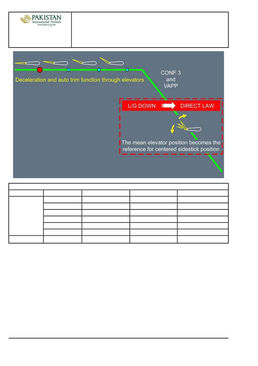
The stabilizer is lost. In alternate law, the auto trim function is provided through the elevators. At
landing gear extension, switching to direct law, the auto trim function is lost. However, the mean
elevator position at that time is memorized, and becomes the reference for centered sidestick
position. This is why, in order to ensure proper centered sidestick position for approach and
landing, the procedure requires to wait for stabilization at VAPP, before landing gear extension.
If this procedure is missed, the flare and pitch control in case of go-around may be difficult.
The PFD message USE MAN PITCH TRIM after landing gear extension should thus be
disregarded.
PIA A318/A319/A320/A321 FLEET
PR-AEP-HYD P 3/6
FCTM
C →
10 AUG 21
PROCEDURES
ABNORMAL AND EMERGENCY PROCEDURES
A318/A319/A320/A321
FLIGHT CREW
HYD
TECHNIQUES MANUAL
Remaining systems
Flight phase
Systems
HYD G+B SYS LO PR
HYD G+Y SYS LO PR
HYD B+Y SYS LO PR
Landing
Slats/Flaps
FLAPS slow only
SLATS slow only (1)
SLATS/FLAPS slow
L/G extension
Gravity
Gravity
Gravity
Braking
ALTN BRK only
Y ACCU PRESS only
NORM BRK only
Anti skid
Avail
Inop
Avail
Nose wheel steering
Inop
Inop
Inop
Reverse
REV 2 only
Inop
REV 1 only
Go/around
L/G retraction
Inop
Inop
Inop
(1)
High pitch during approach should be expected. Approach briefing should outline it for tail strike
awareness and pitch attitude will be monitored during flare.
PIA A318/A319/A320/A321 FLEET
PR-AEP-HYD P 4/6
FCTM
← C →
10 AUG 21

PROCEDURES
ABNORMAL AND EMERGENCY PROCEDURES
A318/A319/A320/A321
FLIGHT CREW
HYD
TECHNIQUES MANUAL
REMAINING SYSTEMS
Ident.: PR-AEP-HYD-00019296.0002001 / 25 JUL 17
Criteria: P4576, SA
1 Applicable to: MSN 02719-07792
Remaining systems
Flight phase
Systems
HYD G+B SYS LO PR
HYD G+Y SYS LO PR
HYD B+Y SYS LO PR
Cruise
Auto pilot
Inop
Inop
Inop
Yaw damper
YD2 only
Inop
YD1 only
Control law
ALTN LAW and DIRECT
ALTN LAW and DIRECT
NORM LAW
LAW when L/G DN
LAW when L/G DN
Stabilizer
Avail
Inop (1)
Avail
Spoilers
2 SPLRS/wing
1 SPLR/wing
2 SPLRS/wing
Elevator
R ELEV only
Avail
L ELEV only
Aileron
Inop
Avail
Avail
(1)
The stabilizer is lost. In alternate law, the auto trim function is provided through the elevators. At
landing gear extension, switching to direct law, the auto trim function is lost. However, the mean
elevator position at that time is memorized, and becomes the reference for centered sidestick
position. This is why, in order to ensure proper centered sidestick position for approach and
landing, the procedure requires to wait for stabilization at VAPP, before landing gear extension.
If this procedure is missed, the flare and pitch control in case of go-around may be difficult.
The PFD message USE MAN PITCH TRIM after landing gear extension should thus be
disregarded.
PIA A318/A319/A320/A321 FLEET
PR-AEP-HYD P 5/6
FCTM
← C →
10 AUG 21
PROCEDURES
ABNORMAL AND EMERGENCY PROCEDURES
A318/A319/A320/A321
FLIGHT CREW
HYD
TECHNIQUES MANUAL
Remaining systems
Flight phase
Systems
HYD G+B SYS LO PR
HYD G+Y SYS LO PR
HYD B+Y SYS LO PR
Landing
Slats/Flaps
FLAPS slow only
SLATS slow only (1)
SLATS/FLAPS slow
L/G extension
Gravity
Gravity
Gravity
Braking
ALTN BRK only
Y ACCU PRESS only
NORM BRK only
Anti skid
Avail
Inop
Avail
Nose wheel steering
Avail
Inop
Inop
Reverse
REV 2 only
Inop
REV 1 only
Go/around
L/G retraction
Inop
Inop
Inop
(1)
High pitch during approach should be expected. Approach briefing should outline it for tail strike
awareness and pitch attitude will be monitored during flare.
PIA A318/A319/A320/A321 FLEET
PR-AEP-HYD P 6/6
FCTM
← C
10 AUG 21
PROCEDURES
ABNORMAL AND EMERGENCY PROCEDURES
A318/A319/A320/A321
FLIGHT CREW
L/G
TECHNIQUES MANUAL
LANDING WITH ABNORMAL L/G
Ident.: PR-AEP-LG-00019297.0001001 / 09 NOV 17
Applicable to: ALL
To avoid unnecessary application of the L/G GRAVITY EXTENSION and the LDG WITH
ABNORMAL L/G QRH procedures, the flight crew must check for the three landing gear green
indications on the ECAM WHEEL SD page: at least one green triangle on each landing gear is
sufficient to indicate that the landing gear is down and locked. The flight crew must also rely also on
the “LDG GEAR DN” green MEMO. This is sufficient to confirm that the landing gear is downlocked.
If one landing gear is not downlocked, the flight crew must perform the LDG WITH ABNORMAL L/G
QRH procedure. In this case, it is always better to land with any available gear rather than carry out a
landing without any gear.
In all cases, weight should be reduced as much as possible to provide the slowest possible
touchdown speed.
A fuel imbalance may be considered by the flight crew. Landing with a lighter wing on the affected
side allows to keep it up longer and delay the moment of nacelle contact. If the imbalance advisory
triggers, the flight crew can disregard it, as the aircraft handling qualities are not significantly affected.
Although foaming of the runway is not a requirement, full advantage should be taken of any ATC
offer to do so.
The passengers and cabin crew should be informed of the situation in good time. This will allow the
cabin crew to prepare the cabin and perform their emergency landing and evacuation procedures.
If one or both main landing gears in abnormal position, the ground spoilers will not be armed to keep
as much roll authority as possible for maintaining the wings level. Ground spoiler extension would
prevent spoilers from acting as roll surfaces.
The flight crew will not arm the autobrake as manual braking will enable better pitch and roll control.
Furthermore, with at least one main landing gear in the abnormal position, the autobrake cannot be
activated (ground spoilers not armed).
With one main landing gear not extended, the reference speed used by the anti-skid system is not
correctly initialized. Consequently, the anti-skid must be switched off to prevent permanent brake
release.
In all cases, a normal approach should be flown and control surfaces used as required to maintain
the aircraft in a normal attitude for as long as possible after touchdown. The engines should be shut
down early enough to ensure that fuel is cut off prior to nacelle touchdown, but late enough to keep
sufficient authority on control surfaces in order to:
- Maintain runway axis
- Prevent nacelle contact on first touch down
- Maintain wing level and pitch attitude as long as possible.
PIA A318/A319/A320/A321 FLEET
PR-AEP-LG P 1/6
FCTM
A →
23 NOV 21
PROCEDURES
ABNORMAL AND EMERGENCY PROCEDURES
A318/A319/A320/A321
FLIGHT CREW
L/G
TECHNIQUES MANUAL
Considering a realistic hydraulic demand, the hydraulic power remains available up to approximately
30 s after the shut down of the related engine. It is the reason why the recommendations to switch
the ENG masters OFF are as follow:
- If NOSE L/G abnormal
Before nose impact
- If one MAIN L/G abnormal
At touch down
- If both MAIN L/G abnormal
In the flare, before touch down
If one main landing gear is in abnormal position, the reversers will not be used to prevent the ground
spoilers extension. If the nose landing gear is in abnormal position, the reversers will not be used to
prevent the nose down effect induced by the reverse thrust.
The engines and APU fire pbs are pushed when the use of flight controls is no longer required i.e.
when aircraft has stopped.
NOSE WHEEL STEERING FAULT
Ident.: PR-AEP-LG-00019298.0001001 / 20 MAR 17
Applicable to: ALL
If the Nose Wheel Steering (NWS) is lost for taxiing, the flight crew can steer the aircraft with
differential braking technique. If the flight crew does not have experience with this technique, he
should preferably request a towing to return to the gate. The flight crew can request the towing early
in approach, if the failure has been triggered in flight.
TAXI WITH DEFLATED OR DAMAGED TIRES
Ident.: PR-AEP-LG-00021646.0001001 / 01 JUN 17
Applicable to: ALL
In some abnormal situations, after a rejected takeoff or after landing, the flight crew may need to
vacate the runway and taxi the aircraft with deflated or damaged tires.
The flight crew must ensure that the number and position of deflated or damaged tires are in
accordance with the limitations provided in the FCOM. Refer to FCOM/LIM-LG Taxi with Deflated or
Damaged Tires.
In order to identify the number and position of the affected tires, the flight crew can use the tire
pressure indication available on the WHEEL SD page.
If the number or position of the affected tires is not in accordance with the limitations provided in the
FCOM, the ground crew must change a sufficient number of wheels before taxi, in order to ensure
compliance with the FCOM limitations.
PIA A318/A319/A320/A321 FLEET
PR-AEP-LG P 2/6
FCTM
← A to C →
23 NOV 21
PROCEDURES
ABNORMAL AND EMERGENCY PROCEDURES
A318/A319/A320/A321
FLIGHT CREW
L/G
TECHNIQUES MANUAL
As indicated in the FCOM limitations, the nosewheel steering angle must be limited to a maximum of
30 °. In order to ensure that this limitation is not exceeded, the flight crew should use the graduations
available on the steering handwheel.
The 30 ° limitation for the nosewheel steering angle corresponds to either of the following:
- A steering handwheel position on the 3rd graduation, or
- A steering handwheel position in the middle of the 2nd and 3rd graduation with pedals fully deflected
in the same direction.
WHEEL TIRE DAMAGE SUSPECTED
Ident.: PR-AEP-LG-00019300.0002001 / 15 NOV 21
Criteria: P4576, SA
1 Applicable to: MSN 02719-07792
GENERAL
The flight crew must apply the WHEEL TIRE DAMAGE SUSPECTED procedure in the case of
suspicion of damage on one or several tires.
The crew may suspect tire damaged based on several indications. This include, but are not limited
to:
- Information from the ATC of the presence of tire debris on the runway,
- A bang noise during the takeoff roll or just after takeoff,
Note:
A bang noise may not necessarily indicate tire damages. A bang noise may also have
others origins (e.g. engine, nose landing gear retraction).
- A non-commanded sudden yaw noticed during the takeoff roll,
Note:
Directional deviation may also come from lateral gusts during the takeoff run.
- The WHEEL TIRE LO PR alert triggered after takeoff,
Note:
The WHEEL TIRE LO PR alert may not trigger in all cases as the tire debris may
have also damaged the tire pressure sensor.
- The WHEEL SD page showing amber XX for the tire pressure indication on one or several
wheels,
Note:
The tire debris may have affected other tire pressure sensors (or associated wiring) so
amber XX may be displayed for other wheels than the damaged ones.
- The aircraft has other damages (brakes, slats/flaps, etc.).
Depending on the situation, one or several of the above factors may help the flight crew in the
decision to apply the procedure.
PIA A318/A319/A320/A321 FLEET
PR-AEP-LG P 3/6
FCTM
← C to D →
23 NOV 21
PROCEDURES
ABNORMAL AND EMERGENCY PROCEDURES
A318/A319/A320/A321
FLIGHT CREW
L/G
TECHNIQUES MANUAL
PROCEDURE
FOR LANDING
Damage on one or more tires has an impact on the landing distance. The performance impact
of a burst tire is equivalent to a brake released. The flight crew must assess the number
of damaged tires and compute the impact on landing distance using the EFB LDG PERF
application.
The flight crew must select the appropriate failure case:
- ONE BRK RELEASE failure case if one tire is damaged
- TWO BRK RELEASE failure case if more than one tire is damaged.
FOR RUNWAY VACATION AND TAXI
After landing, before the taxi in, it is necessary to assess the exact condition of the wheels and
landing gear.
To do so, the flight crew must ask for an inspection of the landing gear before the taxi is initiated
and make sure the condition of the affected wheels is in accordance with FCOM limitations.
For more information, Refer to FCOM/LIM-LG Taxi with Deflated or Damaged Tires, and Refer
to PR-AEP-LG Taxi with Deflated or Damaged Tires.
WHEEL TIRE DAMAGE SUSPECTED
Ident.: PR-AEP-LG-00019300.0001001 / 15 NOV 21
Criteria: SA
Applicable to: MSN 02155-02274
GENERAL
The flight crew must apply the WHEEL TIRE DAMAGE SUSPECTED procedure in the case of
suspicion of damage on one or several tires.
The crew may suspect tire damaged based on several indications. This include, but are not limited
to:
- Information from the ATC of the presence of tire debris on the runway,
- A bang noise during the takeoff roll or just after takeoff,
Note:
A bang noise may not necessarily indicate tire damages. A bang noise may also have
others origins (e.g. engine, nose landing gear retraction).
- A non-commanded sudden yaw noticed during the takeoff roll,
Note:
Directional deviation may also come from lateral gusts during the takeoff run.
PIA A318/A319/A320/A321 FLEET
PR-AEP-LG P 4/6
FCTM
← D to E →
23 NOV 21
PROCEDURES
ABNORMAL AND EMERGENCY PROCEDURES
A318/A319/A320/A321
FLIGHT CREW
L/G
TECHNIQUES MANUAL
- The WHEEL TIRE LO PR alert triggered after takeoff,
Note:
The WHEEL TIRE LO PR alert may not trigger in all cases as the tire debris may
have also damaged the tire pressure sensor.
- The WHEEL SD page showing amber XX for the tire pressure indication on one or several
wheels,
Note:
The tire debris may have affected other tire pressure sensors (or associated wiring) so
amber XX may be displayed for other wheels than the damaged ones.
- The aircraft has other damages (brakes, slats/flaps, etc.).
Depending on the situation, one or several of the above factors may help the flight crew in the
decision to apply the procedure.
PROCEDURE
FOR LANDING
Damage on one or more tires has an impact on the landing distance. The flight crew must
assess the number of damaged tires and compute the impact on landing distance using the
EFB LDG PERF application.
The flight crew must select the appropriate failure case:
- ONE BRK RELEASE failure case if one tire is damaged
- TWO BRK RELEASE failure case if more than one tire is damaged.
FOR RUNWAY VACATION AND TAXI
After landing, before the taxi in, it is necessary to assess the exact condition of the wheels and
landing gear.
To do so, the flight crew must ask for an inspection of the landing gear before the taxi is initiated
and make sure the condition of the affected wheels is in accordance with FCOM limitations.
For more information, Refer to FCOM/LIM-LG Taxi with Deflated or Damaged Tires, and Refer
to PR-AEP-LG Taxi with Deflated or Damaged Tires.
PIA A318/A319/A320/A321 FLEET
PR-AEP-LG P 5/6
FCTM
← E
23 NOV 21
PROCEDURES
ABNORMAL AND EMERGENCY PROCEDURES
A318/A319/A320/A321
FLIGHT CREW
L/G
TECHNIQUES MANUAL
Intentionally left blank
PIA A318/A319/A320/A321 FLEET
PR-AEP-LG P 6/6
FCTM
23 NOV 21
PROCEDURES
ABNORMAL AND EMERGENCY PROCEDURES
A318/A319/A320/A321
FLIGHT CREW
MISC
TECHNIQUES MANUAL
COCKPIT WINDSHIELD/WINDOW CRACKED
Ident.: PR-AEP-MISC-00019241.0001001 / 20 MAR 17
Applicable to: ALL
COCKPIT WINDOWS DESCRIPTION
Refer to FCOM/DSC-56-40 Description
COCKPIT WINDSHIELD/WINDOWS DAMAGE DESCRIPTION
During flight, cockpit windows may be damaged due to:
- Impact with foreign objects
- Electrical arcing of the windows heating system
- Natural ageing of the heating film
- Moisture ingress
- Delamination
- Manufacturing quality defect
- Damage done at installation.
As per design, each structural ply (Inner ply or Middle ply) can sustain twice the maximum
differential pressure of a standard flight.
Therefore, depending on the part of the windshield/window that is damaged, the structural integrity
of the windshield/window may not be impacted.
COCKPIT WINDOWS DAMAGE EVALUATION
In the case of a cockpit windshield/window cracking, the flight crew should evaluate the damage.
STRUCTURAL INTEGRITY EVALUATION
WARNING
The flight crew must be careful when touching the damaged window. Broken
glass chips can cause cuts.
The COCKPIT WINDSHIELD/WINDOW CRACKED procedure (Refer to
FCOM/PRO-ABN-MISC [QRH] COCKPIT WINDSHIELD / WINDOW CRACKED procedure)
requires the flight crew to check if the Inner ply is affected. To do so, the flight crew should
PIA A318/A319/A320/A321 FLEET
PR-AEP-MISC P 1/34
FCTM
A →
12 JAN 22
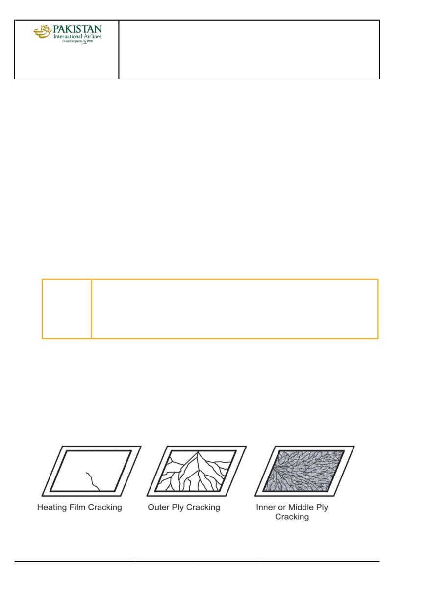
PROCEDURES
ABNORMAL AND EMERGENCY PROCEDURES
A318/A319/A320/A321
FLIGHT CREW
MISC
TECHNIQUES MANUAL
touch the affected glass with a pen or a finger nail to check if the crack(s) is(are) on the cockpit
side (Inner ply):
- If there is no crack on the cockpit side:
The Inner ply is not damaged. Therefore, the structural integrity is not affected: the
windshield/window is still able to sustain the differential pressure up to the maximum flight
level.
- If there are cracks on the cockpit side:
The Inner ply is damaged. The structural integrity of the window may be altered. As the
flight crew cannot easily identify if the Middle ply is also affected or not, the flight crew must
descend to FL 230/MEA in order to reduce the ΔP to 5 PSI.
Refer to FCOM/PRO-ABN-MISC [QRH] COCKPIT WINDSHIELD / WINDOW CRACKED
procedure to get the full procedure.
ADDITIONAL VISUAL CLUES:
In addition, visual clues can help the flight crew to assess which part of the window is affected
by the crack.
CAUTION
The visual clues given below are not sufficient to assess the structural integrity
of the window. The flight crew must do a physical check of the Inner ply of the
windshield as required by the COCKPIT WINDSHIELD/WINDOW CRACKED
procedure (Refer to FCOM/PRO-ABN-MISC [QRH] COCKPIT WINDSHIELD /
WINDOW CRACKED procedure) and apply the procedure accordingly.
A heating film cracking looks like roughly a straight line across the window starting from a
window edge. In most of the cases the line stops in the middle of the window.
An outer ply cracking usually shows a few broken lines that start from one edge of the
windshield or from a foreign object impact, and go through the window to another edge.
A structural ply cracking (Inner ply or Middle ply) has a break pattern that covers the entire
surface of the windshield. The small pieces of broken glass impair the visibility.
Typical Cockpit Window Damages
PIA A318/A319/A320/A321 FLEET
PR-AEP-MISC P 2/34
FCTM
← A
12 JAN 22
PROCEDURES
ABNORMAL AND EMERGENCY PROCEDURES
A318/A319/A320/A321
FLIGHT CREW
MISC
TECHNIQUES MANUAL
EMER DESCENT
Ident.: PR-AEP-MISC-00019302.0001001 / 04 SEP 18
Applicable to: ALL
The emergency descent should only be initiated on positive confirmation that cabin altitude and
rate of climb are excessive and uncontrollable. However, the flight crew must rely on the CAB PR
EXCESS CAB ALT warning, even if not confirmed on the CAB PRESS SD page. The CAB PR
EXCESS CAB ALT warning can be triggered by a cabin pressure sensor, different from the one used
to control the pressure and display the cabin altitude on the SD.
The flight crew should perform the actions of the EMER DESCENT in two steps:
- First step: Apply the memory items.
- Second step: Perform the read-&-do procedure (ECAM or QRH).
During the first step, the PM should focus on monitoring the FMA to ensure that the PF had correctly
established the aircraft in descent.
During the second step, the PF should refine the settings.
To initiate the emergency descent, the use of autopilot (AP) and autothrust is highly recommended.
At high flight levels, the flight crew should extend the speed brakes while monitoring the VLS. This is
in order to avoid the activation of the angle of attack protection which may result in the retraction of
the speed brakes and in AP disconnection.
Note:
When in IDLE thrust, high speed and with speed brake extended, the rate of descent is
approximately 7 000 ft/min. To descend from FL 390 to FL 100, it takes approximately
4 min and 40 NM.
The flight crew should be aware that the MORA displayed on ND is the highest MORA value
within a radius of 40 NM around the aircraft.
The flight crew should suspect structural damage in case of a loud bang, or high cabin vertical
speed. If the flight crew suspects structural damage, apply both of the following:
- Set the SPEED/MACH pb to SPEED, to prevent an increase in the IAS, or to reduce the speed.
This action minimizes the stress on aircraft structure
- Carefully use the speed brakes, to avoid additional stress on aircraft structure.
If the cabin altitude goes above 14 000 ft, the flight crew must press the MASK MAN ON pb. When it
is obvious that the cabin altitude will exceed 14 000 ft, the flight crew could press the MASK MAN ON
pb, before the cabin altitude reaches 14 000 ft.
The TCAS mode selector must remain on the TA/RA position. Avoidance of collision has the priority,
even if it requires one temporary interruption of the descent maneuver. The TA/RA TCAS mode
enables a maximum protection against collision.
PIA A318/A319/A320/A321 FLEET
PR-AEP-MISC P 3/34
FCTM
B →
12 JAN 22
PROCEDURES
ABNORMAL AND EMERGENCY PROCEDURES
A318/A319/A320/A321
FLIGHT CREW
MISC
TECHNIQUES MANUAL
Finally, subsequent to an emergency descent, once the oxygen masks are removed, the flight crew
should perform all of the following:
- Close the oxygen stowage mask compartment.
- Press the PRESS TO RESET oxygen control slide, to deactivate the mask microphone, and to cut
off the oxygen.
Below FL 100, the flight crew should limit the rate of descent to approximately 1 000 ft/min, except
during the approach phase.
PIA A318/A319/A320/A321 FLEET
PR-AEP-MISC P 4/34
FCTM
← B →
12 JAN 22
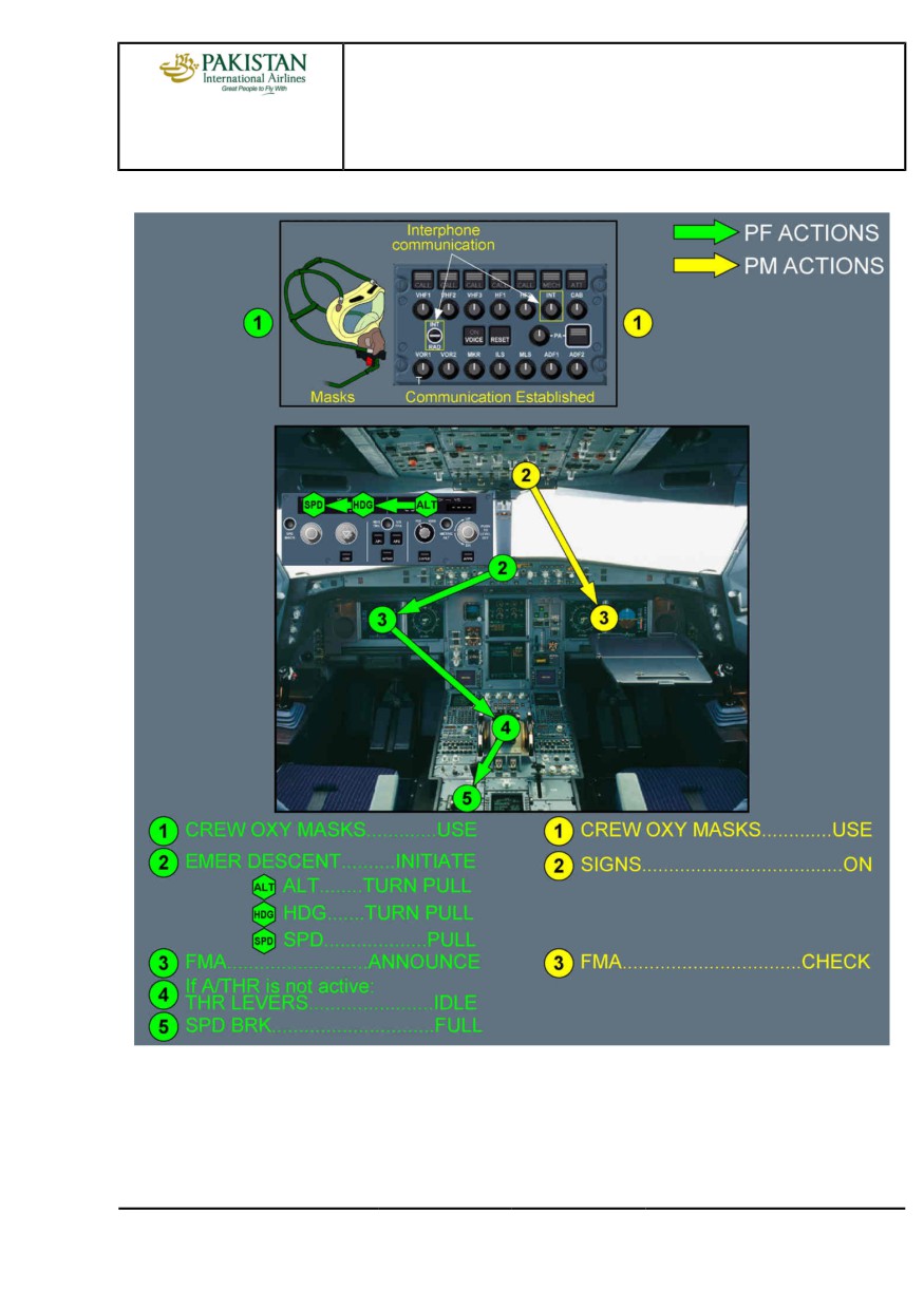
PROCEDURES
ABNORMAL AND EMERGENCY PROCEDURES
A318/A319/A320/A321
FLIGHT CREW
MISC
TECHNIQUES MANUAL
EMER DESCENT - Memory Items
PIA A318/A319/A320/A321 FLEET
PR-AEP-MISC P 5/34
FCTM
← B
12 JAN 22
PROCEDURES
ABNORMAL AND EMERGENCY PROCEDURES
A318/A319/A320/A321
FLIGHT CREW
MISC
TECHNIQUES MANUAL
EMER EVAC
Applicable to: ALL
Ident.: PR-AEP-MISC-A-00019303.0001001 / 20 MAR 17
GENERAL
The typical case, which may require an emergency evacuation, is an uncontrollable on ground
engine fire. This situation, which may occur following a rejected takeoff or after landing, requires
good crew coordination to cope with a high workload situation:
- In the rejected takeoff case, the Captain calls "STOP". This confirms that the Captain has
controls
- In all other cases, the Captain calls "I HAVE CONTROL" if required, to state the control hand
over.
Note:
If possible, position the aircraft to keep the fire away from the fuselage, taking into
account the wind direction.
Ident.: PR-AEP-MISC-A-00016352.0002001 / 20 MAR 17
DECISION MAKING
As soon as aircraft is stopped, and the parking brake is set, the captain notifies the cabin crew and
calls for ECAM ACTIONS. At this stage, the task sharing is defined as follow:
- The first officer carries out the ECAM actions
- The captain builds up his decision to evacuate depending on the circumstances. Considerations
should be given to:
• Fire remaining out of control after having discharged the agents
• Possible passenger evacuation of the aircraft on the runway
• Communicating intentions or requests to ATC.
If fire remains out of control after having discharged the fire agents, the captain calls for the EMER
EVAC procedure.
Ident.: PR-AEP-MISC-A-00019304.0001001 / 04 NOV 20
EVACUATION PROCEDURE
The EMER EVAC procedure is located in the inside back cover of the QRH. The flight crew must
refer to this procedure, if an evacuation is required for another reason than an engine fire.
PIA A318/A319/A320/A321 FLEET
PR-AEP-MISC P 6/34
FCTM
C →
12 JAN 22