Airbus A318/319/320/321. FLIGHT CREW TECHNIQUES MANUAL (2005-2022) - page 7
AIRCRAFT SYSTEMS
WEATHER RADAR
A318/A319/A320/A321
FLIGHT CREW
TECHNIQUES MANUAL
Use of Reduced gain to Identify Heaviest Rainfall
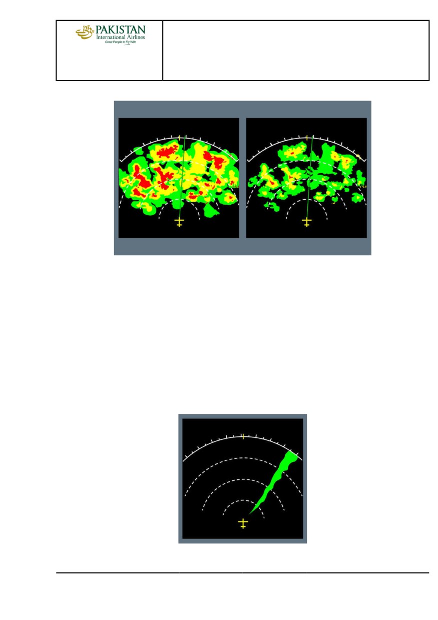
RADAR INTERFERENCE
High power external radio frequency sources that operate at a frequency next to the frequency of
the weather radar may create interferences. These interferences may result in a not usual return
display on the ND. The radar return will appear as a single wedge that extends out along the ND
toward the source of interference.
The width and color of the interference may differ on the ND, depending on the distance to the
source and its strength.
This interference does not damage the radar system, and will disappear as soon as the source of
interference is outside the limit of the radar scan zone.
Note:
Radar interference may also be known as ‘spoking’ or ‘alien radar’.
Radar Interference
PIA A318/A319/A320/A321 FLEET
AS-WXR P 13/20
FCTM
← C
12 JAN 22
AIRCRAFT SYSTEMS
WEATHER RADAR
A318/A319/A320/A321
FLIGHT CREW
TECHNIQUES MANUAL
OPERATIONS IN CONVECTIVE WEATHER
Ident.: AS-WXR-00019768.0001001 / 26 NOV 19
Applicable to: ALL
The flight crew should apply the following operational recommendations in convective weather
conditions. These recommendations are applicable in addition to basic knowledge of meteorology
and of operation in adverse weather conditions.
PIA A318/A319/A320/A321 FLEET
AS-WXR P 14/20
FCTM
D →
12 JAN 22
AIRCRAFT SYSTEMS
WEATHER RADAR
A318/A319/A320/A321
FLIGHT CREW
TECHNIQUES MANUAL
Weather detection:
- Always consider that a convective cloud may be dangerous, even if the weather echo is weak.
Remember that the weather radar detects only water droplets
- Frequent lightning may indicate an area with high probability of severe turbulence
- Remember that the TURB function detects areas of wet turbulence only
Avoidance decision:
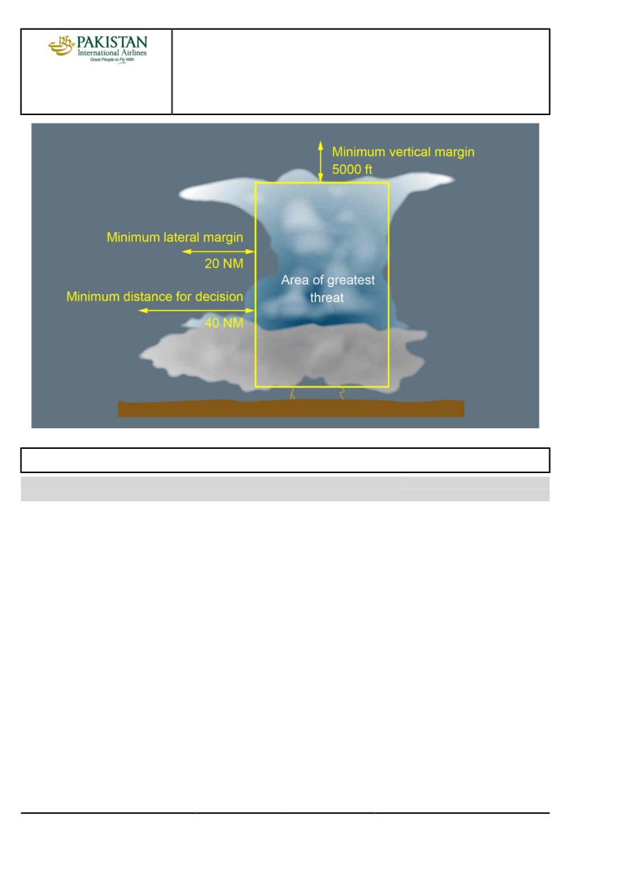
- Establish an "area of greatest threat" based on the locations and shape of the strongest weather
radar echoes, and on the meteorological knowledge of the flight crew. This "area of greatest
threat" corresponds to the zone where the flight crew estimates that the weather conditions are
too dangerous to fly in
- The weather hazard prediction function (if installed) indicates zones with a high probability of
weather hazards (hail or lightning). Avoidance of the detected weather always has priority over
avoidance of the weather hazards. As a priority, apply the recommendations to avoid storms,
and avoid hazard areas as much as possible
- Initiate your avoidance maneuver as early as possible. As the aircraft gets nearer to the
convective weather zone, the information from the weather radar often becomes partial.
Consider a minimum distance of 40 NM from the convective cloud to make the decision for
avoidance maneuver.
Avoidance technique:
- If possible, perform lateral avoidance instead of vertical avoidance. Vertical avoidance is
in general not recommended, particularly at high altitude, due to the reduction of buffet
and performance margins. In addition, some convective clouds may have a significant and
unpredictable build-up speed.
- Lateral avoidance:
• If possible, deviate upwind instead of downwind. Usually, there is less turbulence and hail
upwind of a convective cloud
• If possible, avoid the identified “area of greatest threat” by at least 20 NM
• Apply an additional margin if the convective clouds are very dynamic
- Vertical avoidance:
• Avoid flying below a convective cloud, even in visual conditions, due to possible severe
turbulence, windshear, microbursts, lightning strikes and hail. If an aircraft must fly below a
convective cloud, the flight crew should take into account all indications (visual judgement,
weather radar, weather report, pilot’s report, etc.) before they take the final decision
• For flight above a convective cloud, apply a vertical margin of 5 000 ft from the identified
“area of greatest threat”.
PIA A318/A319/A320/A321 FLEET
AS-WXR P 15/20
FCTM
← D →
12 JAN 22
AIRCRAFT SYSTEMS
WEATHER RADAR
A318/A319/A320/A321
FLIGHT CREW
TECHNIQUES MANUAL
ICE CRYSTALS
Ident.: AS-WXR-00021072.0001001 / 06 JUL 17
Applicable to: ALL
GENERAL
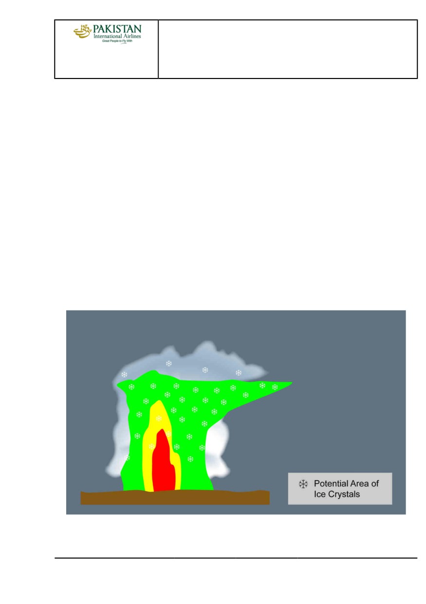
Clouds are made of particles of water that can be either liquid or solid. Ice crystals are very small
solid water particles. In some areas, there may be a very high concentration of ice crystals that
may have adverse effect on the aircraft.
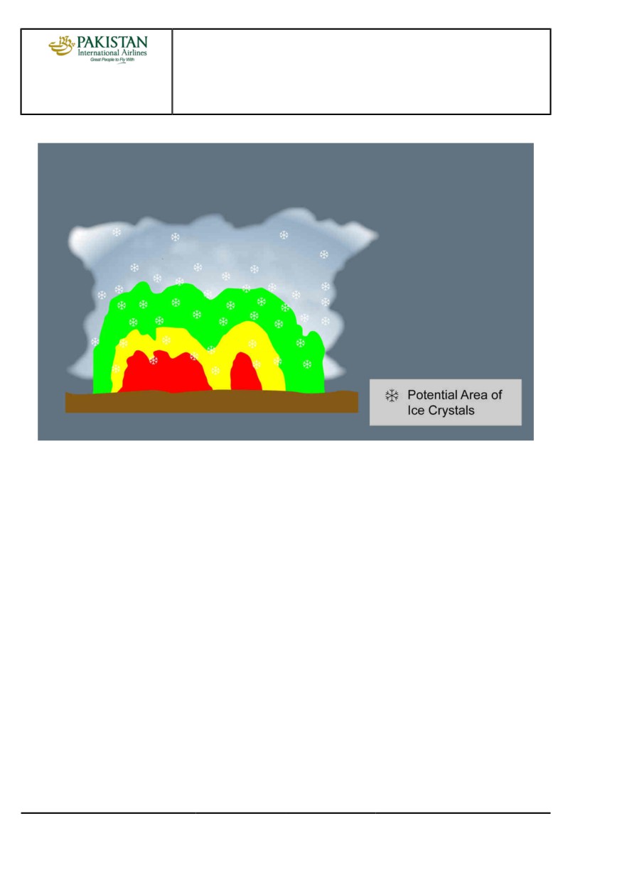
Areas of ice crystals are usually next to, or above the core of convective clouds that have
high-intensity precipitation. However, areas of ice crystals may sometimes even be several
nautical miles away from the core of the associated convective cloud.
When ice crystals get in contact with a hot surface, they melt. Depending on the type of surface,
a water film may appear. On the windshield, this water film creates not-expected appearance of
“rain” at temperatures too low for liquid water to exist.
If there is a specific airflow towards a zone of the aircraft where water can build up, accretion may
occur and create a block of ice. This is why flight in areas of ice crystals may result in various
effects, for example engine vibrations, engine power loss, engine damage, or icing of air data
probes.
PIA A318/A319/A320/A321 FLEET
AS-WXR P 16/20
FCTM
← D to E →
12 JAN 22
AIRCRAFT SYSTEMS
WEATHER RADAR
A318/A319/A320/A321
FLIGHT CREW
TECHNIQUES MANUAL
DETECTION OF ICE CRYSTALS
Ice crystals are difficult to detect with the weather radar, because their reflectivity is very low due
to both their small size and solid state. In addition, in areas of ice crystals, the flight crew should
not expect significant icing of the airframe. This is because ice crystals bounce off cold aircraft
surfaces. This is why even the ice detection system does not detect ice crystals, because ice
crystals do not build up on ice detectors and visual ice indicators.
However, areas of ice crystals are usually associated with visible moisture. Ice crystals can be
indicated by one or more of the following:
- Appearance of rain on the windshield at temperatures too low for rain to exist. This “rain” is
usually associated with a “Shhhh” noise
- Small accumulation of ice particles on wipers
- Smell of ozone or Saint Elmo’s fire
- Aircraft TAT indication that remains near 0 °C (due to freezing of the TAT probe)
- Light to moderate turbulence in IMC at high altitude
- No significant radar echo at high aircraft altitude, combined with:
• High-intensity precipitation that appears below the aircraft, or
• Aircraft position downwind of a very active convective cloud.
Isolated Continental Thunderstorm
PIA A318/A319/A320/A321 FLEET
AS-WXR P 17/20
FCTM
← E →
12 JAN 22
AIRCRAFT SYSTEMS
WEATHER RADAR
A318/A319/A320/A321
FLIGHT CREW
TECHNIQUES MANUAL
Mesoscale Convective Cloud
OPERATIONAL RECOMMENDATIONS FOR ICE CRYSTALS
If possible, the flight crew should avoid flight into areas that have a high concentration of ice
crystals. The following recommendations apply:
- Use the weather radar:
• Identify areas that have a strong echo, and perform a detailed analysis of the structure of the
convective clouds
• If necessary, use the weather radar manual modes for a more precise analysis
• Pay particular attention to strong echoes below the aircraft and to downwind areas.
- To avoid convective clouds, comply with operational recommendations (Refer to AS-WXR
Operations in Convective Weather), particularly:
• Prefer lateral to vertical avoidance
• Comply with the avoidance margins
• Deviate upwind instead of downwind.
PIA A318/A319/A320/A321 FLEET
AS-WXR P 18/20
FCTM
← E →
12 JAN 22
AIRCRAFT SYSTEMS
WEATHER RADAR
A318/A319/A320/A321
FLIGHT CREW
TECHNIQUES MANUAL
If the aircraft encounters ice crystals precipitation despite avoidance action, and if this results in
engines or probes misbehaviors, the published procedures and recommendations apply, and in
particular:
- ECAM alerts related to engine failure or engine stall
- ECAM alerts related to probe failure
- QRH procedures such as the ones linked to unreliable airspeed indication, engine vibrations,
engine relight in flight…
PIA A318/A319/A320/A321 FLEET
AS-WXR P 19/20
FCTM
← E
12 JAN 22
AIRCRAFT SYSTEMS
WEATHER RADAR
A318/A319/A320/A321
FLIGHT CREW
TECHNIQUES MANUAL
Intentionally left blank
PIA A318/A319/A320/A321 FLEET
AS-WXR P 20/20
FCTM
12 JAN 22
PROCEDURES
Intentionally left blank
PROCEDURES
PRELIMINARY PAGES
A318/A319/A320/A321
FLIGHT CREW
TABLE OF CONTENTS
TECHNIQUES MANUAL
PR-NP Normal Procedures
PR-NP-GEN General
General
A
Communication
B
Clean Cockpit
C
Secured and Transit Stop
D
PR-NP-SOP Standard Operating Procedures
PR-NP-SOP-40 Preliminary Cockpit Preparation
Objectives
A
Use of APU Bleed
B
Oxygen
C
Preliminary Takeoff Performance Computation
D
PR-NP-SOP-50 Exterior Walkaround
Exterior Walkaround
A
PR-NP-SOP-60 Cockpit Preparation
ADIRS Operations
A
FMGS Preparation
B
PR-NP-SOP-70 Before Pushback or Start
Takeoff Data
A
Seating Position and Adjustment of Rudder Pedals
B
PR-NP-SOP-100 Taxi
Brakes
A
Flight Controls
B
Taxi Roll and Steering
C
180 degrees Turn on Runway
D
Last Data Changes Before Takeoff
E
Departure Briefing Confirmation
F
ADIRS Alignment
G
PR-NP-SOP-110 Before Takeoff
Packs
A
Continued on the following page
PIA A318/A319/A320/A321 FLEET
PR-PLP-TOC P 1/8
FCTM
12 JAN 22
PROCEDURES
PRELIMINARY PAGES
A318/A319/A320/A321
FLIGHT CREW
TABLE OF CONTENTS
TECHNIQUES MANUAL
Continued from the previous page
PR-NP-SOP-120 Takeoff
Thrust Setting
A
Takeoff Roll
B
Rotation
C
Tail Strike Avoidance
D
Acceleration Altitude
E
Slats/Flaps Retraction at Heavy Weight
F
Overspeed Warning During Slats/Flaps Transition
G
Low Altitude Level Off
H
Noise Abatement Takeoff
I
PR-NP-SOP-140 Climb
Climb Modes
A
Small Altitude Changes
B
Speed Considerations
C
Vertical Performance Predictions
D
Lateral Navigation
E
Undue Activation of Go-Around Phase
F
PR-NP-SOP-150 Cruise
FMS Use
A
Cost Index
B
Speed Considerations
C
Speed Decay During Cruise
D
Altitude Considerations
E
Step Climb
F
Fuel Temperature
G
PR-NP-SOP-160 Descent Preparation
Landing Performance
A
Content of a Landing Performance Data Crosscheck
B
Brakes Oxidation
C
Approach Preparation
D
PR-NP-SOP-170 Descent
Computation Principles
A
Guidance and Monitoring
B
PR-NP-SOP-180 Holding
Holding Speed and Configuration
A
In the Holding Pattern
B
Continued on the following page
PIA A318/A319/A320/A321 FLEET
PR-PLP-TOC P 2/8
FCTM
12 JAN 22
PROCEDURES
PRELIMINARY PAGES
A318/A319/A320/A321
FLIGHT CREW
TABLE OF CONTENTS
TECHNIQUES MANUAL
Continued from the previous page
PR-NP-SOP-190 Approach
PR-NP-SOP-190-GEN General
Introduction
A
Discontinued Approach
B
PR-NP-SOP-190-CONF Configuration Management
Initial Approach
A
Intermediate Approach
B
Final Approach
C
PR-NP-SOP-190-GUI Guidance Management
Approach using LOC G/S Guidance
A
Approach using LOC G/S for CATII CATIII
B
Approach using FINAL APP Guidance
C
Approach using FPA Guidance
D
Circling Approach
E
Visual Approach
F
ILS RAW DATA
G
PR-NP-SOP-250 Landing
Approach and landing techniques
A
Transition to Visual References
B
Flare and Touchdown
C
Rollout
D
Deceleration
E
Tail Strike Avoidance
F
PR-NP-SOP-260 Go-Around
General
A
Considerations about Go-Around
B
AP/FD Go-Around Phase Activation
C
Go-Around Phase
D
Engines Acceleration
E
Leaving the Go-Around Phase
F
PR-NP-SOP-270 After Landing
Use of Brake Fans
A
PR-NP-SOP-280 Parking
Use of APU Bleed
A
Continued on the following page
PIA A318/A319/A320/A321 FLEET
PR-PLP-TOC P 3/8
FCTM
12 JAN 22
PROCEDURES
PRELIMINARY PAGES
A318/A319/A320/A321
FLIGHT CREW
TABLE OF CONTENTS
TECHNIQUES MANUAL
Continued from the previous page
PR-NP-CL Normal Checklists
General
A
Cockpit Preparation
B
Before Start
C
After Start
D
Taxi
E
Line-Up
F
Departure Change
G
Approach
H
Landing
I
After Landing
J
Parking
K
Securing the Aircraft
L
PR-NP-SP Supplementary Procedures
PR-NP-SP-10 Adverse Weather
PR-NP-SP-10-10-1 Cold Weather Operations and Icing Conditions
General
A
Exterior Inspection
B
Cockpit Preparation
C
Aircraft Deicing/Anti-Icing on Ground
D
Taxi-Out
E
Takeoff
F
In Flight
G
Landing
H
Taxi-in
I
PR-NP-SP-10-10-2 Windshear
General
A
Operational Recommendations
B
PR-NP-SP-10-10-3 Weather Turbulence
Introduction
A
TAKEOFF
B
IN FLIGHT
C
Landing
D
PR-NP-SP-10-10-4 Wake Turbulence
Wake Turbulence
A
Continued on the following page
PIA A318/A319/A320/A321 FLEET
PR-PLP-TOC P 4/8
FCTM
12 JAN 22
PROCEDURES
PRELIMINARY PAGES
A318/A319/A320/A321
FLIGHT CREW
TABLE OF CONTENTS
TECHNIQUES MANUAL
Continued from the previous page
PR-NP-SP-20 Green Operating Procedures
General
A
Dispatch
B
Preliminary Cockpit Preparation
C
External Walkaround
D
Cockpit Preparation
E
Before Pushback or Start
F
After Start
G
Taxi
H
Before Takeoff
I
Climb
J
Cruise
K
Descent Preparation
L
Descent
M
Holding
N
Approach
O
After Landing
P
PR-NP-SP-30 Radius to Fix (RF) Legs
Radius to Fix (RF) Legs
A
PR-NP-SP-40 Touch and Go
Touch and Go
A
PR-NP-SP-50 Stop and Go
Stop and Go
A
PR-AEP Abnormal and Emergency Procedures
PR-AEP-GEN General
Introduction
A
PR-AEP-AUTOFLT AUTO FLIGHT
FMGC Failure
A
PR-AEP-BRK BRAKES
Loss of Braking
A
PR-AEP-ELEC ELEC
Introduction to Emergency Electrical Configuration
A
Technical Background
B
General Guidelines
C
Remaining Systems
D
Continued on the following page
PIA A318/A319/A320/A321 FLEET
PR-PLP-TOC P 5/8
FCTM
12 JAN 22
PROCEDURES
PRELIMINARY PAGES
A318/A319/A320/A321
FLIGHT CREW
TABLE OF CONTENTS
TECHNIQUES MANUAL
Continued from the previous page
PR-AEP-ENG ENG
Engine Abnormal response
A
All Engines Failure
B
Engine Failure - General
C
Engine Failure at Low Speed (on ground)
D
Engine Failure after V1
E
Engine Failure During Initial Climb
F
Engine Failure During Cruise
G
Engine Stall
H
Engine Tailpipe Fire
I
Engine Vibrations
J
One Engine Inoperative - Circling
K
One Engine Inoperative - Go-Around
L
One Engine Inoperative - Landing
M
Thrust Levers Management in the Case of Inoperative Reverser(s)
N
PR-AEP-F_CTL F/CTL
Abnormal Flaps/Slats Configuration
A
PR-AEP-FUEL FUEL
Fuel Leak
A
Fuel Overread
B
PR-AEP-HYD HYD
Hydraulic Generation Particularities
A
Dual Hydraulic Failures
B
Remaining Systems
C
PR-AEP-LG L/G
Landing with Abnormal L/G
A
Nose Wheel Steering Fault
B
Taxi with Deflated or Damaged Tires
C
Wheel Tire Damage Suspected
D
WHEEL Tire Damage Suspected
E
PR-AEP-MISC MISC
Cockpit Windshield/Window Cracked
A
EMER DESCENT
B
EMER EVAC
C
EMER LANDING
D
Flight Crew Incapacitation
E
Handling the Aircraft in the Case of Severe Damage
F
Continued on the following page
PIA A318/A319/A320/A321 FLEET
PR-PLP-TOC P 6/8
FCTM
12 JAN 22
PROCEDURES
PRELIMINARY PAGES
A318/A319/A320/A321
FLIGHT CREW
TABLE OF CONTENTS
TECHNIQUES MANUAL
Continued from the previous page
Low Energy
G
Overspeed
H
OVERWEIGHT LANDING
I
Rejected Takeoff
J
Stall Recovery
K
Volcanic Ash Encounter
L
Upset Prevention and Recovery
M
PR-AEP-NAV NAV
ADR/IRS FAULT
A
Unreliable Airspeed Indications
B
"Unreliable Speed Indication" QRH Procedure
C
Dual Radio Altimeter Failure
D
PR-AEP-SMOKE SMOKE
Introduction
A
Smoke / Fumes Detection and Procedure Application
B
Coordination with Cabin Crew
C
Smoke / Fumes / AVNCS Smoke QRH Procedure
D
Lithium Battery Fire in the Cockpit
E
Cargo Smoke
F
PIA A318/A319/A320/A321 FLEET
PR-PLP-TOC P 7/8
FCTM
12 JAN 22
PROCEDURES
PRELIMINARY PAGES
A318/A319/A320/A321
FLIGHT CREW
TABLE OF CONTENTS
TECHNIQUES MANUAL
Intentionally left blank
PIA A318/A319/A320/A321 FLEET
PR-PLP-TOC P 8/8
FCTM
12 JAN 22

PROCEDURES
PRELIMINARY PAGES
A318/A319/A320/A321
FLIGHT CREW
SUMMARY OF HIGHLIGHTS
TECHNIQUES MANUAL
Localization
Toc
ID
Reason
Title
Index
PR-NP-GEN
C
1
Documentation update: Addition of "Clean Cockpit" documentary
Clean Cockpit
unit
PR-NP-GEN
C
2
Effectivity update: The information no longer applies to all MSN.
Clean Cockpit
PR-NP-SOP-100
A
1
Effectivity update: The information now also applies to MSN
Brake Check
05152, 05162, 05253, 05746.
PR-NP-SOP-190-GUI
C
1
Effectivity update: The information now also applies to MSN
Reaching Minima
05152, 05162, 05253, 05746.
PR-NP-SOP-190-GUI
D
2
Effectivity update: The information now also applies to MSN
Back Course Localizer Approach
05152, 05162, 05253, 05746.
PR-NP-SOP-260
C
1
Effectivity update: The information now also applies to MSN
AP/FD Go-Around Phase Activation
05152, 05162, 05253, 05746.
PR-NP-SOP-260
D
2
Effectivity update: The information now also applies to MSN
Go-Around Phase
05152, 05162, 05253, 05746.
PR-AEP-BRK
A
1
Effectivity update: The information now also applies to MSN
Loss of Braking
05152, 05162, 05253, 05746.
PR-AEP-ENG
B
1
Effectivity update: The information now also applies to MSN
Introduction
05152, 05162, 05253, 05746.
PR-AEP-ENG
B
2
Effectivity update: The information now also applies to MSN
Technical Background
05152, 05162, 05253, 05746.
PR-AEP-ENG
B
3
Effectivity update: The information now also applies to MSN
General Philosophy
05152, 05162, 05253, 05746.
PR-AEP-HYD
C
1
Effectivity update: The information now also applies to MSN
Remaining Systems
05152, 05162, 05253, 05746.
PR-AEP-LG
D
1
Effectivity update: The information now also applies to MSN
Wheel Tire Damage Suspected
05152, 05162, 05253, 05746.
PR-AEP-MISC
D
1
Effectivity update: The information now also applies to MSN
EMER LANDING
05152, 05162, 05253, 05746.
PR-AEP-MISC
K
2
Effectivity update: The information now also applies to MSN
Stall Recognition
05152, 05162, 05253, 05746.
PR-AEP-MISC
K
3
Effectivity update: The information now also applies to MSN
Stall Warning at Liftoff
05152, 05162, 05253, 05746.
PR-AEP-NAV
A
1
Effectivity update: The information now also applies to MSN
ADR/IRS FAULT
05152, 05162, 05253, 05746.
PR-AEP-NAV
C
2
Effectivity update: The information now also applies to MSN
"Unreliable Speed Indication" QRH
05152, 05162, 05253, 05746.
Procedure
PIA A318/A319/A320/A321 FLEET
PR-PLP-SOH P 1/2
FCTM
12 JAN 22
PROCEDURES
PRELIMINARY PAGES
A318/A319/A320/A321
FLIGHT CREW
SUMMARY OF HIGHLIGHTS
TECHNIQUES MANUAL
Intentionally left blank
PIA A318/A319/A320/A321 FLEET
PR-PLP-SOH P 2/2
FCTM
12 JAN 22
PROCEDURES
NORMAL PROCEDURES
A318/A319/A320/A321
FLIGHT CREW
GENERAL
TECHNIQUES MANUAL
GENERAL
Ident.: PR-NP-GEN-00018667.0001001 / 20 MAR 17
Applicable to: ALL
The Normal Procedures chapter outlines the techniques that the flight crew should apply during
each flight phase, in order to optimize the use of the aircraft. The flight crew should read the Normal
Procedures chapter in conjunction with the FCOM, which provides the normal procedures and their
associated tasksharing, callouts, and checklists.
All of these flying techniques are applicable to normal conditions.
COMMUNICATION
Ident.: PR-NP-GEN-00018668.0001001 / 20 MAR 17
Applicable to: ALL
CROSS-COCKPIT COMMUNICATION
The term "cross-cockpit communication" refers to communication between the PF and the PM.
This communication is important for any flight crew. Each time one flight crewmember adjusts or
changes information and/or equipment on the flight deck, the other flight crewmember must be
informed, and an acknowledgement must be obtained.
Such adjustments and changes include:
- FMGS alterations
- Changes in speed or Mach
- Tuning navigation aids
- Flight path modifications
- System selections (e.g. anti-ice system).
When using cross-cockpit communication, standard phraseology is essential to ensure
effective flight crew communication. This phraseology should be concise and exact. Refer to
FCOM/PRO-NOR-SCO Communications and Standard Terms
In addition to the standard callout, the flight crew should communicate to enhance situation
awareness. As per PM role and in accordance with the Airbus golden rules, the PM should monitor
and announce any situation that requires PF reaction or should takeover, when necessary.
This is the case for any deviation from the intended flight path, or any case that requires a new
assessment of the flight situation and of the flight crew's intention.
STERILE COCKPIT RULE
When the aircraft is below 10 000 ft, any conversation that is not essential should be avoided: This
includes conversations that take place in the cockpit, or between the flight crew and cabin crew.
It is important to adhere to this policy, in order to facilitate communication between both of the
PIA A318/A319/A320/A321 FLEET
PR-NP-GEN P 1/6
FCTM
A to B →
12 JAN 22
PROCEDURES
NORMAL PROCEDURES
A318/A319/A320/A321
FLIGHT CREW
GENERAL
TECHNIQUES MANUAL
flight crew, and to ensure the effective communication of emergency or safety-related information,
between flight and cabin crew members.
CLEAN COCKPIT
1 Ident.: PR-NP-GEN-00018669.0002001 / 04 NOV 20
Criteria: 25-1BPJ, SA
Applicable to: MSN 05746
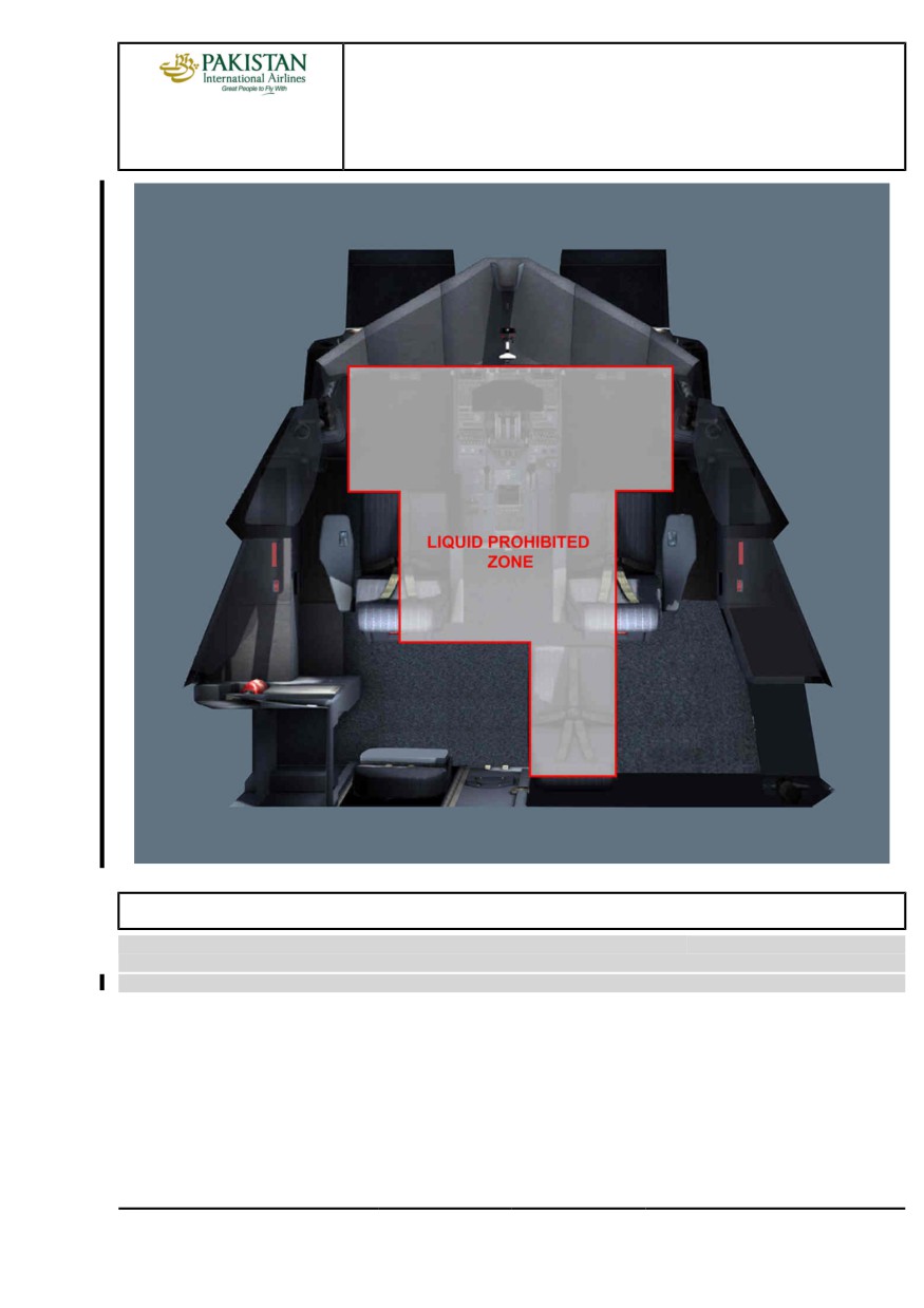
Objects not stored in their dedicated area in the cockpit may fall and cause hazards such as damage
to the equipment or inadvertent operations of the controls, or pushbuttons.
Airbus highly recommends that the flight crews put and store all objects in their dedicated area in the
cockpit:
- Cups with lids in the cup holders
- Bottles with caps in the bottle holders
- Books and paper, if any, in the lateral stowage
- Trash in the waste bin in the lateral console
- Meal trays on the floor behind the flight crew. The flight attendants should collect the meal trays as
soon as possible
- Personal equipment properly secured in the various stowage areas
- Portable electronic devices properly secured in the flight document stowage, in the checklist
stowage or in the operation manual stowage (Refer to FCOM/DSC-25-10-10 General
Arrangement).
CAUTION
The flight crew must carefully handle liquids in the cockpit area in accordance with
the liquid prohibited zone in order to avoid any damage to equipment or inadvertent
operation of controls.
The flight crew must always ensure that the cups are equipped with lids and bottles
equipped with caps.
PIA A318/A319/A320/A321 FLEET
PR-NP-GEN P 2/6
FCTM
← B to C →
12 JAN 22
PROCEDURES
NORMAL PROCEDURES
A318/A319/A320/A321
FLIGHT CREW
GENERAL
TECHNIQUES MANUAL
CLEAN COCKPIT
Ident.: PR-NP-GEN-00018669.0001001 / 04 NOV 20
Criteria: SA
2 Applicable to: MSN 02155-05253, 07784-07792
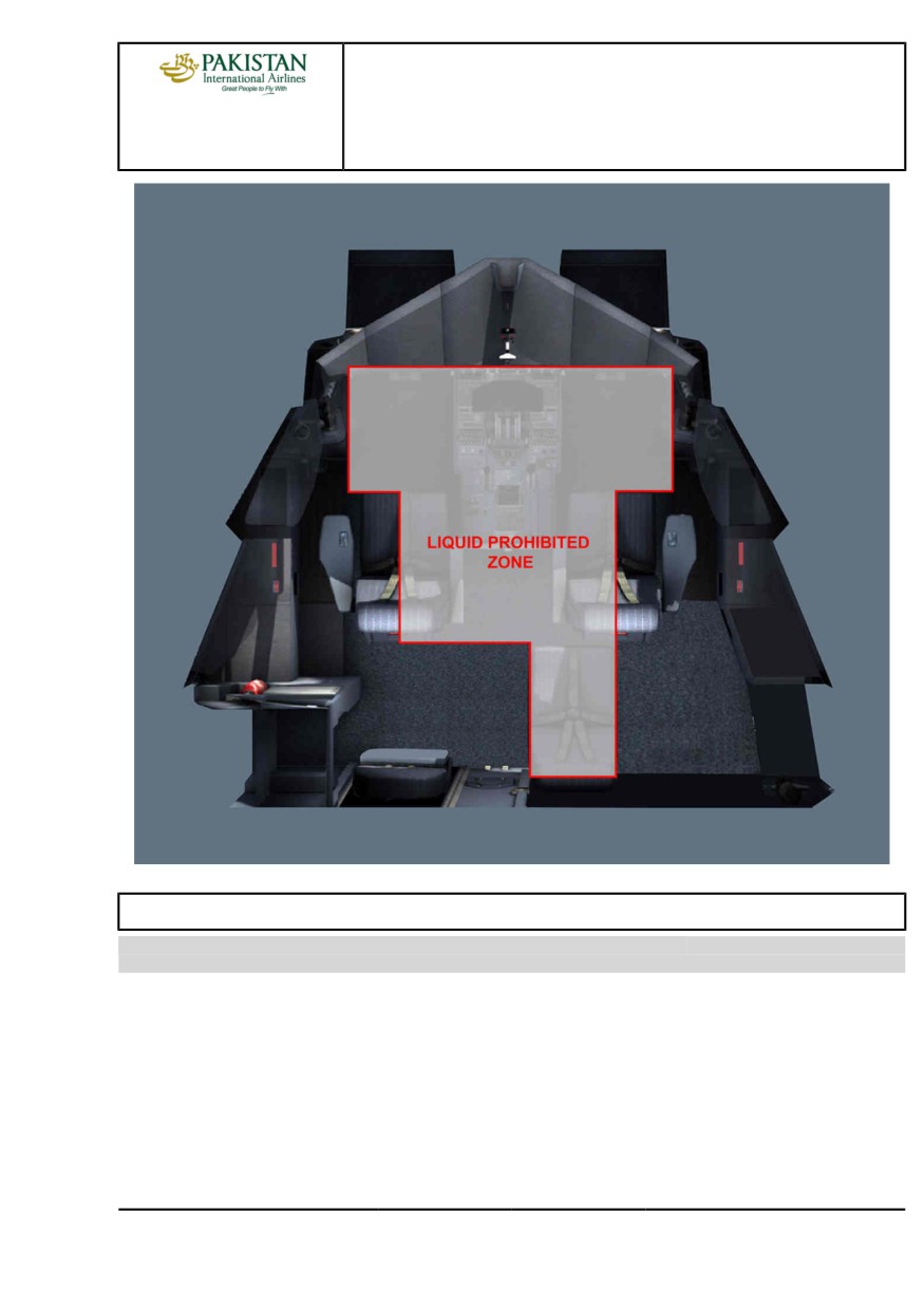
Objects not stored in their dedicated area in the cockpit may fall and cause hazards such as damage
to the equipment or inadvertent operations of the controls, or pushbuttons.
Airbus highly recommends that the flight crews put and store all objects in their dedicated area in the
cockpit:
- Cups with lids in the cup holders
- Bottles with caps in the bottle holders
- Books and paper, if any, in the lateral stowage
PIA A318/A319/A320/A321 FLEET
PR-NP-GEN P 3/6
FCTM
← C →
12 JAN 22
PROCEDURES
NORMAL PROCEDURES
A318/A319/A320/A321
FLIGHT CREW
GENERAL
TECHNIQUES MANUAL
- Trash in the waste bin in the lateral console
- Meal trays on the floor behind the flight crew. The flight attendants should collect the meal trays as
soon as possible
- Personal equipment properly secured in the various stowage areas
- Portable electronic devices properly secured in the flight document stowage (Refer to
FCOM/DSC-25-10-10 General Arrangement).
CAUTION
The flight crew must carefully handle liquids in the cockpit area in accordance with
the liquid prohibited zone in order to avoid any damage to equipment or inadvertent
operation of controls.
The flight crew must always ensure that the cups are equipped with lids and bottles
equipped with caps.
PIA A318/A319/A320/A321 FLEET
PR-NP-GEN P 4/6
FCTM
← C →
12 JAN 22
PROCEDURES
NORMAL PROCEDURES
A318/A319/A320/A321
FLIGHT CREW
GENERAL
TECHNIQUES MANUAL
SECURED AND TRANSIT STOP
Ident.: PR-NP-GEN-00018700.0001001 / 20 MAR 17
Applicable to: ALL
The aircraft is:
- in TRANSIT STOP when the last check list performed by the flight crew is the PARKING C/L
- in SECURED STOP when the last check list performed by the flight crew is the SECURING THE
AIRCRAFT C/L
The flight crew performs only the items indicated by an asterisk (*) in the Standard Operating
Procedures (SOP's) when there is no flight crew change and after a TRANSIT STOP.
PIA A318/A319/A320/A321 FLEET
PR-NP-GEN P 5/6
FCTM
← C to D →
12 JAN 22
PROCEDURES
NORMAL PROCEDURES
A318/A319/A320/A321
FLIGHT CREW
GENERAL
TECHNIQUES MANUAL
Otherwise, the flight crew performs all the items of the SOP's.
PIA A318/A319/A320/A321 FLEET
PR-NP-GEN P 6/6
FCTM
← D
12 JAN 22
PROCEDURES
NORMAL PROCEDURES
A318/A319/A320/A321
STANDARD OPERATING PROCEDURES
FLIGHT CREW
TECHNIQUES MANUAL
- PRELIMINARY COCKPIT PREPARATION
OBJECTIVES
Ident.: PR-NP-SOP-40-00018703.0001001 / 05 DEC 17
Applicable to: ALL
The objectives of the preliminary cockpit preparation are:
- To ensure that all safety checks are performed:
• The RCL pb is pressed for at least 3 s to display the cautions and warnings from the previous
flight.
• The technical logbook and MEL are checked at this stage.
- To check the liquid levels i.e. oil, hydraulic and oxygen pressure using
• The HYD pb is pressed to check the hydraulic level
• The ENG pb is pressed to check engine oil level (Refer to FCOM/PRO-NOR-SOP-04 Before
Walkaround - ECAM Pages)
• The DOOR pb is pressed, to check the oxygen pressure level
- To check the position of surface control levers e.g. slats/flaps, parking brake.
During the Preliminary Cockpit Preparation, the flight crew must also review all OEBs applicable to
the aircraft. The flight crew must pay a particular attention to the red OEBs, and more particularly to
the red OEBs that must be applied before the ECAM procedure.
USE OF APU BLEED
Ident.: PR-NP-SOP-40-00023388.0001001 / 26 NOV 19
Applicable to: ALL
Airbus SOP recommendation is to set the APU Bleed to ON when APU is available. However,
depending on the operational conditions and APU types, some odors may be perceived in the cabin,
once the APU Bleed is set to ON. This is due to the possible presence of oil traces in the APU
airduct.
Therefore, to further reduce potential odors in the Cabin, the APU Bleed may be selected 3 minutes
after APU start. This APU warm-up time enables the seals to reach their optimum performance and
eliminates oil traces in the APU airduct.
OXYGEN
Ident.: PR-NP-SOP-40-00018704.0001001 / 20 MAR 17
Applicable to: ALL
The ECAM DOOR/OXY SD page displays the oxygen pressure. When the oxygen pressure is below
a defined threshold, an amber half box highlights the value. This advises the flight crew that the
bottle should be refilled. The flight crew should refer to the minimum flight crew oxygen pressure
PIA A318/A319/A320/A321 FLEET
PR-NP-SOP-40 P 1/2
FCTM
A to C →
11 DEC 19
PROCEDURES
NORMAL PROCEDURES
A318/A319/A320/A321
STANDARD OPERATING PROCEDURES
FLIGHT CREW
TECHNIQUES MANUAL
- PRELIMINARY COCKPIT PREPARATION
(Refer to FCOM/LIM-OXY Minimum Flight Crew Oxygen Pressure). The prolonged dispatch of the
aircraft in such condition is not recommended.
PRELIMINARY TAKEOFF PERFORMANCE COMPUTATION
Ident.: PR-NP-SOP-40-00021838.0001001 / 05 DEC 17
Applicable to: ALL
ROLE OF THE PRELIMINARY TAKEOFF PERFORMANCE COMPUTATION
Usually, during the preliminary cockpit preparation phase, the workload of the flight crew is less
heavy than during future flight phases. The preliminary takeoff performance computation enables
both flight crewmembers to share a common view of the plan of action for the takeoff. It also
enables them to make the same assumptions for performance computations.
Both flight crewmembers enter the necessary data in their EFB TO PERF application. They must
take into account any applicable MEL/CDL items and NOTAMs, and independently compute the
preliminary takeoff performance data.
Then, both flight crewmembers crosscheck the results: they compare the EFB of the Captain with
the EFB of the First Officer for the parameters listed below. This crosscheck ensures the validity of
the computations.
CONTENT OF A PERFORMANCE DATA CROSSCHECK
When SOPs request a crosscheck of performance data, the flight crew must verify all of the
following values:
- Runway ident
This ensures that the runway used for the computation in the EFB and/or inserted in the FMS is
the same
- Takeoff shift
This ensures that the flight crew took into account the right intersection
- V speeds (V1, VR, V2)
- Greendot speed
This indirectly ensures that the GW values are consistent.
- Takeoff thrust (TOGA, FLEX, DERATED)
- FLAPS
- THS
- PACKS
- ANTI-ICE
- EO ACCEL ALT.
PIA A318/A319/A320/A321 FLEET
PR-NP-SOP-40 P 2/2
FCTM
← C to D
11 DEC 19
PROCEDURES
NORMAL PROCEDURES
A318/A319/A320/A321
FLIGHT CREW
STANDARD OPERATING PROCEDURES - EXTERIOR WALKAROUND
TECHNIQUES MANUAL
EXTERIOR WALKAROUND
Ident.: PR-NP-SOP-50-00018705.0001001 / 20 MAR 17
Applicable to: ALL
Standard Operating Procedures (SOP) outline the various elements that the flight crew must review
in greater detail. The objectives of the exterior inspection are:
- To obtain a global assessment of the aircraft status. Any missing parts or panels will be checked
against the Configuration Deviation List (CDL) for possible dispatch and any potential operational
consequences.
- To ensure that main aircraft surfaces are in adequate position relative to surface control levers.
- To check that there are no leaks e.g. engine drain mast, hydraulic lines.
- To check the status of the essential visible sensors i.e. AOA, pitot and static probes.
- To observe any possible abnormalities on the landing gear status:
• Wheels and tires status (cut, wear, cracks)
• Safety pins are removed
• Brakes status (Brake wear pin length with parking brake ON)
• Length of oleo. Any difference between the two main landing gears shall be reported.
- To observe any possible abnormality on the engines:
• Fan blades, turbine exhaust, engine cowl and pylon status
• Access door closed
• Correct closure/latching condition of the fan cowl doors.
• Safety pins are removed .
PIA A318/A319/A320/A321 FLEET
PR-NP-SOP-50 P 1/2
FCTM
A
22 MAR 17
PROCEDURES
NORMAL PROCEDURES
A318/A319/A320/A321
FLIGHT CREW
STANDARD OPERATING PROCEDURES - EXTERIOR WALKAROUND
TECHNIQUES MANUAL
Intentionally left blank
PIA A318/A319/A320/A321 FLEET
PR-NP-SOP-50 P 2/2
FCTM
22 MAR 17
PROCEDURES
NORMAL PROCEDURES
A318/A319/A320/A321
FLIGHT CREW
STANDARD OPERATING PROCEDURES - COCKPIT PREPARATION
TECHNIQUES MANUAL
ADIRS OPERATIONS
Ident.: PR-NP-SOP-60-00020405.0001001 / 20 MAR 17
Applicable to: ALL
The flight crew performs the alignment or realignment of the IRS during the cockpit preparation. This
action enables the IRS to operate in the NAV mode and to provide continuously the aircraft position.
The flight crew can perform:
- An alignment or a realignment of the IRS with a complete IRS alignment procedure
- A realignment of the IRS with a fast IRS alignment procedure.
The IRS alignment or realignment includes following two steps:
- Alignment:
Gyro and accelerometers prepare for the NAV computation.
- Position Initialization:
Navigation starting point is set.
ALIGNMENT STEP
COMPLETE IRS ALIGNMENT:
During a complete alignment, IRSs use the gravity and earth rotation to determinate the aircraft
attitude and true heading, and IRSs estimate a current aircraft latitude.
The IR mode selectors must be OFF for more than 5 s. Then, the flight crew sets the IR mode
selectors to the NAV mode.
Note:
The ON BAT light comes on during 5 s.
FAST IRS ALIGNMENT:
During a fast alignment, IRSs reset the ground speed and some internal filters to 0, but IRSs do
not estimate the aircraft position.
The flight crew sets the IR mode selectors to OFF then, back to the NAV mode within 5 s.
POSITION INITIALIZATION STEP
Refer to PR-NP-SOP-60 FMGS Preparation
CHECK OF ADIRS MODE
During the BEFORE START checklist, the flight crew checks that IRSs are in the NAV mode on
the MCDU.
PIA A318/A319/A320/A321 FLEET
PR-NP-SOP-60 P 1/6
FCTM
A
23 NOV 21
PROCEDURES
NORMAL PROCEDURES
A318/A319/A320/A321
FLIGHT CREW
STANDARD OPERATING PROCEDURES - COCKPIT PREPARATION
TECHNIQUES MANUAL
FMGS PREPARATION
Ident.: PR-NP-SOP-60-00018725.0002001 / 09 NOV 21
Applicable to: ALL
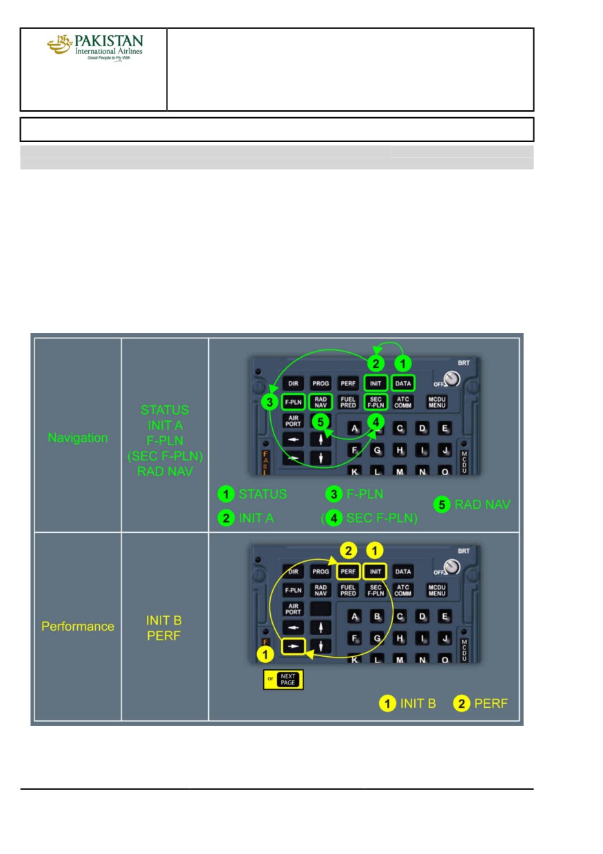
FMGS programming involves inserting navigation data, then performance data. It is to be noted that:
- Boxed fields must be filled
- Blue fields inform the crew that entry is permitted
- Green fields are used for FMS generated data, and cannot be changed
- Magenta characters identify limits (altitude, speed or time), that FMS will attempt to meet
- Yellow characters indicate a temporary flight plan display
- Amber characters signify that the item being displayed is important and requires immediate action
- Small font signifies that data is FMS computed
- Large font signifies manually entered data.
PIA A318/A319/A320/A321 FLEET
PR-NP-SOP-60 P 2/6
FCTM
B →
23 NOV 21
PROCEDURES
NORMAL PROCEDURES
A318/A319/A320/A321
FLIGHT CREW
STANDARD OPERATING PROCEDURES - COCKPIT PREPARATION
TECHNIQUES MANUAL
This sequence of entry is the most practical. INIT B should not be filled immediately after INIT A,
because the FMGS would begin to compute F-PLN predictions. These computations would slow
down the entry procedure.
To obtain correct predictions, the fields of the various pages must be completed correctly, with
available planned data for the flight:
-
DATA
The database validity, NAVAIDs and waypoints (possibly stored in previous flight), and PERF
FACTOR must be checked on the STATUS page.
-
INIT A
The INIT A page provides access to aircraft present position. The flight crew will check that it
corresponds to the real aircraft position (Refer to PR-NP-SOP-60 ADIRS Operations).
Manual Position Initialization of the IRS:
The flight crew will check or modify the MCDU coordinates for the IRS position initialization. The
most appropriate coordinates for the position initialization are gate coordinates.
Then, the flight crew will press the ALIGN IRS prompt.
Note:
When the flight crew enters or modifies the origin airport (FROM) or the CO RTE, the
MCDU INIT coordinates are reset to the ARP. The flight crew may manually modify
these coordinates.
The history wind is the vertical wind profile, that has been encountered during the previous
descent and should be entered at this stage if it is representative of the vertical wind profile for the
next flight.
-
F-PLN
The F-PLN A page is to be completed thoroughly including:
• The take-off runway
• SID
• Altitude and speed constraints
• Correct transition to the cruise waypoint
• Intended step climb/descents, according to the CFP.
If time permits, the wind profile along the flight plan may be inserted using vertical revision through
wind prompt.
The flight crew should also check the overall route distance (6th line of the F-PLN page), versus
CFP distance.
-
SEC F-PLN
The SEC F-PLN should be used to consider an alternate runway for take-off, a return to departure
airfield or a routing to a take-off alternate.
PIA A318/A319/A320/A321 FLEET
PR-NP-SOP-60 P 3/6
FCTM
← B →
23 NOV 21
PROCEDURES
NORMAL PROCEDURES
A318/A319/A320/A321
FLIGHT CREW
STANDARD OPERATING PROCEDURES - COCKPIT PREPARATION
TECHNIQUES MANUAL
-
RAD NAV
The RAD NAV page is checked, and any required NAVAID should be manually entered using
ident. If a NAVAID is reported on NOTAM as unreliable or unserviceable, it must be deselected on
the MCDU DATA/POSITION MONITOR/SEL NAVAID page.
-
INIT B
The flight crew:
• Inserts the expected ZFWCG/ZFW, and block fuel to initialize a F-PLN computation.
• Checks fuel figures consistent with flight preparation fuel figures.
The flight crew will update weight and CG on receipt of the load sheet.
The FMS uses the trip wind for the entire flight from origin to destination. The trip wind is an
average wind component that may be extracted from the CFP. The trip wind facility is available if
the wind profile has not already been entered.
After Engine start, the INIT B page is no longer available. The flight crew should use the FUEL
PRED page for weight and fuel data insertion, if required.
The INIT B page should not be completed immediately after INIT A, because the FMGS would
begin to compute F-PLN predictions. This would slow down the entry procedure.
-
PERF
The THR RED/ACC altitudes are set to default at 1 500 ft, or at a value defined by airline policy.
The THR RED/ACC altitudes may be changed in the PERF TAKE-OFF page, if required. The flight
crew should consider the applicable noise abatement procedure.
The one-engine-out acceleration altitude must:
• Be at least 400 ft above airport altitude
• Ensure that the net flight path is 35 ft above obstacles
• Ensure that the maximum time for takeoff thrust is not exceeded.
Therefore, there are generally a minimum and a maximum one engine out acceleration altitude
values. The minimum value satisfies the first two criteria. The maximum value satisfies the last
one. Any value between those two may be retained.
The one engine out acceleration altitude is usually set to default at 1 500 ft AGL and will be
updated as required.
The flight crew uses the PERF CLB page to pre-select a speed. For example, "Green Dot" speed
for a sharp turn after take-off.
The flight crew may also check on the PROG page the CRZ FL, MAX REC FL and OPT FL.
When the predictions are available, the crew may print the PREFLIGHT DATA . This listing
provides all the predictions which may be used during the initial part of the flight.
FMGS CROSSCHECK
When the PF finishes the FMGS preparation, the PM must check the PF's entries. The PM
performs this check via a check of the different FMGS pages, in the same order as the FMGS
PIA A318/A319/A320/A321 FLEET
PR-NP-SOP-60 P 4/6
FCTM
← B →
23 NOV 21
PROCEDURES
NORMAL PROCEDURES
A318/A319/A320/A321
FLIGHT CREW
STANDARD OPERATING PROCEDURES - COCKPIT PREPARATION
TECHNIQUES MANUAL
preparation. By checking the setup, the PM should achieve the same mental image as the PF of
the intended departure procedure, trajectory, and constraints. The PM should check with the PF if
anything is not clear.
PIA A318/A319/A320/A321 FLEET
PR-NP-SOP-60 P 5/6
FCTM
← B
23 NOV 21
PROCEDURES
NORMAL PROCEDURES
A318/A319/A320/A321
FLIGHT CREW
STANDARD OPERATING PROCEDURES - COCKPIT PREPARATION
TECHNIQUES MANUAL
Intentionally left blank
PIA A318/A319/A320/A321 FLEET
PR-NP-SOP-60 P 6/6
FCTM
23 NOV 21
PROCEDURES
NORMAL PROCEDURES
A318/A319/A320/A321
STANDARD OPERATING PROCEDURES
FLIGHT CREW
TECHNIQUES MANUAL
- BEFORE PUSHBACK OR START
TAKEOFF DATA
Ident.: PR-NP-SOP-70-00016299.0001001 / 28 MAY 20
Applicable to: ALL
The takeoff conditions may change before engine start due to one of the following reasons:
- The final loadsheet is different from the preliminary loadsheet, or
- A change affects the performance computation (e.g. runway condition degradation, intersection or
runway change, etc.)
In the above-mentioned cases, the flight crew must update the takeoff data, and they independently
compute again the performance data. After this new double computation, the PF enters the revised
takeoff data in the FMS ACTIVE/PERF page, then the PM crosschecks the takeoff performance
data. To do so, the PM compares the FMS ACTIVE/PERF page with his/her EFB TAKEOFF
application results page. For more information on the content of a performance crosscheck, Refer to
PR-NP-SOP-40 Preliminary Takeoff Performance Computation.
SEATING POSITION AND ADJUSTMENT OF RUDDER PEDALS
Ident.: PR-NP-SOP-70-00018710.0001001 / 20 MAR 17
Applicable to: ALL
To achieve a correct seating position, the aircraft is fitted with an eye-position indicator on the centre
windscreen post. The eye-position indicator has two balls on it. When the balls are superimposed on
each other, they indicate that the pilot's eyes are in the correct position.
The flight crew should not sit too low, to avoid increasing the cockpit cut-off angle, therefore reducing
the visual segment. During Low Visibility Procedures (LVP), it is important that the pilot's eyes
are positioned correctly, in order to maximize the visual segment, and consequently, increase the
possibility of achieving the appropriate visual reference for landing as early as possible.
After adjusting the seat, each pilot should adjust the outboard armrest, so that the forearm rests
comfortably on it, when holding the sidestick. There should be no gaps between the pilot's forearm
and the armrest. The pilot's wrist should not be bent when holding the sidestick. This ensures that
the pilot can accomplish flight maneuvers by moving the wrist instead of lifting the forearm from the
armrest.
Symptoms of incorrect armrest adjustment include over-controlling, and not being able to make
small, precise inputs.
The flight crew must have their feet in a position so that full rudder deflection combined with full
braking, even differential, can be applied instinctively and without delay.
The armrest and the rudder pedals have position indicators. These positions should be noted and set
accordingly for each flight.
PIA A318/A319/A320/A321 FLEET
PR-NP-SOP-70 P 1/2
FCTM
A to B
02 SEP 20
PROCEDURES
NORMAL PROCEDURES
A318/A319/A320/A321
STANDARD OPERATING PROCEDURES
FLIGHT CREW
TECHNIQUES MANUAL
- BEFORE PUSHBACK OR START
Intentionally left blank
PIA A318/A319/A320/A321 FLEET
PR-NP-SOP-70 P 2/2
FCTM
02 SEP 20
PROCEDURES
NORMAL PROCEDURES
A318/A319/A320/A321
FLIGHT CREW
STANDARD OPERATING PROCEDURES - TAXI
TECHNIQUES MANUAL
BRAKES
Ident.: PR-NP-SOP-100-A-00018728.0002001 / 20 MAR 17
Criteria: P4576, SA
1 Applicable to: MSN 02719-07792
BRAKE CHECK
When the aircraft starts to move, the PF should check the efficiency of the normal braking system
by gently pressing the brake pedals, to ensure that the aircraft slows down.
Ident.: PR-NP-SOP-100-A-00018728.0001001 / 25 JUL 17
Criteria: SA
Applicable to: MSN 02155-02274
BRAKE CHECK
When the aircraft starts to move, the PF should check the efficiency of the normal braking system
by gently pressing the brake pedals, to ensure that the aircraft slows down. The PM should also
check the triple brake indicator to ensure that brake pressure drops to zero. This indicates a
successful changeover to the normal braking system (green pressure has taken over yellow
pressure). Although green hydraulic power supplies the braking system, each time pedals are
quickly pressed, a brief brake pressure indication may appear on the BRAKE PRESS indicator.
No maintenance action is required if the pressure peak is less than 2 000 PSI. If a “spongy” pedal
is felt during taxi, this indicates a degraded performance of the alternate braking system. Spongy
pedals can change the feeling of braking.
Ident.: PR-NP-SOP-100-A-00018729.0001001 / 20 MAR 17
Applicable to: ALL
CARBON BRAKE WEAR
Carbon brake wear depends on the number of brake applications and on brake temperature. It
does not depend on the applied pressure, or the duration of the braking. The temperature at which
maximum brake wear occurs depends on the brake manufacturer. Therefore, the only way the
pilot can minimize brake wear is to reduce the number of brake applications.
Ident.: PR-NP-SOP-100-A-00018730.0001001 / 20 MAR 17
Applicable to: ALL
TAXI SPEED AND BRAKING
On long, straight taxiways, and with no ATC or other ground traffic constraints, the PF should allow
the aircraft to accelerate to 30 kt, and should then use one smooth brake application to decelerate
to 10 kt. The PF should avoid continuous brake applications. The GS indication on the ND should
be used to assess taxi speed.
PIA A318/A319/A320/A321 FLEET
PR-NP-SOP-100 P 1/10
FCTM
A →
23 NOV 21
PROCEDURES
NORMAL PROCEDURES
A318/A319/A320/A321
FLIGHT CREW
STANDARD OPERATING PROCEDURES - TAXI
TECHNIQUES MANUAL
Ident.: PR-NP-SOP-100-A-00018731.0001001 / 20 MAR 17
Applicable to: ALL
BRAKE TEMPERATURE
The maximum brake temperature limitation for takeoff ensures that, in the case of a hydraulic leak,
any hydraulic fluid that touches the brake units does not ignite in the wheel well after the landing
gear retraction.
Ident.: PR-NP-SOP-100-A-00018732.0002001 / 28 MAY 20
Applicable to: ALL
BRAKING ANOMALIES
If the ACCU PRESS drops below 1 500 PSI, the flight crew should be aware that the Parking
Brake can, quite suddenly, become less efficient.
If the flight crew encounters any braking problems during taxi, they should set the A/SKID &
N/W STRG sw to OFF. They should not apply pressure to the pedals while setting the A/SKID &
N/W STRG sw to OFF. Then, the PF should refer to the triple brake indicator and modulate the
pressure as necessary.
Ident.: PR-NP-SOP-100-A-00018733.0001001 / 20 MAR 17
Applicable to: ALL
BRAKE FANS
Brake fans cool the brakes, and the brake temperature sensor. Therefore, when the brake fans
are running, the indicated brake temperature will be significantly lower than the indicated brake
temperature when the brake fans are off.
Therefore, as soon as the brake fans are switched on, the indicated brake temperature decreases
almost instantaneously. On the other hand, when the brake fans are switched off, it will take
several minutes for the indicated brake temperature to increase and match the real brake
temperature.
When the fans are running, the difference between the indicated and the actual brake temperature
can range from 50 °C (when the actual brake temperature is 100 °C) to 150 °C (when the actual
brake temperature is 300 °C). Therefore, before takeoff, if the fans are running, the flight crew
should refer to the indicated brake temperature. When the indicated brake temperature is above
150 °C, takeoff must be delayed.
Brake fans should not be used during takeoff, in order to avoid Foreign Object Damage to fans
and brakes.
PIA A318/A319/A320/A321 FLEET
PR-NP-SOP-100 P 2/10
FCTM
← A
23 NOV 21
PROCEDURES
NORMAL PROCEDURES
A318/A319/A320/A321
FLIGHT CREW
STANDARD OPERATING PROCEDURES - TAXI
TECHNIQUES MANUAL
FLIGHT CONTROLS
Ident.: PR-NP-SOP-100-00018788.0001001 / 20 MAR 17
Applicable to: ALL
At a convenient stage, before or during taxi, and before arming the autobrake, the PF silently applies
full longitudinal and lateral sidestick deflection. On the F/CTL page, the PM checks and calls out
full travel of elevators and ailerons, and correct deflection and retraction of spoilers. As each full
travel/neutral position is reached, the PM calls out:
- "Full up, full down, neutral"
- "Full left, full right, neutral"
The PF silently checks that the PM calls are in accordance with the sidestick order. The PF then
presses the PEDAL DISC pb on the nose wheel tiller and silently applies full left and full right rudder
and then returns the rudder to neutral. The PM follows on the rudder pedals and, when each full
travel/neutral position is reached, calls out:
- "Full left, full right, neutral"
Full control input must be held for sufficient time for full travel to be reached and indicated on F/CTL
page.
The PM then applies full longitudinal and lateral sidestick deflection, and on the F/CTL page, silently
checks full travel and correct sense of all elevators and ailerons, and correct deflection and retraction
of all spoilers.
If this check is carried out during taxiing, it is essential that the PF remains head-up throughout the
procedure.
TAXI ROLL AND STEERING
Ident.: PR-NP-SOP-100-00016302.0001001 / 01 JUN 17
Applicable to: ALL
Before taxi, check that the amber "NWS DISC" ECAM message is off, to ensure that steering is fully
available.
THRUST USE
The flight crew will need a little power above idle thrust to move the aircraft.
Excessive thrust application can result in exhaust-blast damage or Foreign Object Damage (FOD).
Thrust should normally be used symmetrically.
TILLER AND RUDDER PEDALS USE
Pedals control nosewheel steering at low speed (± 6 ° with full pedal deflection). Therefore, on
straight taxiways and on shallow turns, the pilot can use the pedals to steer the aircraft, keeping a
hand on the tiller. In sharper turns, the pilot must use the tiller.
PIA A318/A319/A320/A321 FLEET
PR-NP-SOP-100 P 3/10
FCTM
B to C →
23 NOV 21
PROCEDURES
NORMAL PROCEDURES
A318/A319/A320/A321
FLIGHT CREW
STANDARD OPERATING PROCEDURES - TAXI
TECHNIQUES MANUAL
STEERING TECHNIQUE
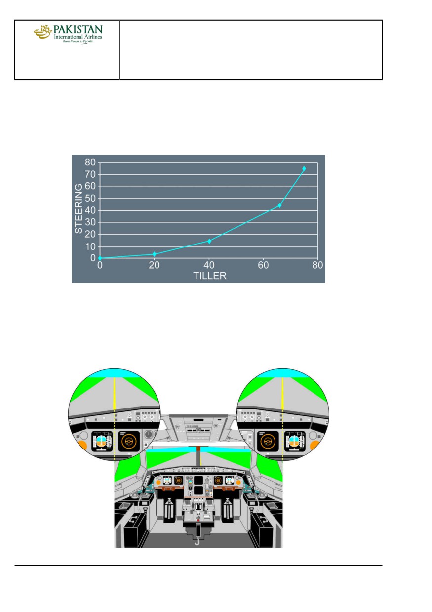
The Nosewheel steering is "by-wire" with no mechanical connection between the tiller and the
nosewheel. The relationship between tiller deflection and nosewheel angle is not linear and the
tiller forces are light.
Tiller Deflection vs. Nosewheel Steering Angle
Therefore, the PF should move the tiller smoothly and maintain the tiller's position. Any correction
should be small and smooth, and maintained for enough time to enable the pilot to assess the
outcome. Being over-active on the tiller will cause uncomfortable oscillations.
On straight taxiways, the aircraft is correctly aligned on the centerline, when the centerline is
lined-up between the PFD and ND.
Proper Centerline Following
PIA A318/A319/A320/A321 FLEET
PR-NP-SOP-100 P 4/10
FCTM
← C →
23 NOV 21
PROCEDURES
NORMAL PROCEDURES
A318/A319/A320/A321
FLIGHT CREW
STANDARD OPERATING PROCEDURES - TAXI
TECHNIQUES MANUAL
If both pilots act on the tiller or pedals, their inputs are added until the maximum value of the
steering angle (programmed within the BSCU) is reached.
When the seating position is correct, the cut-off angle is 20 °, and the visual ground geometry
provides an obscured segment of 42 ft (12.5 m). During taxi, a turn must be initiated before an
obstacle approaches the obscured segment. This provides both wing and tail clearance, with
symmetric thrust and no differential braking.
Asymmetric thrust can be used to initiate a tight turn and to keep the aircraft moving during the
turn. If nosewheel lateral skidding occurs while turning, reduce taxi speed or increase turn radius.
Avoid stopping the aircraft in a turn, because excessive thrust will be required to start the aircraft
moving again.
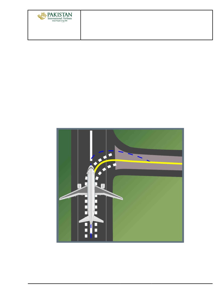
The flight crew should be aware that the main gear on the inside of a turn will always cut the
corner and track inside of the nosewheel track. For this reason, the oversteering technique may be
considered especially for A321 where main gear is 20 m behind the pilot.
Oversteering Technique
When exiting a tight turn, the pilot should anticipate the steer out. Additionally, the pilot should
allow the aircraft to roll forward for a short distance to minimize the stress on the main gears.
In the event that one or more tires is/are deflated on the main landing gear, the maximum
permitted steering angle will be limited by the aircraft speed. Therefore, with one tire deflated, the
PIA A318/A319/A320/A321 FLEET
PR-NP-SOP-100 P 5/10
FCTM
← C →
23 NOV 21
PROCEDURES
NORMAL PROCEDURES
A318/A319/A320/A321
FLIGHT CREW
STANDARD OPERATING PROCEDURES - TAXI
TECHNIQUES MANUAL
aircraft speed is limited to 7 kt and nosewheel steering can be used. With two tires deflated, the
aircraft speed is limited to 3 kt and nosewheel steering angle should be limited to 30 °.
For turns of 90 ° or more, the aircraft speed should be less than 10 kt.
180 DEGREES TURN ON RUNWAY
Ident.: PR-NP-SOP-100-00021675.0001001 / 06 JUN 17
Applicable to: ALL
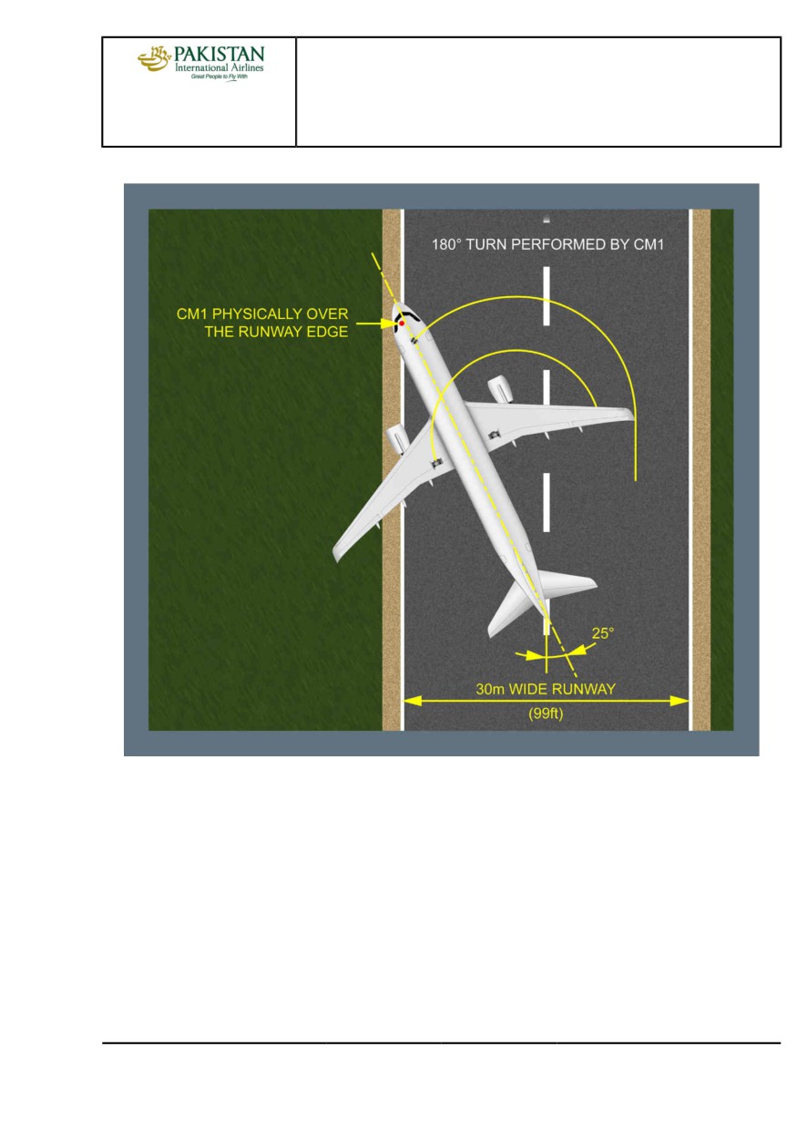
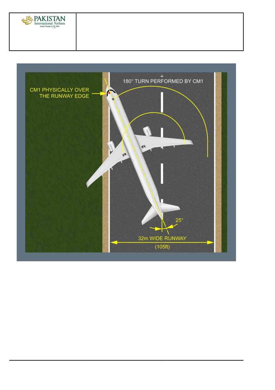
For more information on the minimum runway width that is necessary to perform a 180 ° turn with the
following technique, Refer to FCOM/DSC-20-30 180 degrees Turn on Runway.
Note:
If the runway is wet or contaminated, the aircraft may skid, particularly on painted parts of
the runway. The flight crew should consider additional margin when the runway is wet or
contaminated.
IF THE PF IS THE CREWMEMBER IN THE LEFT HAND SEAT (CM1)
Taxi on the right hand side of the runway.
Maintain a ground speed between 5 kt and 8 kt during the entire maneuver.
Note:
On wet or contaminated runway, it is recommended to maintain a speed of 5 kt during
the entire maneuver.
Turn left, maintaining a 25 ° divergence from the runway axis.
Monitor the approaching runway edge.
When the CM1 is physically over the runway edge:
- Turn right, up to full tiller deflection
- If necessary, use asymmetric thrust (IDLE on ENG 2) and/or differential braking (more brake
pressure on the right side) to maintain a constant speed.
When the 180 ° turn is complete, align with runway centerline and release the tiller to neutral
position before stopping.
PIA A318/A319/A320/A321 FLEET
PR-NP-SOP-100 P 6/10
FCTM
← C to D →
23 NOV 21
PROCEDURES
NORMAL PROCEDURES
A318/A319/A320/A321
FLIGHT CREW
STANDARD OPERATING PROCEDURES - TAXI
TECHNIQUES MANUAL
For A318/A319/A320/A320Neo
PIA A318/A319/A320/A321 FLEET
PR-NP-SOP-100 P 7/10
FCTM
← D →
23 NOV 21
PROCEDURES
NORMAL PROCEDURES
A318/A319/A320/A321
FLIGHT CREW
STANDARD OPERATING PROCEDURES - TAXI
TECHNIQUES MANUAL
For A321
IF THE PF IS THE CREWMEMBER IN THE RIGHT HAND SEAT (CM2)
Note:
the technique is symmetrical
Taxi on the left hand side of the runway.
Maintain a ground speed between 5 kt and 8 kt during the entire maneuver.
Note:
On wet or contaminated runway, it is recommended to maintain a speed of 5 kt during
the entire maneuver.
Turn right, maintaining a 25 ° divergence from the runway axis.
Monitor the approaching runway edge.
PIA A318/A319/A320/A321 FLEET
PR-NP-SOP-100 P 8/10
FCTM
← D →
23 NOV 21
PROCEDURES
NORMAL PROCEDURES
A318/A319/A320/A321
FLIGHT CREW
STANDARD OPERATING PROCEDURES - TAXI
TECHNIQUES MANUAL
When the CM2 is physically over the runway edge:
- Turn left, up to full tiller deflection
- If necessary, use asymmetric thrust (IDLE on ENG 1) and/or differential braking (more brake
pressure on the left side) to maintain a constant speed.
When the 180 ° turn is complete, align with runway centerline and release the tiller to neutral
position before stopping.
LAST DATA CHANGES BEFORE TAKEOFF
Ident.: PR-NP-SOP-100-00021859.0001001 / 05 DEC 17
Applicable to: ALL
If the takeoff conditions change during the taxi phase, and if the previous performance computation
is no longer appropriate, the flight crew must update the takeoff data. This is the case for example in
the following conditions:
- The runway in use changes, or
- The runway condition deteriorates, or
- The use of a new intersection shortens the runway length, or
- The wind or the temperature changes.
In order to ensure that the performance data used for the takeoff is accurate, the technique to
perform this update is the same as for the BEFORE PUSHBACK OR START phase (Refer to
NP-SOP-BEFORE PUSHBACK OR START. However, the tasksharing is different. Both of the
following apply:
- The PF delegates the FMS updates to the PM, in order to limit disruption during taxi
- As a result, the PF must crosscheck the data that the PM modified in the FMS.
In order to compute and crosscheck the performance data, the PF should perform one of the
following:
- Stop the aircraft, or
- Transfer the control to the PM.
DEPARTURE BRIEFING CONFIRMATION
Ident.: PR-NP-SOP-100-00018789.0001001 / 22 NOV 21
Applicable to: ALL
The departure briefing confirmation should only review any changes that may have occurred since
the full departure briefing done at the parking bay (e.g. change of SID, change in runway conditions,
etc.).
PIA A318/A319/A320/A321 FLEET
PR-NP-SOP-100 P 9/10
FCTM
← D to F
23 NOV 21
PROCEDURES
NORMAL PROCEDURES
A318/A319/A320/A321
FLIGHT CREW
STANDARD OPERATING PROCEDURES - TAXI
TECHNIQUES MANUAL
ADIRS ALIGNMENT
Ident.: PR-NP-SOP-100-00020404.0001001 / 20 MAR 17
Applicable to: ALL
During taxi, a good way to check a global consistency of FMGC entries (position and flight plan) is
to check the runway and the SID on the ND in comparison to the aircraft symbol, that indicates the
current aircraft position. To do so, set the ND in ARC or NAV mode with a range 10 NM.
PIA A318/A319/A320/A321 FLEET
PR-NP-SOP-100 P 10/10
FCTM
G
23 NOV 21
PROCEDURES
NORMAL PROCEDURES
A318/A319/A320/A321
FLIGHT CREW
STANDARD OPERATING PROCEDURES - BEFORE TAKEOFF
TECHNIQUES MANUAL
PACKS
Ident.: PR-NP-SOP-110-00016303.0001001 / 20 MAR 17
Applicable to: ALL
If the takeoff has to be achieved without air bleed fed from the engines for performance reasons,
but air conditioning desired, the APU bleed may be used with packs ON, thus maintaining engine
performance level and passenger comfort. In case of APU auto shut down during takeoff, the engine
thrust is frozen till the thrust is manually reduced. The packs revert to engine bleed which causes an
increase of EGT to keep N1/EPR.
If the takeoff is performed with one pack unserviceable, the procedure states to set the failed pack
to OFF. The takeoff may be performed with the other pack ON (if performances permit) with TOGA
or FLEX thrust, the pack being supplied by the onside bleed. In this asymmetric bleed configuration,
the N1 takeoff value is limited to the value corresponding to the bleed ON configuration and takeoff
performance must be computed accordingly.
PIA A318/A319/A320/A321 FLEET
PR-NP-SOP-110 P 1/2
FCTM
A
22 MAR 17
PROCEDURES
NORMAL PROCEDURES
A318/A319/A320/A321
FLIGHT CREW
STANDARD OPERATING PROCEDURES - BEFORE TAKEOFF
TECHNIQUES MANUAL
Intentionally left blank
PIA A318/A319/A320/A321 FLEET
PR-NP-SOP-110 P 2/2
FCTM
22 MAR 17