Airbus A318/319/320/321. FLIGHT CREW TECHNIQUES MANUAL (2005-2022) - page 8
PROCEDURES
NORMAL PROCEDURES
A318/A319/A320/A321
FLIGHT CREW
STANDARD OPERATING PROCEDURES - TAKEOFF
TECHNIQUES MANUAL
THRUST SETTING
Ident.: PR-NP-SOP-120-00018791.0001001 / 16 JAN 18
Applicable to: ALL
The Thrust Setting procedure ensures that all engines will accelerate similarly. If not properly applied,
this may lead to asymmetrical thrust increase, and, consequently, to severe directional control
problem.
If the thrust levers are not set to the proper take-off detent, e.g. FLX instead of TOGA, an alert
triggers on the ECAM.
At any time during FLEX takeoff, the flight crew may set the thrust levers to TOGA.
TAKEOFF ROLL
Ident.: PR-NP-SOP-120-00018792.0001001 / 04 NOV 20
Applicable to: ALL
Once the thrust is set, the PF announces the indications on the FMA. The PM must check that the
thrust is set by 80 kt and must announce "Thrust Set".
The Captain must keep his hand on the thrust levers when the thrust levers are set to TOGA/FLX
notch and until V1.
During the take-off roll, the PM monitors the PFD and ENG indications to ensure early detection and
appropriate decision making in the case of malfunction. By scanning the airspeed indications, the
PM will detect any inconsistent airspeed indications between instruments or absence of airspeed
indications.
On a normal takeoff, to counteract the pitch up moment during thrust application, the PF should apply
half forward or full forward sidestick (depending on wind conditions) at the start of the takeoff roll until
reaching 80 kt. At this point, the input should be gradually reduced to be zero by 100 kt.
The PF should use pedals to keep the aircraft straight. The nosewheel steering authority decreases
at a pre-determined rate as the groundspeed increases (no more efficiency at 130 kt) and the rudder
becomes more effective. The use of the tiller is not recommended during takeoff roll, because of its
high efficiency, which might lead to aircraft overreaction.
For crosswind takeoffs, routine use of into wind aileron is not necessary. In strong crosswind
conditions, small lateral stick input may be used to maintain wings level, if deemed necessary due to
into wind wing reaction, but avoid using large deflections, resulting in excessive spoiler deployment
which increase the aircraft tendency to turn into the wind (due to high weight on wheels on the spoiler
extended side), reduces lift and increases drag. Spoiler deflection becomes significant with more
than a third sidestick deflection.
In the event of unexpected lateral disturbance during takeoff roll, the flight crew should use the
rudder as for counteracting any lateral disturbance. Indeed, excessive rudder input may increase
PIA A318/A319/A320/A321 FLEET
PR-NP-SOP-120 P 1/8
FCTM
A to B →
10 AUG 21
PROCEDURES
NORMAL PROCEDURES
A318/A319/A320/A321
FLIGHT CREW
STANDARD OPERATING PROCEDURES - TAKEOFF
TECHNIQUES MANUAL
the magnitude of the lateral disturbance. The flight crew may be surprised during takeoff roll by
unexpected lateral disturbance in conditions such as:
- The presence of thermals or thermal vortices that often develop in hot and dry countries.
Sometimes, these thermal streams get stronger, and create small whirlwinds referred to as "dust
devils", or
- The jet blast of another aircraft close to the active runway, or
- The wind that accelerates between two buildings by "venturi" effect.
As the aircraft lifts off, any lateral stick input applied will result in a roll rate demand, making aircraft
lateral control more difficult. Wings must be level.
In case of low visibility takeoff, visual cues are primary means to track the runway centerline. The
PFD yaw bar provides an assistance in case of expected fog patches if ILS available.
ROTATION
Ident.: PR-NP-SOP-120-00018793.0001001 / 27 FEB 18
Applicable to: ALL
ROTATION TECHNIQUE
The rotation technique is similar on all fly-by-wire aircraft.
To initiate the rotation, the flight crew performs a positive backward stick input. When the rotation
is initiated, the flight crew achieves a rotation rate of approximately 3 °/s resulting in a continuous
pitch increase.
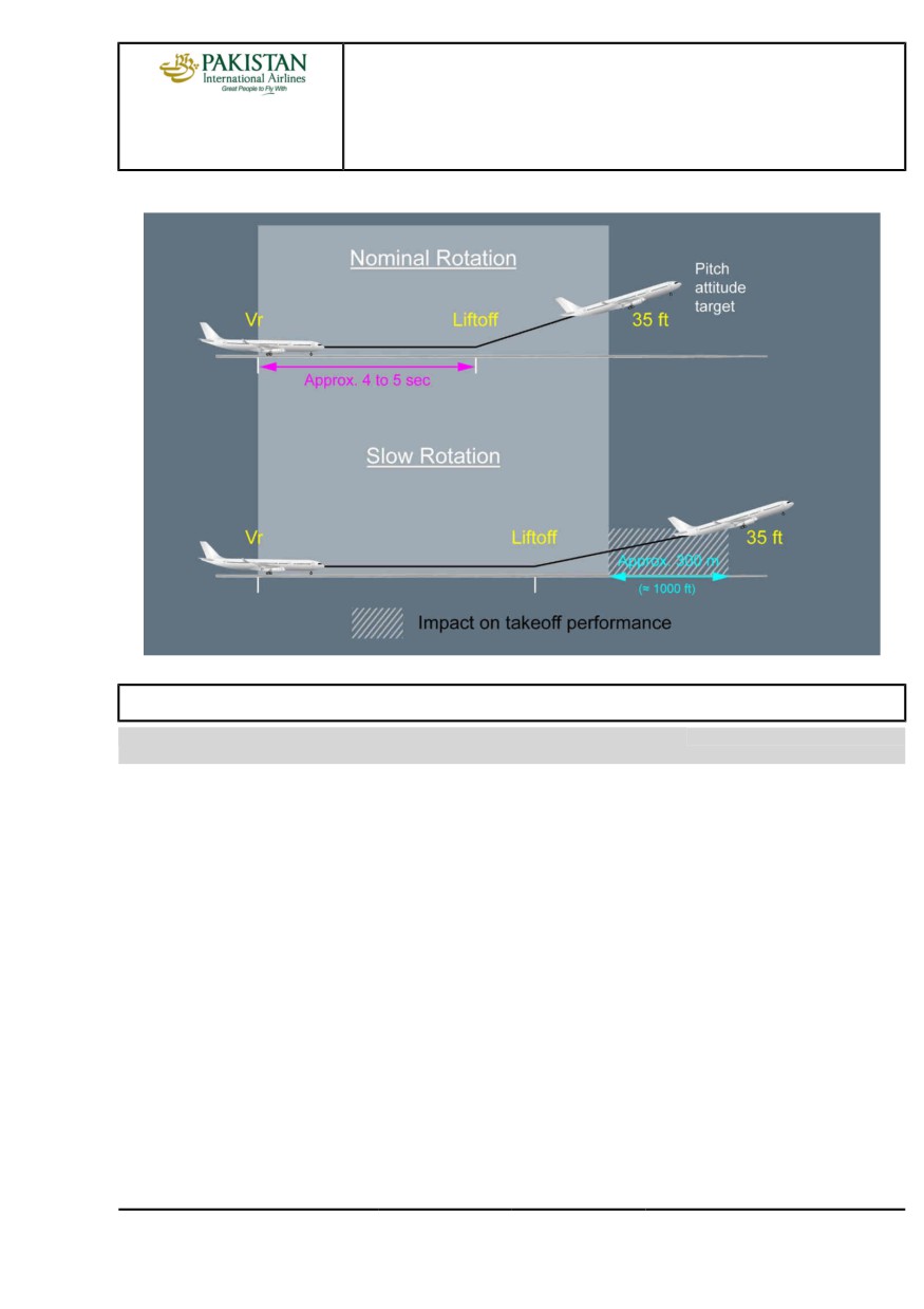
During the rotation, the aircraft liftoff occurs at approximately 10 ° of pitch, typically around 4 to 5 s
after the initiation of the rotation. After the liftoff, the PF targets the required pitch attitude.
To monitor the rotation, the PF uses the outside visual references. Once airborne, the PF controls
the pitch attitude target on the PFD.
A slow rotation rate or an under rotation (below takeoff pitch target) has an impact on takeoff
performance (refer to below graphic):
- The takeoff run and the takeoff distance increase
- The obstacle clearance after takeoff decreases.
PIA A318/A319/A320/A321 FLEET
PR-NP-SOP-120 P 2/8
FCTM
← B to C →
10 AUG 21
PROCEDURES
NORMAL PROCEDURES
A318/A319/A320/A321
FLIGHT CREW
STANDARD OPERATING PROCEDURES - TAKEOFF
TECHNIQUES MANUAL
Performance impacts for a rotation rate of approximately 2 °/s
TAIL STRIKE AVOIDANCE
Ident.: PR-NP-SOP-120-00018798.0001001 / 27 FEB 18
Applicable to: ALL
INTRODUCTION
If tailstrike is not a concern for the A318, the importance of this subject increases as fuselage
length increases. Therefore, it is particularly important for A321 operators.
Tail strikes can cause extensive structural damage, which can jeopardize the flight and lead
to heavy maintenance action. They most often occur in such adverse conditions as crosswind,
turbulence, windshear, etc.
MAIN FACTORS
EARLY ROTATION
Early rotation occurs when rotation is initiated below the scheduled VR. The potential reasons
for this are:
• The calculated VR is incorrect for the aircraft weight or flap configuration.
• The PF commands rotation below VR due to gusts, windshear or an obstacle on the runway.
Whatever the cause of the early rotation, the result will be an increased pitch attitude at liftoff,
and consequently a reduced tail clearance.
PIA A318/A319/A320/A321 FLEET
PR-NP-SOP-120 P 3/8
FCTM
← C to D →
10 AUG 21
PROCEDURES
NORMAL PROCEDURES
A318/A319/A320/A321
FLIGHT CREW
STANDARD OPERATING PROCEDURES - TAKEOFF
TECHNIQUES MANUAL
ROTATION TECHNIQUE
The rotation technique with the associated rotation rate is described in the FCTM
PR-NP-SOP-Takeoff (Refer to PR-NP-SOP-Takeoff-Rotation)
An abrupt increase of rotation rate close to liftoff might lead to a tailstrike.
If the established pitch rate is not satisfactory, the PF must correct it as soon as detected.
CONFIGURATION (NOT APPLICABLE TO A318)
When performance is limiting the takeoff weight, the flight crew uses TOGA thrust and selects
the configuration that provides the highest takeoff weight.
When the actual takeoff weight is lower than the permissible one, the flight crew uses FLEX TO
thrust. For a given aircraft weight, a variety of flap configurations are possible. Usually, the flight
crew selects the configuration that provides the maximum FLEX temperature. This is done to
prolong engine life. The first degrees of flexible thrust have an impact on maintenance costs
about 5 times higher than the last one.
The configuration that provides the maximum FLEX temperature varies with the runway length.
On short runways, CONF 3 usually provides the highest FLEX temperature, and the tail
clearance at lift off does not depends on the configuration.
On medium or long runways, the second segment limitation becomes the limiting factor, and
CONF 2 or CONF 1+F becomes the optimum configuration, in term of FLEX temperature.
In these cases, the tail clearance at lift off depends on the configuration. The highest flap
configuration gives the highest tailstrike margin.
TAKEOFF TRIM SETTING
The main purpose of the pitch trim setting for take-off is to provide consistent rotation
characteristics. Take-off pitch trim is set manually via the pitch trim wheel.
The aircraft performs a safe takeoff, provided the pitch trim setting is within the green band on
the pitch trim wheel.
However, the pitch trim setting significantly affects the aircraft behaviour during rotation:
- With a forward CG and the pitch trim set to the nose-down limit the pilots will feel an aircraft
"heavy to rotate" and aircraft rotation will be very slow in response to the normal take off stick
displacement.
- With an aft CG and the pitch trim set to the nose-up limit the pilots will most probably have to
counteract an early autorotation until VR is reached.
In either case the pilot may have to modify his normal control input in order to achieve the
desired rotation rate, but should be cautious not to overreact.
CROSSWIND TAKEOFF
It is said in the TAKEOFF ROLL paragraph that care should be taken to avoid using large
deflection, resulting in excessive spoiler deployment. A direct effect of the reduction in lift due to
PIA A318/A319/A320/A321 FLEET
PR-NP-SOP-120 P 4/8
FCTM
← D →
10 AUG 21
PROCEDURES
NORMAL PROCEDURES
A318/A319/A320/A321
FLIGHT CREW
STANDARD OPERATING PROCEDURES - TAKEOFF
TECHNIQUES MANUAL
the extension of the spoilers on one wing will be a reduction in tail clearance and an increased
risk of tailstrike.
OLEO INFLATION
The correct extension of the main landing gear shock absorber (and thus the nominal increase
in tail clearance during the rotation) relies on the correct inflation of the oleos.
ACTION IN CASE OF TAILSTRIKE
If a tailstrike occurs at take-off, flight at altitude requiring a pressurized cabin must be avoided and
a return to the originating airport should be performed for damage assessment.
ACCELERATION ALTITUDE
Ident.: PR-NP-SOP-120-00019320.0001001 / 20 MAR 17
Applicable to: ALL
At the acceleration altitude, the FD pitch mode changes from SRS to CLB or OP CLB mode. The
speed target jumps:
• Either to the managed target speed e.g. speed constraint, speed limit or ECON climb speed
• Or to the preselected climb speed (entered by the pilot on the MCDU PERF CLB page before
takeoff).
If green dot speed is higher than the managed target speed (e.g. speed constraint 220 kt) displayed
by the magenta triangle on the PFD speed scale, the AP/FD will guide the aircraft to green dot (as
per the general managed speed guidance rule). If required by ATC, the crew will select the adequate
target speed (below green dot) on the FCU.
During takeoff phase, F and S speeds are the minimum speeds for retracting the surfaces:
• At F speed, the aircraft accelerating (positive speed trend): retract to 1.
• At S speed, the aircraft accelerating (positive speed trend): retract to 0.
If the ENG MODE selector had been selected to IGN START for take-off, the PM should confirm with
the PF when it may be deselected.
SLATS/FLAPS RETRACTION AT HEAVY WEIGHT
Ident.: PR-NP-SOP-120-00018799.0001001 / 20 MAR 17
Applicable to: ALL
If take-off is carried out at heavy weight, two protections may intervene:
- The Automatic Retraction System (ARS)
- The Alpha Lock function
PIA A318/A319/A320/A321 FLEET
PR-NP-SOP-120 P 5/8
FCTM
← D to F →
10 AUG 21
PROCEDURES
NORMAL PROCEDURES
A318/A319/A320/A321
FLIGHT CREW
STANDARD OPERATING PROCEDURES - TAKEOFF
TECHNIQUES MANUAL
THE AUTOMATIC RETRACTION SYSTEM
While in CONF 1+F and IAS reaches 210 kt (VFE CONF1+F is 215 kt or 225 kt on some A321,
Refer to FCOM/LIM-AG-SPD Maximum Flaps/Slats Speeds), the ARS is activated. The ARS
automatically retracts flaps to 0 °. The VFE displayed on the PFD change from VFE CONF1+F to
VFE CONF 1. As the aircraft accelerates above S speed, the flap lever can be selected to 0. If IAS
decreases below VFE CONF1+F, the flaps will not extend back to 1+F.
THE ALPHA LOCK FUNCTION
The slats alpha/speed lock function will prevent slat retraction at high AOA or low speed at the
moment the flap lever is moved from Flaps 1 to Flaps 0. "A. LOCK" pulses above the E/WD Slat
indication. The inhibition is removed and the slats retract when both alpha and speed fall within
normal values. This is a normal situation for take-off at heavy weight. If Alpha lock function is
triggered, the crew will continue the scheduled acceleration, allowing further slats retraction.
OVERSPEED WARNING DURING SLATS/FLAPS TRANSITION
Ident.: PR-NP-SOP-120-00018801.0001001 / 20 MAR 17
Applicable to: ALL
During the Slats/Flaps transition, the flight crew must respect the VMAX displayed on the PFD. The
VMAX value displayed on the PFD speed scale is based on the Slats/Flaps control lever position.
The OVERSPEED WARNING is based on the actual Slats/Flaps surface position. Therefore,
during Slats/Flaps transition, the dynamic acceleration of the airplane may lead to a temporary
OVERSPEED WARNING even if the current speed is out of the red and black strip displayed on the
PFD. In this situation, there are no operational consequences. The flight crew must report any type of
overspeed event.
LOW ALTITUDE LEVEL OFF
Ident.: PR-NP-SOP-120-00018803.0001001 / 20 MAR 17
Applicable to: ALL
If the aircraft is required to level off below the acceleration altitude, ALT* engages and target speed
goes to initial climb speed. The "LVR CLB" message flashes on the FMA. In this case, the crew
should expect a faster than normal acceleration, and be prepared to retract the flaps and slats
promptly.
NOISE ABATEMENT TAKEOFF
Ident.: PR-NP-SOP-120-00018804.0001001 / 20 MAR 17
Applicable to: ALL
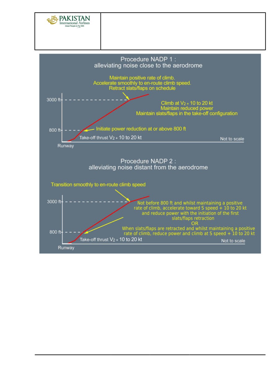
Noise Abatement Procedures will not be conducted in conditions of significant turbulence or
windshear.
PIA A318/A319/A320/A321 FLEET
PR-NP-SOP-120 P 6/8
FCTM
← F to I →
10 AUG 21
PROCEDURES
NORMAL PROCEDURES
A318/A319/A320/A321
FLIGHT CREW
STANDARD OPERATING PROCEDURES - TAKEOFF
TECHNIQUES MANUAL
PIA A318/A319/A320/A321 FLEET
PR-NP-SOP-120 P 7/8
FCTM
← I
10 AUG 21
PROCEDURES
NORMAL PROCEDURES
A318/A319/A320/A321
FLIGHT CREW
STANDARD OPERATING PROCEDURES - TAKEOFF
TECHNIQUES MANUAL
Intentionally left blank
PIA A318/A319/A320/A321 FLEET
PR-NP-SOP-120 P 8/8
FCTM
10 AUG 21
PROCEDURES
NORMAL PROCEDURES
A318/A319/A320/A321
FLIGHT CREW
STANDARD OPERATING PROCEDURES - CLIMB
TECHNIQUES MANUAL
CLIMB MODES
Ident.: PR-NP-SOP-140-00018856.0004001 / 20 MAR 17
Applicable to: ALL
The AP/FD climb modes may be either:
- Managed, or
- Selected.
MANAGED
The managed AP/FD mode in climb is CLB. Its use is recommended as long as the aircraft is
cleared along the F-PLN.
SELECTED
The selected AP/FD modes in climb are OP CLB, V/S and EXPED .
OP CLB is to be used if ATC gives radar vector or clears the aircraft direct to a given FL without
any climb constraints.
In areas of high traffic density, low values of vertical speed will reduce the possibility of nuisance
TCAS warnings.
If the crew selects a high V/S, it may happen that the aircraft is unable to climb with this high V/S
and to maintain the target speed with Max Climb thrust, for performance reasons. In that case,
the AP/FD will guide to the target V/S, and the A/THR will command up to Max Climb thrust, in
order to try to keep the target speed; but the aircraft will decelerate and its speed might reach
VLS. When VLS is reached the AP will pitch the aircraft down so as to fly a V/S, which allows
maintaining VLS. A triple click is generated.
Whenever V/S is used, pilots should pay particular attention to the speed trend as V/S takes
precedence over speed requirements.
The EXPED mode is used to climb with maximum vertical gradient i.e. the target speed
becomes green dot. Its use should be avoided above FL 250.
The crew should be aware that altitude constraints in the MCDU F-PLN page are observed only
when the climb is managed, i.e. when CLB is displayed on the FMA. Any other vertical mode will
disregard any altitude constraints.
A likely scenario would be, when the FCU altitude is set above an altitude constraint and the pilot
selects V/S when below that constraint to avoid a potential TCAS TA. In this case, the aircraft will
disregard the altitude constraint.
PIA A318/A319/A320/A321 FLEET
PR-NP-SOP-140 P 1/4
FCTM
A
02 SEP 20
PROCEDURES
NORMAL PROCEDURES
A318/A319/A320/A321
FLIGHT CREW
STANDARD OPERATING PROCEDURES - CLIMB
TECHNIQUES MANUAL
SMALL ALTITUDE CHANGES
Ident.: PR-NP-SOP-140-00016306.0001001 / 20 MAR 17
Applicable to: ALL
The use of low values of V/S, e.g. less than 1 000 ft/min, may be appropriate for small altitude
changes as it makes the guidance smoother and needs less thrust variation.
SPEED CONSIDERATIONS
Ident.: PR-NP-SOP-140-00018857.0001001 / 20 MAR 17
Applicable to: ALL
The climb speed may be either:
- Managed, or
- Selected.
MANAGED
The managed climb speed, computed by the FMGS, provides the most economical climb profile
as it takes into account weight, actual and predicted winds, ISA deviation and Cost Index (CI). The
managed climb speed also takes into account any speed constraints, e.g. the default speed limit
which is 250 kt up to 10 000 ft.
SELECTED
If necessary, the climb speed can be either pre-selected on ground prior to take-off on the MCDU
PERF CLIMB page or selected on the FCU as required.
On ground, prior take-off, speed target at acceleration altitude can be pre-selected on the MCDU
PERF CLIMB page. It is to be used when the F-PLN has a sharp turn after take-off, when high
angle of climb is required or for ATC clearance compliance.
Once airborne, the speed can be selected on FCU to achieve the maximum rate of climb or the
maximum gradient of climb.
The speed to achieve the maximum rate of climb, i.e. to reach a given altitude in the shortest time,
lies between ECON climb speed and green dot. As there is no indication of this speed on the PFD,
a good rule of thumb is to use turbulence speed to achieve maximum rate.
The speed to achieve the maximum gradient of climb, i.e. to reach a given altitude in a shortest
distance, is green dot. The MCDU PERF CLB page displays the time and distance required to
achieve the selected altitude by climbing at green dot speed. Avoid reducing to green dot at high
altitude, particularly at heavy weight, as it can take a long time to accelerate to ECON mach.
Pilots should be aware that it is possible to select and fly a speed below green dot but there would
be no operational benefit in doing this.
When selected speed is used, the predictions on the F-PLN page assume the selected speed
is kept till the next planned speed modification, e.g. 250 kt /10 000 ft, where managed speed is
supposed to be resumed. Consequently, the FM predictions remain meaningful.
PIA A318/A319/A320/A321 FLEET
PR-NP-SOP-140 P 2/4
FCTM
B to C →
02 SEP 20
PROCEDURES
NORMAL PROCEDURES
A318/A319/A320/A321
FLIGHT CREW
STANDARD OPERATING PROCEDURES - CLIMB
TECHNIQUES MANUAL
When IAS is selected in lower altitude, there is an automatic change to Mach at a specific
crossover altitude.
Finally, as selected speed does not provide the optimum climb profile, it should only be used when
operationally required, e.g. ATC constraint or weather.
VERTICAL PERFORMANCE PREDICTIONS
Ident.: PR-NP-SOP-140-00018858.0001001 / 20 MAR 17
Applicable to: ALL
The MCDU PROG page provides the crew with the MAX REC ALT and with the OPT ALT
information (See cruise section). This information is to be used to rapidly answer to ATC: "CAN YOU
CLIMB TO FL XXX?"
The MCDU PERF CLB page provides predictions to a given FL in terms of time and distance
assuming CLB mode. This FL is defaulted to the FCU target altitude or it may be manually inserted.
The level arrow on the ND assumes the current AP engaged mode. This information is to be used
to rapidly answer to ATC: "CAN YOU MAKE FL XXX by ZZZ waypoint?". The crew will use a PD
(Place/Distance), i.e. ZZZ,-10 waypoint if the question is "CAN YOU MAKE FL XXX , 10 NM before
ZZZ point?"
LATERAL NAVIGATION
Ident.: PR-NP-SOP-140-00018859.0001001 / 20 MAR 17
Applicable to: ALL
If the aircraft is following the programmed SID, the AP/FD should be in NAV. If ATC vectors the
aircraft, HDG will be used until a time when clearance is given to either resume the SID or track
direct to a specific waypoint. In either case, the crew must ensure that the waypoints are properly
sequenced.
The crew should keep in mind that the use of HDG mode e.g. following ATC radar vectors, will revert
CLB to OP CLB and any altitude constraints in the MCDU F-PLN page will not be observed unless
they are selected on the FCU.
UNDUE ACTIVATION OF GO-AROUND PHASE
Ident.: PR-NP-SOP-140-00023997.0001001 / 28 MAY 20
Applicable to: ALL
In some specific cases, the FMS Go-Around phase may be unduly activated. This situation may
be encountered after takeoff if the aircraft is above the ACC ALT and the flight crew sets the thrust
levers to TOGA detent with at least CONF 1.
PIA A318/A319/A320/A321 FLEET
PR-NP-SOP-140 P 3/4
FCTM
← C to F →
02 SEP 20
PROCEDURES
NORMAL PROCEDURES
A318/A319/A320/A321
FLIGHT CREW
STANDARD OPERATING PROCEDURES - CLIMB
TECHNIQUES MANUAL
In such situation, the flight crew should do either of the following in order to activate the CLIMB
phase:
- Insert a NEW DEST (different from the current DEST), or
- Select the ALTN destination.
Once the FMS CLIMB phase is activated again, the flight crew should modify the DEST in order to
insert the DEST of the intended flight.
PIA A318/A319/A320/A321 FLEET
PR-NP-SOP-140 P 4/4
FCTM
← F
02 SEP 20
PROCEDURES
NORMAL PROCEDURES
A318/A319/A320/A321
FLIGHT CREW
STANDARD OPERATING PROCEDURES - CRUISE
TECHNIQUES MANUAL
FMS USE
Applicable to: ALL
Ident.: PR-NP-SOP-150-10-00020458.0001001 / 20 MAR 17
CRUISE FL
If the aircraft is cleared to a lower cruise flight level than the pre-planned cruise flight level
displayed on MCDU PROG page, the cruise Mach number will not be targeted. The crew will
update the MCDU PROG page accordingly.
When at cruise FL, the AP altitude control is soft. This means that the AP will allow small altitude
variation around the cruise altitude (typically ± 50 ft) to keep cruise Mach before a readjustment of
thrust occurs. This optimizes the fuel consumption in cruise.
Ident.: PR-NP-SOP-150-10-00020457.0001001 / 20 MAR 17
WIND AND TEMPERATURE
When reaching cruise FL, the crew will ensure that the wind and temperatures are correctly
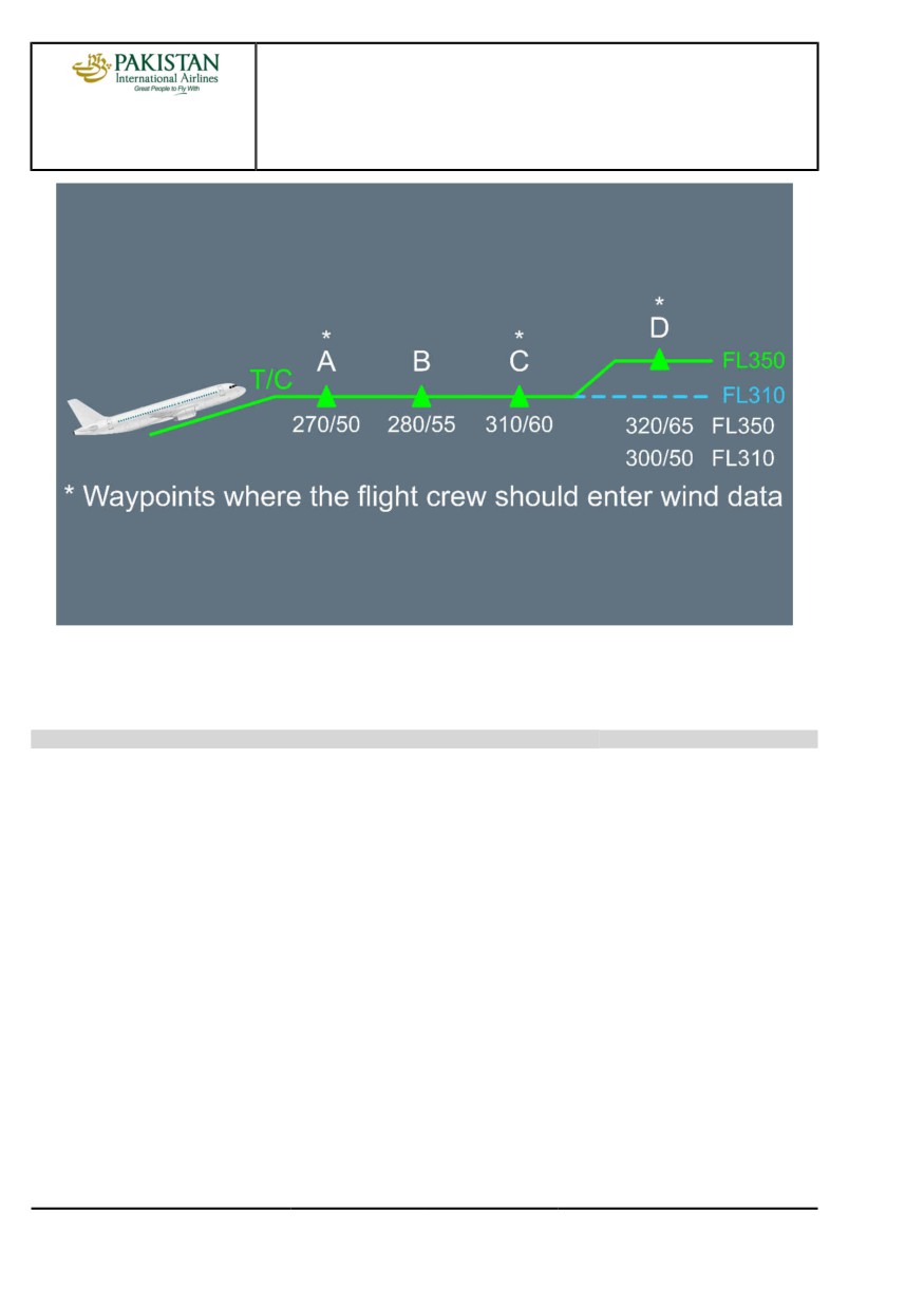
entered and the lateral and vertical F-PLN reflect the CFP. Wind entries should be made at
waypoints when there is a difference of either 30 ° or 30 kt for the wind data and 5 °C for
temperature deviation. This will ensure that the FMS fuel and time predictions are as accurate as
possible.
Ident.: PR-NP-SOP-150-10-00018860.0002001 / 20 MAR 17
STEP CLIMB
If there is a STEP in the F-PLN, the crew will ensure that the wind is properly set at the first
waypoint beyond the step (D on the following example) at both initial FL and step FL.
PIA A318/A319/A320/A321 FLEET
PR-NP-SOP-150 P 1/10
FCTM
A →
23 NOV 21
PROCEDURES
NORMAL PROCEDURES
A318/A319/A320/A321
FLIGHT CREW
STANDARD OPERATING PROCEDURES - CRUISE
TECHNIQUES MANUAL
If at D waypoint, the CFP provides the wind at FL 350 but not at FL 310, it is recommended to
insert the same wind at FL 310 as the one at FL 350. This is due to wind propagation rules, which
might affect the optimum FL computation.
Ident.: PR-NP-SOP-150-10-00020455.0002001 / 20 MAR 17
ETP
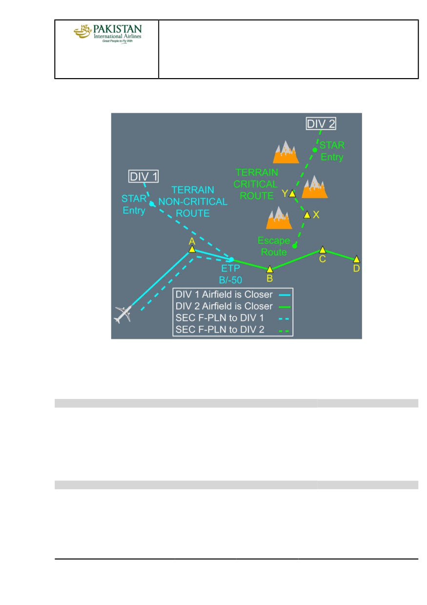
ETP function should be used to assist the crew in making a decision should an en-route diversion
be required. Suitable airport pairs should be entered on the ETP page and the FMS will then
calculate the ETP. Each time an ETP is sequenced, the crew should insert the next suitable
diversion airfield.
The SEC F-PLN is a useful tool and should be used practically. The ETP should be inserted in the
SEC F-PLN as a PD (Place/Distance) and the route to diversion airfield should be finalized. By
programming a potential en-route diversion, the crew would reduce their workload should a failure
occur. This is particularly true when terrain considerations apply to the intended diversion route.
When an ETP is sequenced, the crew will:
- Access the ETP page
- Insert the next applicable diversion airfield with associated wind
- Read new ETP
- Insert new ETP as a PD
PIA A318/A319/A320/A321 FLEET
PR-NP-SOP-150 P 2/10
FCTM
← A →
23 NOV 21
PROCEDURES
NORMAL PROCEDURES
A318/A319/A320/A321
FLIGHT CREW
STANDARD OPERATING PROCEDURES - CRUISE
TECHNIQUES MANUAL
- Copy active on the SEC F-PLN
- Insert the new diversion as New Dest in the SEC F-PLN from new ETP.
The DATA/Stored Routes function in the MCDU can be used to store up to five possible diversion
routes. These routes can be entered into the SEC F-PLN using the SEC INIT prompt. This prompt
will only be available if the SEC F-PLN is deleted. Refer to FCOM/DSC-22_20-60-30 Using the
Secondary Flight Plan Function for further information.
Ident.: PR-NP-SOP-150-10-00020454.0002001 / 20 MAR 17
CLOSEST AIRPORT
For diversion purpose, the crew can also use the CLOSEST AIRPORT page which provides
valuable fuel/time estimates to the four closest airports from the aircraft position, as well as to
an airport the crew may define. The fuel and time predictions are a function of the average wind
between the aircraft and the airport.
Ident.: PR-NP-SOP-150-10-00020456.0002001 / 20 MAR 17
MISCELLANEOUS
If ATC requires a position report, the crew will use the REPORT page which can be accessed from
PROG page.
PIA A318/A319/A320/A321 FLEET
PR-NP-SOP-150 P 3/10
FCTM
← A →
23 NOV 21
PROCEDURES
NORMAL PROCEDURES
A318/A319/A320/A321
FLIGHT CREW
STANDARD OPERATING PROCEDURES - CRUISE
TECHNIQUES MANUAL
If ATC requires a report on a given radial, the crew will use the FIX INFO page or RADIAL FIX
INFO page which can be accessed from a lateral revision on F-PLN page at PPOS.
If ATC requires a report at a given time, the crew will insert a time marker pseudo waypoint.
If ATC gives a DIR TO clearance to a waypoint far from present position, the crew will use the
ABEAM facility. This facility allows both a better crew orientation and the previously entered winds
to be still considered.
COST INDEX
Ident.: PR-NP-SOP-150-00018861.0001001 / 20 MAR 17
Applicable to: ALL
The Cost Index (CI) is used to take into account the relationship between fuel and time related
costs in order to minimize the trip cost. The CI is calculated by the airline for each sector. From an
operational point of view, the CI affects the speeds (ECON SPEED/MACH) and cruise altitude (OPT
ALT). CI=0 corresponds to maximum range whereas the CI=999 corresponds to minimum time.
The CI is a strategic parameter which applies to the whole flight. However, the CI can be modified
by the crew in flight for valid strategic operational reasons. For example, if the crew needs to reduce
the speed for the entire flight to comply with curfew requirements or fuel management requirements
(XTRA gets close to 0), then it is appropriate to reduce the CI.
The SEC F-PLN can be used to check the predictions associated with new CI. If they are
satisfactory, the crew will then modify the CI in the primary F-PLN. However, the crew should be
aware that any modification of the CI would affect trip cost.
SPEED CONSIDERATIONS
Ident.: PR-NP-SOP-150-00018862.0002001 / 20 MAR 17
Applicable to: ALL
The cruise speed may be either:
- Managed, or
- Selected.
MANAGED
When the cruise altitude is reached, the A/THR operates in SPEED/MACH mode. The optimum
cruise Mach number is automatically targeted. Its value depends on:
- CI
- Cruise flight level
- Temperature deviation
- Weight
- Headwind component.
PIA A318/A319/A320/A321 FLEET
PR-NP-SOP-150 P 4/10
FCTM
← A to C →
23 NOV 21
PROCEDURES
NORMAL PROCEDURES
A318/A319/A320/A321
FLIGHT CREW
STANDARD OPERATING PROCEDURES - CRUISE
TECHNIQUES MANUAL
The crew should be aware that the optimum Mach number will vary according to the above
mentioned parameters, e.g. it will increase with an increasing headwind, e.g. +50 kt head wind
equates to M +0.01.
Should ATC require a specific time over a waypoint, the crew can perform a vertical revision
on that waypoint and enter a time constraint. The managed Mach number would be modified
accordingly to achieve this constraint. If the constraint can be met within a tolerance, a magenta
asterix will be displayed on the MCDU; if the constraint cannot be met, an amber asterix will be
displayed. Once the constrained waypoint is sequenced, the ECON Mach is resumed.
SELECTED
Should ATC require a specific cruise speed or turbulence penetration is required, the pilot must
select the cruise speed on the FCU. FMS predictions are updated accordingly until reaching
either the next step climb or top of descent, where the programmed speeds apply again. The FMS
predictions are therefore realistic.
At high altitude, the speed should not be reduced below GREEN DOT as this may create a
situation where it is impossible to maintain speed and/or altitude as the increased drag may
exceed the available thrust.
SPEED DECAY DURING CRUISE
Ident.: PR-NP-SOP-150-00018863.0001001 / 25 JUL 17
Applicable to: ALL
FACTORS THAT CAUSE A SPEED DECAY DURING CRUISE
On aircraft with no failure, and the A/THR engaged or the MAX CLB Thrust applied in manual
mode, a continuous speed decay during cruise phase may be due to:
- A large and continuous increase in tailwind or decrease in headwind, in addition to an increase
in the Outside Air Temperature (OAT), that results in a decrease of the REC MAX FL (Refer to
PR-NP-SOP-150 Altitude Considerations), or
- A large downdraft, when the flight crew flies (parallel and) downwind in a mountainous area,
due to orographic waves. The downdraft may have a negative vertical speed of more than
500 ft/min. Therefore, if the aircraft is in a downdraft, the flight crew must climb in order to
maintain altitude, and the pitch angle and the thrust value increase. Without sufficient thrust
margin, the flight crew may notice that aircraft speed decays, but the REC MAX FL is not
modified.
THRUST MARGIN AND EXTERNAL PARAMETERS
The flight crew must be aware that at high altitude, the thrust margin (difference between the thrust
in use and the maximum available thrust) is limited. The maximum available thrust decreases
when there is an increase in altitude and/or outside temperature. In some conditions, MCT may be
PIA A318/A319/A320/A321 FLEET
PR-NP-SOP-150 P 5/10
FCTM
← C to D →
23 NOV 21
PROCEDURES
NORMAL PROCEDURES
A318/A319/A320/A321
FLIGHT CREW
STANDARD OPERATING PROCEDURES - CRUISE
TECHNIQUES MANUAL
the maximum available thrust. In such a situation, it is useless to put the thrust levers in the TOGA
detent to try to increase the thrust.
The REC MAX FL indicated in the PROG page of the MCDU decreases when the OAT increases.
The nearer the aircraft is to the REC MAX FL, the smaller the thrust margin.
GREEN DOT (GD) SPEED AS A REFERENCE
The optimum lift/drag speed is the GD speed. The GD speed uses the lowest quantity of thrust
necessary to maintain the required/desired altitude. When the aircraft speed is below GD speed,
any decrease in speed requires an increase in thrust in order to maintain the required/desired
altitude. Therefore, if aircraft speed is below GD speed and continues to decrease, even with the
maximum available thrust in use, if the flight crew maintains the current altitude, the angle of attack
will further increase.
OPERATIONAL RECOMMENDATION
The nearer the aircraft is to the REC MAX FL, the smaller the thrust margin the flight crew has to
manage a speed decay during cruise.
If aircraft speed goes below GD speed, with the maximum available thrust in use, the only way for
the flight crew to avoid a dangerous increase in the angle of attack is to descend.
As a result, the flight crew can recover normal aircraft speed and the normal thrust margin.
ALTITUDE CONSIDERATIONS
Ident.: PR-NP-SOP-150-00018864.0001001 / 20 MAR 17
Applicable to: ALL
The MCDU PROG page displays:
- REC MAX FL
- OPT FL.
REC MAX FL
REC MAX FL reflects the present engine and wing performance and does not take into account
the cost aspect. It provides a 0.3 gbuffet margin. If the crew inserts a FL higher than REC MAX
into the MCDU, it will be accepted only if it provides a buffet margin greater than 0.2 g. Otherwise,
it will be rejected and the message "CRZ ABOVE MAX FL" will appear on the MCDU scratchpad.
This message may also be triggered in case of temperature increase leading the aircraft to fly
above the REC MAX FL. Unless there are overriding operational considerations, e.g. either to
accept a cruise FL higher than REC MAX or to be held significantly lower for a long period, REC
MAX should be considered as the upper cruise limit.
OPT FL
OPT FL displayed on the MCDU is the cruise altitude for minimum cost when ECON MACH is
flown and should be followed whenever possible. It is important to note that the OPT FL displayed
PIA A318/A319/A320/A321 FLEET
PR-NP-SOP-150 P 6/10
FCTM
← D to E →
23 NOV 21
PROCEDURES
NORMAL PROCEDURES
A318/A319/A320/A321
FLIGHT CREW
STANDARD OPERATING PROCEDURES - CRUISE
TECHNIQUES MANUAL
on the PROG page is meaningful only if the wind and temperature profile has been accurately
entered. The flight crew should be aware that flying at a FL different from the OPT FL can have an
adverse effect on the trip cost.
For each Mach number, there will be a different OPT FL. Should an FMGS failure occur, the crew
should refer to the FCOM or QRH to determine the OPT FL. FCOM and QRH charts are only
provided for two different Mach numbers.
STEP CLIMB
Ident.: PR-NP-SOP-150-00018865.0001001 / 15 NOV 21
Applicable to: ALL
From a cost point of view, it is better to climb to a higher cruise altitude when aircraft weight permits,
because the optimum altitude increases when fuel is consumed during the flight. This technique is
referred to as a Step Climb.
The flight crew can plan the step climbs at waypoints, or the FMS can compute the optimum step
points. In order to determine the optimum location of the next FL change, the flight crew uses the
OPTIMUM STEP POINT function on the MCDU STEP ALTS page which is either accessed from
the MCDU F-PLN/VERT REV page or the MCDU PERF CRZ page. If predictions are satisfactory in
terms of time and fuel saving, the flight crew inserts the optimum step point in the temporary flight
plan provided it is compatible with the ATC. The inserted step climb is set as a geographic waypoint.
The flight crew can update the step point by pressing the UPDATE* button on the STEP ALTS page.
The OPT STEP computation is accurate if the flight crew accurately entered the vertical wind profile.
For more information, Refer to FMS Use.
It can be advantageous to request an initial cruise altitude above the OPT FL, if altitude changes
are difficult to obtain on specific routes. This minimizes the possibility of being held at a low altitude
and in high fuel consumption condition for long periods of time. The flight crew should compare the
requested/cleared cruise altitude to the REC MAX FL. Before the flight crew accepts an altitude
above the OPT FL, they should determine if this FL will remain acceptable considering the projected
flight conditions such as turbulence, standing waves or temperature changes.
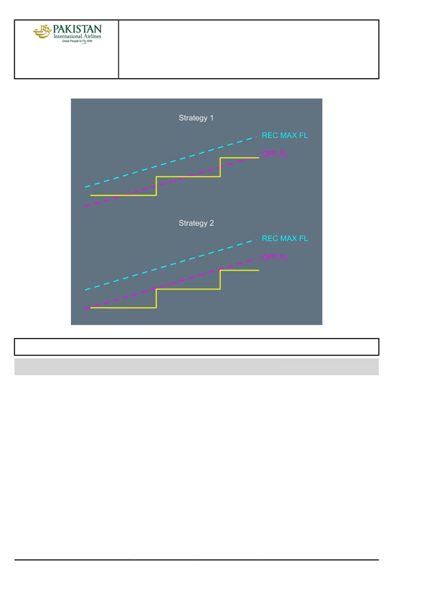
The following graph indicates the two step climb strategies with respect to the OPT FL and the REC
MAX FL. Strategy 1 provides the best trip cost.
PIA A318/A319/A320/A321 FLEET
PR-NP-SOP-150 P 7/10
FCTM
← E to F →
23 NOV 21
PROCEDURES
NORMAL PROCEDURES
A318/A319/A320/A321
FLIGHT CREW
STANDARD OPERATING PROCEDURES - CRUISE
TECHNIQUES MANUAL
OPT FL Follow Up
FUEL TEMPERATURE
Ident.: PR-NP-SOP-150-00018866.0001001 / 22 MAR 17
Applicable to: ALL
Fuel freeze refers to the formation of wax crystals suspended in the fuel, which can accumulate when
fuel temperature is below the freeze point (-47 °C for jet A1) and can prevent proper fuel feed to the
engines.
During normal operations, fuel temperature rarely decreases to the point that it becomes limiting.
However, extended cruise operations increase the potential for fuel temperatures to reach the freeze
point. Fuel temperature will slowly reduce towards TAT. The rate of cooling of fuel can be expected
to be in the order of 3 °C per hour with a maximum of 12 °C per hour in the most extreme conditions.
PIA A318/A319/A320/A321 FLEET
PR-NP-SOP-150 P 8/10
FCTM
← F to G →
23 NOV 21
PROCEDURES
NORMAL PROCEDURES
A318/A319/A320/A321
FLIGHT CREW
STANDARD OPERATING PROCEDURES - CRUISE
TECHNIQUES MANUAL
If fuel temperature approaches the minimum allowed, the ECAM outputs a caution. Consideration
should be given to achieving a higher TAT:
• Descending or diverting to a warmer air mass may be considered. Below the tropopause, a
4 000 ft descent gives a 7 °C increase in TAT. In severe cases, a descent to as low as 25 000 ft
may be required.
• Increasing Mach number will also increase TAT. An increase of M 0.01 produces approximately
0.7 °C increase in TAT.
In either case, up to 1 h may be required for fuel temperature to stabilise. The crew should consider
the fuel penalty associated with either of these actions.
PIA A318/A319/A320/A321 FLEET
PR-NP-SOP-150 P 9/10
FCTM
← G
23 NOV 21
PROCEDURES
NORMAL PROCEDURES
A318/A319/A320/A321
FLIGHT CREW
STANDARD OPERATING PROCEDURES - CRUISE
TECHNIQUES MANUAL
Intentionally left blank
PIA A318/A319/A320/A321 FLEET
PR-NP-SOP-150 P 10/10
FCTM
23 NOV 21
PROCEDURES
NORMAL PROCEDURES
A318/A319/A320/A321
FLIGHT CREW
STANDARD OPERATING PROCEDURES - DESCENT PREPARATION
TECHNIQUES MANUAL
LANDING PERFORMANCE
Ident.: PR-NP-SOP-160-00022701.0001001 / 15 NOV 21
Applicable to: ALL
GENERAL
DISPATCH POLICY
Airbus recommends to crosscheck at dispatch, in addition to the regulatory performance
requirements, that in the forecast conditions, the FLD for the planned mass is less than the
available runway length (LDA). This check should be made for both the destination and the
destination alternates.
LANDING PERFORMANCE AT TIME OF ARRIVAL
As part of their approach preparation, the flight crew should always make an in-flight
performance calculation, each time conditions have changed from the assumptions made at
dispatch:
- Runway change
If the runway, planned to be used at time of dispatch, is not known, consider that it was
based on the longest runway and no wind. If the runway to be used is shorter, a specific
computation is recommended
- Diversion
- The intended use of autobrake or autoland (as the RLD only considers manual braking)
- The intended use of REV IDLE
- Degradation of the runway conditions since dispatch
- In-flight failure affecting the landing performance.
In the case of degradation of the runway conditions since dispatch, the flight crew should
use all available information that is reported to them, to make an appropriate assessment of
the Runway Surface Conditions. This includes an assessment of how these conditions may
degrade before it is no longer possible to stop the aircraft within the declared distances. If the
flight crew is not sure, they should request to change the runway for a more favorable one, or
decide that a diversion may be a better option.
In order to assess the landing performance, the flight crew should follow the two main steps
described below:
1. Identify the Braking Performance Level with the RCAM for RWY COND selection in the LDG
PERF application
2. Calculate the Landing Performance with the LDG PERF application. Consider a margin of
15 % (Factored In-Flight Landing Distance), except in the case of an emergency.
PIA A318/A319/A320/A321 FLEET
PR-NP-SOP-160 P 1/10
FCTM
A →
23 NOV 21
PROCEDURES
NORMAL PROCEDURES
A318/A319/A320/A321
FLIGHT CREW
STANDARD OPERATING PROCEDURES - DESCENT PREPARATION
TECHNIQUES MANUAL
USE OF REVERSE THRUST
Operational Landing Distances should be calculated in accordance with the planned operation.
For example, if the flight crew expects to use idle reverse thrust only, they should establish the
FLD without reverse thrust.
When the runway is wet or contaminated, Airbus recommends the use of maximum reverse
thrust.
Exceptionally, the flight crew may use idle reverse in wet conditions, when it is ensured that a
safe stop with spoilers and wheel braking alone can be made on a runway contaminated with
standing water. The LDA should therefore exceed the unfactored LD without reverse for the
braking action corresponding to standing water (RWYCC 2, Braking Action Medium to Poor).
USE OF AUTOBRAKE
To avoid landing with unduly high autobrake settings, the FLD with autobrake may exceed the
LDA as long as all of the following conditions are satisfied:
- The RWYCC is 5 or 6
- The LD with autobrake is less than the LDA
- The FLD with maximum manual braking is less than the LDA.
USE OF THE RUNWAY CONDITION ASSESSMENT MATRIX (RCAM)
RUNWAY CONDITION REPORTING
When information in accordance with the GRF SNOWTAM format is available, the flight crew
may use it for the performance assessment.
When information is provided in the non-GRF SNOWTAM format, or any other local format,
the flight crew should use the RCAM to determine the appropriate input parameters for the
performance computation. The non-GRF SNOWTAM format can be detected by its use of field
codes as, for example, F), G).
RCAM LOCATION
Refer to FCOM/EFB-LDG-30 Runway Condition Assessment Matrix for Landing.
INFORMATION PROVIDED BY THE RCAM
The purpose of the RCAM is to provide the flight crew with an identification method of an
appropriate Braking Performance Level, if it is not provided by the airport.
The RCAM provides 6 Braking Performance Levels:
-
6 - Dry
-
5 - Good
-
4 - Good to Medium
-
3 - Medium
PIA A318/A319/A320/A321 FLEET
PR-NP-SOP-160 P 2/10
FCTM
← A →
23 NOV 21
PROCEDURES
NORMAL PROCEDURES
A318/A319/A320/A321
FLIGHT CREW
STANDARD OPERATING PROCEDURES - DESCENT PREPARATION
TECHNIQUES MANUAL
-
2 - Medium to Poor
-
1 - Poor
USE OF THE RCAM
The flight crew gathers all available information (e.g. ATIS, METAR, SNOWTAM, TAF, AIREP,
NOTAM, Airport Documentation) related to Runway Surface Conditions.
The flight crew makes a primary assessment based on Runway Condition information (i.e.
runway state, contaminant type, depth, temperature). This results in a primary Braking
Performance Level.
Then, the flight crew downgrades this primary Braking Performance Level, if:
- A Special AIREP is available and this AIREP corresponds to a lower Braking Performance
Level
- A SNOWTAM includes a lower RWYCC, or the ESF corresponds to a lower Braking
Performance Level
For loose contaminants (Dry Snow, Wet Snow or Slush), the flight crew should not consider
an ESF based on friction measurements
- Complementary information is available and is related to a possible degradation of the
Runway Condition or braking action.
In any case, the flight crew must not use an AIREP, ESF or any other complementary
information to upgrade a primary Braking Performance Level that was based on Runway
Condition information. The flight crew may accept an upgraded RWYCC reported by the airport.
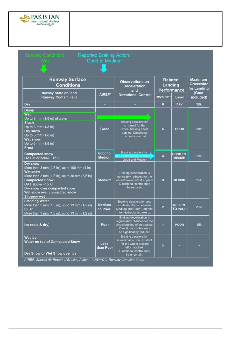
In the following example, the reported Runway Condition is wet, and the AIREP is "Good to
Medium":
1. The primary assessment based on Runway Condition information results in "5 - Good"
2. The downgrade based on Reported Braking Action results in "4 - Good to Medium".
PIA A318/A319/A320/A321 FLEET
PR-NP-SOP-160 P 3/10
FCTM
← A →
23 NOV 21
PROCEDURES
NORMAL PROCEDURES
A318/A319/A320/A321
FLIGHT CREW
STANDARD OPERATING PROCEDURES - DESCENT PREPARATION
TECHNIQUES MANUAL
The following example illustrates the downgrade based on complementary information related to
a possible degradation of the Runway Condition or braking action:
- Runway state reported as wet
- NOTAM “SLIPPERY WHEN WET".
In this example, the flight crew should perform the landing performance assessment with the
Braking Performance Level “3 - Medium”.
PIA A318/A319/A320/A321 FLEET
PR-NP-SOP-160 P 4/10
FCTM
← A →
23 NOV 21
PROCEDURES
NORMAL PROCEDURES
A318/A319/A320/A321
FLIGHT CREW
STANDARD OPERATING PROCEDURES - DESCENT PREPARATION
TECHNIQUES MANUAL
In normal operations, the flight crew should perform the landing performance assessment with
the Braking Performance Level “3 - Medium” if:
- There is rain on the runway
- A NOTAM "SLIPPERY WHEN WET" or the equivalent information (e.g. airport
documentation) warns that the runway braking action is less than when the runway is “WET”.
Note:
Based on current knowledge, hail on the runway cannot be categorized in terms
of its effect on braking performance. Operations on hail covered surfaces are not
recommended due to the risk of engine ingestion and airframe damage.
CROSSWIND
If the flight crew downgrades the braking performance assessment after they consider additional
information, they should also downgrade the maximum crosswind value.
For Maximum Crosswinds, Refer to FCOM/LIM-AG-OPS Crosswind for Takeoff and Landing.
The LDG PERF application automatically takes into account the crosswind limitations according
to the Operator policy.
In the case of strong or gusty crosswind above 20 kt, VAPP should be at least VLS +5 kt; the
5 kt increment above VLS may be increased up to 15 kt at the flight crew's discretion.
RISK OF DEGRADED RUNWAY CONDITIONS
If meteorological conditions may change, or under active precipitation, the flight crew should
consider a backup assessment of the in-flight landing performance. This assessment should
take into account the worst probable Braking Performance Level.
The flight crew may become aware of these conditions late in approach (e.g. following an
AIREP transmission that contains "Medium to Poor", or following the visual assessment of the
runway).
In addition to the usual assessment with the Braking Performance Level "5 - Good", it is safe
practice to perform a second assessment with "2 - Medium to Poor". If the result of the second
assessment shows that the runway is too short, it enables the flight crew to anticipate, in the
event of degraded runway conditions (e.g. heavy rain), an appropriate decision to continue or
not the approach.
SPECIALLY PREPARED WINTER RUNWAY
An airport may be authorized by its national authorities to report a Specially Prepared
Winter Runway combined with a RWYCC of up to 4. This approval depends on a statistical
demonstration based on aircraft data recorded and analyzed for observed braking action. When
this type of report is applicable, the flight crew may consider a RWYCC of 4, if permitted by the
operator policy.
PIA A318/A319/A320/A321 FLEET
PR-NP-SOP-160 P 5/10
FCTM
← A →
23 NOV 21
PROCEDURES
NORMAL PROCEDURES
A318/A319/A320/A321
FLIGHT CREW
STANDARD OPERATING PROCEDURES - DESCENT PREPARATION
TECHNIQUES MANUAL
REPORTED FRICTION
Estimated surface friction should not be reported as it is not possible to establish a correlation
between the values provided by the ground equipment and the aircraft performance. However,
some countries continue to report measured friction. The flight crew should disregard this
information, when available.
DOWNGRADED OR UPGRADED RWYCC
An airport may report a RWYCC that is less than the one associated with the reported
contamination condition according to the RCAM. The runway inspector must consider all the
information available to make the most appropriate report of runway conditions. The information
may include, for example, friction measurements, vehicle control during inspection or local
knowledge. The airport can downgrade any RWYCC to any lower RWYCC. It should not report
any RWYCC 0, as in that case, the runway must be closed.
In some situations, the airport may report a better RWYCC than the primary one obtained from
the RCAM. Upgrades are permitted only when:
- The runway condition results in an RWYCC of 1 or 0 according to the RCAM
- All observations indicate that the braking action is of the order of Good, including friction
measurements.
The maximum upgraded RWYCC is 3.
The flight crew should never upgrade an RWYCC on their own initiative.
DIFFERENT RWYCC ON DIFFERENT THIRDS
The airport may report a different RWYCC for different subsections of the runway that
correspond to a third of the runway length. The flight crew should use the worst RWYCC for the
landing performance assessment, unless a specific operator policy applies.
The flight crew should use the lowest RWYCC to determine the maximum acceptable
crosswind, as even short sections of very slippery conditions can induce a loss of control.
LAYERED CONTAMINATION
The RCAM includes some cases of layered contamination.
The performance section of the SNOWTAM can contain only these cases, for which the effect
on aircraft braking performance is known in terms of RWYCC.
The free text section of the SNOWTAM may report different cases. Most combinations not listed
in the RCAM result in conditions that are too slippery for safe operations.
Depths reported for layered contaminants apply to the top layer only. The flight crew may ignore
loose snow of less than 3 mm (1/8 in) on top of compacted snow.
Any depth of water, snow or slush on top of ice will cause a very slippery condition.
PIA A318/A319/A320/A321 FLEET
PR-NP-SOP-160 P 6/10
FCTM
← A →
23 NOV 21
PROCEDURES
NORMAL PROCEDURES
A318/A319/A320/A321
FLIGHT CREW
STANDARD OPERATING PROCEDURES - DESCENT PREPARATION
TECHNIQUES MANUAL
AIREP OF BRAKING ACTION
Local regulation may require that the flight crew makes AIREPs of observed braking action if
they consider it to be less than previously reported. The RCAM provides the terminology to
be used for these reports (from Good, Good to Medium to Poor or Less Than Poor). It also
provides the associated description of the observation in terms of deceleration capability and
directional control.
Flight crew may find braking action difficult to evaluate, as it is supposed to quantify only the
wheel braking component of the deceleration. Aerodynamic braking and reverse thrust can,
at high speed, permit to achieve the expected deceleration and hide a low wheel braking
efficiency.
The BACF, if installed, may assist the flight crew to make reports (Refer to
FCOM/DSC-46-10-40-30 BRAKING ACTION).
ATC may communicate AIREPs from previous aircraft. Flight crew should take into account the
type of aircraft (weight, approach speed, wheel track) that made the report when they evaluate
the impact on their own landing performance calculations.
EXAMPLES OF LANDING PERFORMANCE CODE - LEVEL ASSESSMENT
RUNWAY CONTAMINATED BY COMPACTED SNOW, OAT -10 °C
Compacted Snow at or below -15 °C is in the category of Good to Medium.
Compacted Snow above -15 °C it is in the category of Medium.
This information indicates that the computation should be done with the Landing Performance
level 3 - Medium and the corresponding maximum crosswind must be taken into account.
RUNWAY COVERED BY LESS THAN 3 MM (1/8 IN) OF WATER BUT HEAVY RAIN WITH
STORM CELLS IN THE VICINITY ARE REPORTED
According to the matrix, the expected landing performance on a runway covered by less than
3 mm (1/8 in) of water (runway is wet) is 5 - Good.
However, heavy rain can saturate the draining capabilities of the runway and result in standing
water. Standing water (more than 3 mm - 1/8 in of water) is in the category of 2 - Medium to
Poor.
This information indicates that it may be appropriate to consider 2 - Medium to Poor Landing
Performance and the corresponding maximum crosswind must be taken into account.
The flight crew should not apply the benefit of runway grooving or PFC in conditions of heavy
rain or storm cells in the vicinity.
RUNWAY COVERED BY TREATED ICE (COLD AND DRY) WITH AN ESTIMATED SURFACE
FRICTION GOOD OR RUNWAY CONDITION CODE 3
Icy runways are in the category of 1 - Poor or 0 - Less than Poor.
PIA A318/A319/A320/A321 FLEET
PR-NP-SOP-160 P 7/10
FCTM
← A →
23 NOV 21
PROCEDURES
NORMAL PROCEDURES
A318/A319/A320/A321
FLIGHT CREW
STANDARD OPERATING PROCEDURES - DESCENT PREPARATION
TECHNIQUES MANUAL
The RCAM does not permit unconditional benefit of runway treatment as, for example, sand,
gravel or chemicals. The success of the surface treatment must be validated by friction
measurements and supported by all other observations of trained airport personnel. The airport
will report an RWYCC 3.
The upgrade of the landing performance may only be performed by the airport. If on treated cold
and dry ice, a surface friction Good or better is measured on all three thirds of the runway, the
airport may upgrade the RWYCC to the category of 3 - Medium.
CONTENT OF A LANDING PERFORMANCE DATA CROSSCHECK
Ident.: PR-NP-SOP-160-00024745.0001001 / 10 MAY 21
Applicable to: ALL
When SOPs request a crosscheck of landing performance data, both the PF and the PM must verify
all the following values:
- RWY Ident
This ensures that the runway used for the computation in the EFB and/or inserted in the FMS is
the same
- RWY Length
This ensures that the flight crew took into account any NOTAM that affects the runway length
- Airport Weather Information (Wind, QNH, Temperature, Runway condition)
- Landing Weight
- FLAPS
- FLD
- VAPP.
BRAKES OXIDATION
Ident.: PR-NP-SOP-160-00020780.0001001 / 20 MAR 17
Applicable to: ALL
Two different factors affect the life of carbon brakes:
- The wear of the disks
- The oxidation of the disks.
The oxidation may degrade rapidly the carbon brakes and may cause the rupture of a brake disk.
The main cause of oxidation is the repetitive high temperature of the brakes (particularly above
400 °C). Therefore, the flight crew should preferably use autobrake LO when performance permits.
PIA A318/A319/A320/A321 FLEET
PR-NP-SOP-160 P 8/10
FCTM
← A to C
23 NOV 21
PROCEDURES
NORMAL PROCEDURES
A318/A319/A320/A321
FLIGHT CREW
STANDARD OPERATING PROCEDURES - DESCENT PREPARATION
TECHNIQUES MANUAL
APPROACH PREPARATION
Ident.: PR-NP-SOP-160-00018872.0001001 / 10 MAY 21
Applicable to: ALL
The flight crew should obtain the latest information for landing (weather, runway state, braking action,
etc.) at the latest 15 min prior to descent. The flight crew should check the landing performance
(VAPP and landing distance) and the PF should program the FMGS for the descent and arrival.
The fuel predictions are accurate if the F-PLN is correctly entered in terms of arrival, go-around and
alternate routing.
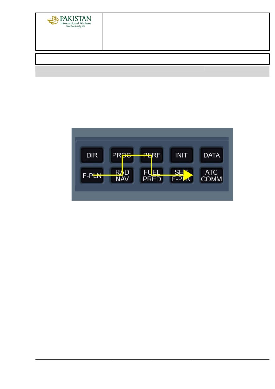
The PF should program the FMGS applying the following sequence:
PIA A318/A319/A320/A321 FLEET
PR-NP-SOP-160 P 9/10
FCTM
D
23 NOV 21
PROCEDURES
NORMAL PROCEDURES
A318/A319/A320/A321
FLIGHT CREW
STANDARD OPERATING PROCEDURES - DESCENT PREPARATION
TECHNIQUES MANUAL
Intentionally left blank
PIA A318/A319/A320/A321 FLEET
PR-NP-SOP-160 P 10/10
FCTM
23 NOV 21
PROCEDURES
NORMAL PROCEDURES
A318/A319/A320/A321
FLIGHT CREW
STANDARD OPERATING PROCEDURES - DESCENT
TECHNIQUES MANUAL
COMPUTATION PRINCIPLES
Ident.: PR-NP-SOP-170-00018923.0001001 / 27 JUL 18
Applicable to: ALL
TOD AND PROFILE COMPUTATION
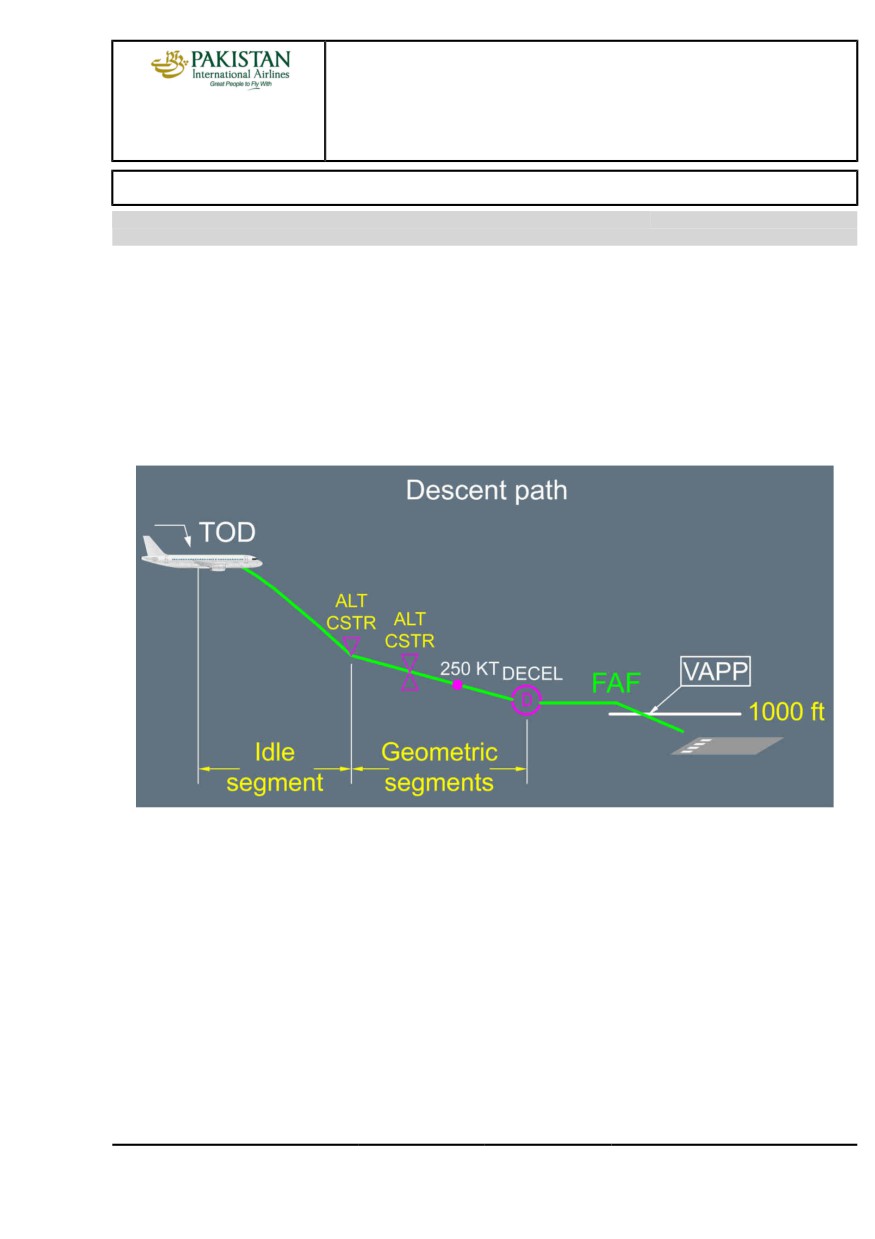
The FMGS calculates the Top Of Descent point (TOD) backwards from a position 1 000 ft on
the final approach with speed at VAPP. It takes into account any descent speed and altitude
constraints and assumes managed speed is used. The first segment of the descent will always be
idle segment until the first altitude constraint is reached. Subsequent segments will be "geometric",
i.e. the descent will be flown at a specific angle, taking into account any subsequent constraints. If
the STAR includes a holding pattern, it is not considered for TOD or fuel computation. The TOD is
displayed on the ND track as a white symbol:
The idle segment assumes a given managed speed flown with idle thrust plus a small amount of
thrust. This gives some flexibility to keep the aircraft on the descent path if engine anti-ice is used
or if winds vary.
During idle segment, the A/THR commands THR IDLE or depending on FMGS standard,
MACH/SPEED.
During geometric segment, the A/THR commands MACH/SPEED.
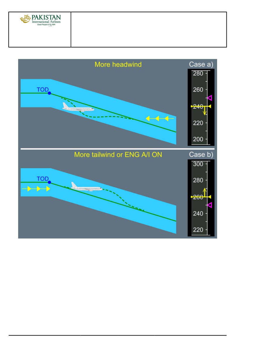
With Descent Profile Optimization option (DPO ), the idle segment assumes a given managed
speed flown at idle thrust. This gives less flexibility to keep the aircraft on the descent path if
engine anti-ice is used or if winds vary. In case of use of engine anti-ice or increased tailwind, the
use of speed brakes may be required to go back on the descent path.
The TOD computed by the FMS is quite reliable provided the flight plan is properly documented
down to the approach.
PIA A318/A319/A320/A321 FLEET
PR-NP-SOP-170 P 1/6
FCTM
A →
04 SEP 18
PROCEDURES
NORMAL PROCEDURES
A318/A319/A320/A321
FLIGHT CREW
STANDARD OPERATING PROCEDURES - DESCENT
TECHNIQUES MANUAL
MANAGED DESCENT SPEED PROFILE
The managed speed is equal to:
- The ECON speed (which may have been modified by the crew on the PERF DES page before
entering DESCENT phase or, during DESCENT phase depending on FMGS standard), or
- The speed constraint or limit when applicable.
GUIDANCE AND MONITORING
Ident.: PR-NP-SOP-170-00018924.0001001 / 27 JUL 18
Applicable to: ALL
INTRODUCTION
To carry out the descent, the crew can use either the managed descent mode (DES) or the
selected descent modes (OP DES or V/S). Both descent modes can be flown either with selected
speed or managed speed.
The modes and monitoring means are actually linked.
The managed DES mode guides the aircraft along the FMS pre-computed descent profile, as long
as it flies along the lateral F-PLN: i.e. DES mode is available if NAV is engaged. As a general rule
when DES mode is used, the descent is monitored using:
- The VDEV called "yoyo" on the PFD and depending on the FMGS standard the associated
Latch symbol, and
- The VDEV digital value on the FMS PROG page, and
- The level arrow on the ND.
The selected OP DES or V/S modes are used when HDG is selected or when ALT CSTR may
be disregarded or for various tactical purposes. As a general rule when OP DES or V/S modes
are used, the descent is monitored using the Energy Circle, (displayed if HDG or TRK modes and
indicating the required distance to descend, decelerate and land from present position) and the
level arrow on the ND. When the aircraft is not far away from the lateral F-PLN (small XTK), the
yoyo on PFD is also a good indicator.
MANAGED DESCENT MODE
The managed descent profile from high altitude is approximately 2.5 °.
As an estimation of the distance to touchdown is required to enable descent profile monitoring, it
is important to ensure that the MCDU F-PLN plan page reflects the expected approach routing.
Any gross errors noted in the descent profile are usually a result of incorrect routing entered in the
MCDU or non-sequencing of F-PLN waypoints, giving a false distance to touchdown.
An accurate WIND and TEMP data insertion on the associated FMS pages will lead to an accurate
DES profile computation and following from FMS.
PIA A318/A319/A320/A321 FLEET
PR-NP-SOP-170 P 2/6
FCTM
← A to B →
04 SEP 18
PROCEDURES
NORMAL PROCEDURES
A318/A319/A320/A321
FLIGHT CREW
STANDARD OPERATING PROCEDURES - DESCENT
TECHNIQUES MANUAL
DESCENT INITIATION
To initiate a managed descent, the pilot will set the ATC cleared altitude on the FCU and push
the ALT selector. DES mode engages and is annunciated on the FMA. If an early descent
were required by ATC, DES mode would give 1 000 ft/min rate of descent, until regaining the
computed profile.
To avoid overshooting the computed descent path, it is preferable to push the FCU ALT selector
a few miles prior to the calculated TOD. This method will ensure a controlled entry into the
descent and is particularly useful in situations of high cruise Mach number or strong upper
winds.
If the descent is delayed, a "DECELERATE" or "T/D REACHED" message appears in white
on the PFD and in amber on the MCDU. Speed should be reduced towards green dot, and
when cleared for descent, the pilot will push for DES and push for managed speed. The speed
reduction prior to descent will enable the aircraft to recover the computed profile more quickly as
it accelerates to the managed descent speed.
DESCENT PROFILE
When DES with managed speed is engaged, the AP/FD guides the aircraft along the
pre-computed descent path determined by a number of factors such as altitude constraints,
wind and descent speed. However, as the actual conditions may differ from those planned, the
DES mode operates within a speed range which can goes up to VMO-5 kt as upper limit and
MANAGED SPD-20 kt as lower limit (limited by VLS). Depending on the FMGS standard and
aircraft position related to the vertical profile, the speed range may not be displayed.
PIA A318/A319/A320/A321 FLEET
PR-NP-SOP-170 P 3/6
FCTM
← B →
04 SEP 18
PROCEDURES
NORMAL PROCEDURES
A318/A319/A320/A321
FLIGHT CREW
STANDARD OPERATING PROCEDURES - DESCENT
TECHNIQUES MANUAL
Managed Descent: Speed Target Range Principle
If the aircraft gets high on the computed descent path:
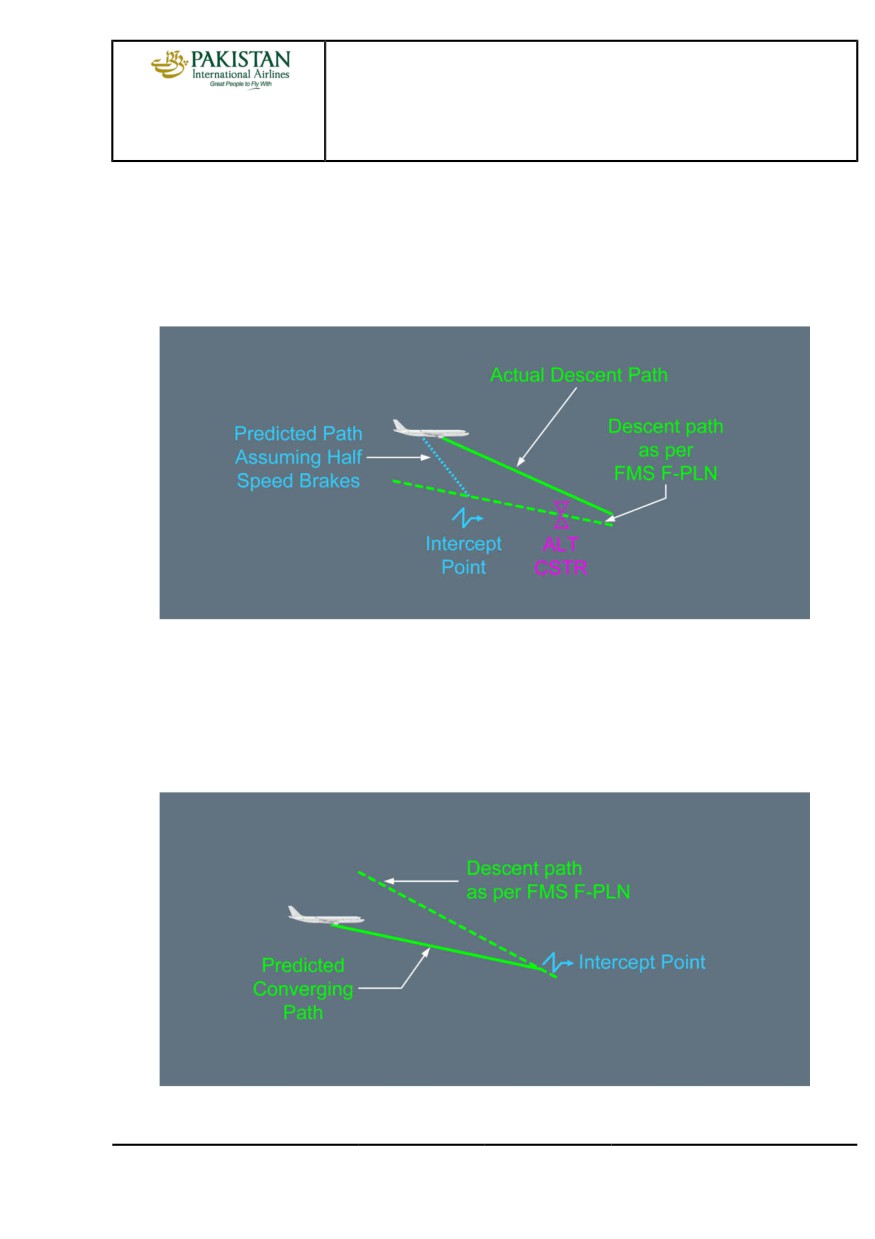
- The speed will increase towards the upper limit of the speed range, to keep the aircraft on
the path with IDLE thrust.
- If the speed reaches the upper limit, THR IDLE is maintained, but the autopilot does not
allow the speed to increase any more, thus the VDEV will slowly increase.
- A path intercept point, which assumes half speedbrake extension, will be displayed on
the ND descent track.
- If speed brakes are not extended, the intercept point will move forward. If it gets close
to an altitude-constrained waypoint, then a message "AIR BRAKES" or "MORE DRAG",
depending of the FMGS standard, will be displayed on the PFD and MCDU.
PIA A318/A319/A320/A321 FLEET
PR-NP-SOP-170 P 4/6
FCTM
← B →
04 SEP 18
PROCEDURES
NORMAL PROCEDURES
A318/A319/A320/A321
FLIGHT CREW
STANDARD OPERATING PROCEDURES - DESCENT
TECHNIQUES MANUAL
This technique allows an altitude constraint to be matched with minimum use of
speedbrakes.
When regaining the descent profile, the speedbrakes should be retracted to prevent the
A/THR applying thrust against speedbrakes. If the speedbrakes are not retracted, the "SPD
BRK" message on the ECAM memo becomes amber.
A/C Above Descent Path
If the aircraft gets low on the computed descent path:
The speed will decrease towards the lower limit of the speed range with idle thrust. When
the lower speed limit is reached the A/THR will revert to SPEED/MACH mode and apply
thrust to maintain the descent path at this lower speed. The path intercept point will be
displayed on the ND, to indicate where the descent profile will be regained.
A/C Below Descent Path
PIA A318/A319/A320/A321 FLEET
PR-NP-SOP-170 P 5/6
FCTM
← B →
04 SEP 18
PROCEDURES
NORMAL PROCEDURES
A318/A319/A320/A321
FLIGHT CREW
STANDARD OPERATING PROCEDURES - DESCENT
TECHNIQUES MANUAL
If selected speed is used:
The descent profile remains unchanged. As the selected speed may differ from the speed
taken into account for pre-computed descent profile and speed deviation range does not
apply, the aircraft may deviate from the descent profile e.g. if the pilot selects 275 kt with a
pre-computed descent profile assuming managed speed 300 kt, VDEV will increase.
SELECTED DESCENT
There are 2 modes for flying a selected descent, namely OP DES and V/S. These modes will be
used for pilot tactical interventions.
V/S mode is automatically selected when HDG or TRK mode is selected by the pilot, while in DES
mode. Furthermore, in HDG or TRK mode, only V/S or OP DES modes are available for descent.
To initiate a selected descent, the pilot should set the ATC cleared altitude on the FCU and pull
the ALT selector. OP DES mode engages and is annunciated on the FMA. In OP DES mode, the
A/THR commands THR IDLE and the speed is controlled by the THS.
Speed may be either managed or selected. In managed speed, the descent speed is displayed
only as a magenta target but there is no longer a speed target range since the pre-computed flight
profile does not apply.
The AP/FD will not consider any MCDU descent altitude constraints and will fly an unrestricted
descent down to the FCU selected altitude.
If the crew wishes to increase the rate of descent, OP DES mode can be used, selecting a higher
speed. Speedbrake is very effective in increasing descent rate but should be used with caution at
high altitude due to the associated increase in VLS.
If the pilot wishes to shallow the descent path, V/S can be used. A/THR reverts to SPEED mode.
In this configuration, the use of speedbrakes is not recommended to reduce speed, since this
would lead to thrust increase and the speed would be maintained.
PIA A318/A319/A320/A321 FLEET
PR-NP-SOP-170 P 6/6
FCTM
← B
04 SEP 18
PROCEDURES
NORMAL PROCEDURES
A318/A319/A320/A321
FLIGHT CREW
STANDARD OPERATING PROCEDURES - HOLDING
TECHNIQUES MANUAL
HOLDING SPEED AND CONFIGURATION
Ident.: PR-NP-SOP-180-00018934.0001001 / 20 MAR 17
Applicable to: ALL
Whenever holding is anticipated, it is preferable to maintain cruise level and reduce speed to green
dot, with ATC clearance, to minimize the holding requirement. As a rule of thumb, a M 0.05 decrease
during 1 h equates to 4 min hold. However, other operational constraints might make this option
inappropriate.
A holding pattern can be inserted at any point in the flight plan or may be included as part of the
STAR. In either case, the holding pattern can be modified by the crew.
If a hold is to be flown, provided NAV mode is engaged and the speed is managed, an automatic
speed reduction will occur to achieve the hold speed when entering the holding pattern.
The default hold speed is the lowest of the following:
- Maximum Endurance speed
- ICAO limit holding speed
- Speed constraint (if any).
When no specific speed limit applies, the default hold speed is the Maximum Endurance speed,
which is approximately equal to Green Dot and provides the lowest hourly fuel consumption.
If the Maximum Endurance speed is greater than the ICAO or state maximum holding speed, the
crew should select flap 1 below 20 000 ft and fly S speed. Fuel consumption will be increased when
holding in anything other than clean configuration and Maximum Endurance speed.
IN THE HOLDING PATTERN
Ident.: PR-NP-SOP-180-00018935.0001001 / 25 JUL 17
Applicable to: ALL
The holding pattern is not included in the descent path computation since the FMGS does not know
how many patterns will be flown. When the holding fix is sequenced, the FMGS assumes that only
one holding pattern will be flown and updates predictions accordingly. Once in the holding pattern,
the VDEV indicates the vertical deviation between current aircraft altitude and the altitude at which
the aircraft should cross the exit fix in order to be on the descent profile.
The DES mode guides the aircraft down at -1 000 ft/min whilst in the holding pattern until reaching
the cleared altitude or altitude constraint.
When in the holding pattern, LAST EXIT UTC/FUEL information is displayed on the MCDU HOLD
page. These predictions are based upon the fuel policy requirements specified on the MCDU FUEL
PIA A318/A319/A320/A321 FLEET
PR-NP-SOP-180 P 1/2
FCTM
A to B →
05 SEP 17
PROCEDURES
NORMAL PROCEDURES
A318/A319/A320/A321
FLIGHT CREW
STANDARD OPERATING PROCEDURES - HOLDING
TECHNIQUES MANUAL
PRED page with no extra fuel, assuming the aircraft will divert. The crew should be aware that this
information is computed with defined assumptions e.g.:
- Aircraft weight being equal to landing weight at primary destination
- Flight at FL 220 if distance to ALTN is less than 200 NM, otherwise FL 310 performed at maximum
range speed.
- Constant wind (as entered in alternate field of the DES WIND page).
- Constant delta ISA (equal to delta ISA at primary destination)
- Airway distance for a company route, otherwise direct distance.
Alternate airport may be modified using the MCDU ALTN airport page which can be accessed by a
lateral revision at destination.
To exit the holding pattern, the crew should select either:
- IMM EXIT (The aircraft will return immediately to the hold fix, exit the holding pattern and resume
its navigation), or
- HDG if radar vectors, or
- DIR TO if radar vectors.
PIA A318/A319/A320/A321 FLEET
PR-NP-SOP-180 P 2/2
FCTM
← B
05 SEP 17
PROCEDURES
NORMAL PROCEDURES
A318/A319/A320/A321
FLIGHT CREW
STANDARD OPERATING PROCEDURES - APPROACH
TECHNIQUES MANUAL
General
INTRODUCTION
Ident.: PR-NP-SOP-190-GEN-00016386.0001001 / 20 MAR 17
Applicable to: ALL
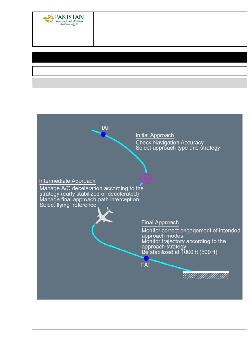
All approaches are divided into three parts (i.e initial, intermediate and final) where the flight crew
should perform associated configuration management and guidance management.
Techniques, which apply to specific approach types are covered in the appropriate chapters.
PIA A318/A319/A320/A321 FLEET
PR-NP-SOP-190-GEN P 1/2
FCTM
A
22 MAR 17
PROCEDURES
NORMAL PROCEDURES
A318/A319/A320/A321
FLIGHT CREW
STANDARD OPERATING PROCEDURES - APPROACH
TECHNIQUES MANUAL
DISCONTINUED APPROACH
Ident.: PR-NP-SOP-190-GEN-00016390.0001001 / 20 MAR 17
Applicable to: ALL
The discontinued approach is an alternative technique to the GO AROUND procedure to interrupt an
approach when the aircraft is at or above the selected FCU altitude.
Contrary to the GO AROUND procedure, the discontinued approach technique does not require the
flight crew to set the thrust levers to TOGA detent.
The flight crew should initiate the discontinued approach technique with the callout: “CANCEL
APPROACH”.
The first action of the flight crew is to disengage and disarm any AP/FD approach mode, by pressing
on the APPR pb or LOC pb.
PIA A318/A319/A320/A321 FLEET
PR-NP-SOP-190-GEN P 2/2
FCTM
B
22 MAR 17
PROCEDURES
NORMAL PROCEDURES
A318/A319/A320/A321
FLIGHT CREW
STANDARD OPERATING PROCEDURES - APPROACH
TECHNIQUES MANUAL
Configuration Management
INITIAL APPROACH
Applicable to: ALL
Ident.: PR-NP-SOP-190-CONF-A-00018950.0004001 / 05 MAR 19
F-PLN SEQUENCING
When in NAV mode, the F-PLN will sequence automatically. In HDG/TRK mode, the F-PLN
waypoints will sequence automatically only if the aircraft flies close to the planned route. Correct
F-PLN sequencing is important to ensure that the planned missed approach route is available
in case of go-around and to ensure correct predictions. A good cue to monitor the proper F-PLN
sequencing is the TO waypoint on the upper right side of the ND, which should remain meaningful.
If ATC provides radar vectors and automatic waypoint sequencing does not occur, the flight crew
should use the DIR TO RADIAL IN function, or delete the FROM waypoint on the F-PLN page until
the next likely waypoint to be overflown is displayed as the TO waypoint on the ND. This ensures:
- A proper F-PLN sequencing
- A comprehensive ND display
- An assistance for lateral interception
- The VDEV to be computed on reasonable distance assumptions.
For more information about the waypoint sequencing, Refer to FCOM/DSC-22_20-30-10-05
General.
However, considerations should be given to the following:
- A radial is to be inserted in the MCDU. In the following example, the final approach course is
90 ° corresponding to radial 270 °.
- DIR TO RADIAL IN must not be used beyond the Final Descent Point, in order to ensure that
the vertical profile in final is unchanged.
- Using DIR TO or DIR TO RADIAL IN function arms the NAV mode. If NAV mode is not
appropriate, the flight crew will pull the HDG knob to disarm it.
- Deceleration will not occur automatically as long as lateral mode is HDG.
The flight crew should sequence the F-PLN first, and then press the APPR pb. When the LOC
mode (or F-LOC mode for aircraft fitted with FLS) is armed or engaged, the flight crew should not
perform a DIR TO, in order to sequence the F-PLN as this will result in the FMGS to revert to the
NAV mode. In this case, the LOC mode (or F-LOC mode for aircraft fitted with FLS) will have to be
re-armed and re-engaged, increasing workload unduly.
PIA A318/A319/A320/A321 FLEET
PR-NP-SOP-190-CONF P 1/6
FCTM
A →
23 NOV 21
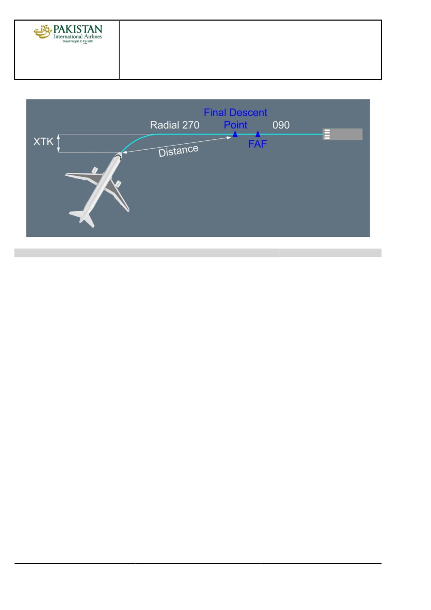
PROCEDURES
NORMAL PROCEDURES
A318/A319/A320/A321
FLIGHT CREW
STANDARD OPERATING PROCEDURES - APPROACH
TECHNIQUES MANUAL
Use of DIR TO radial in facility
Ident.: PR-NP-SOP-190-CONF-A-00018951.0001001 / 20 MAR 17
APPROACH PHASE ACTIVATION
Activation of the approach phase will initiate a deceleration towards VAPP or the speed constraint
inserted at the Final Descent Point (FDP).
When in NAV mode with managed speed, the approach phase activates automatically when
sequencing the deceleration pseudo-waypoint. If an early deceleration is required, the approach
phase can be activated on the MCDU PERF APPR page. When the approach phase is activated,
the magenta target speed becomes VAPP.
When in HDG mode, e.g. for radar vectoring, the crew will activate the approach phase manually.
APPROACH SPEED TECHNIQUE
There are two approach techniques:
- Decelerated approach
- Early stabilized approach.
DECELERATED APPROACH
This technique refers to an approach where the aircraft reaches 1 000 ft in the landing
configuration at VAPP. In most cases, this equates to the aircraft being in CONF 1 and at S
speed at the FDP. This is the preferred technique for an approach using vertical managed
guidance. The deceleration pseudo waypoint assumes a decelerated approach technique.
EARLY STABILIZED APPROACH
This technique refers to an approach where the aircraft reaches the FDP in the landing
configuration at VAPP. This technique is recommended for non-precision approaches
PIA A318/A319/A320/A321 FLEET
PR-NP-SOP-190-CONF P 2/6
FCTM
← A →
23 NOV 21
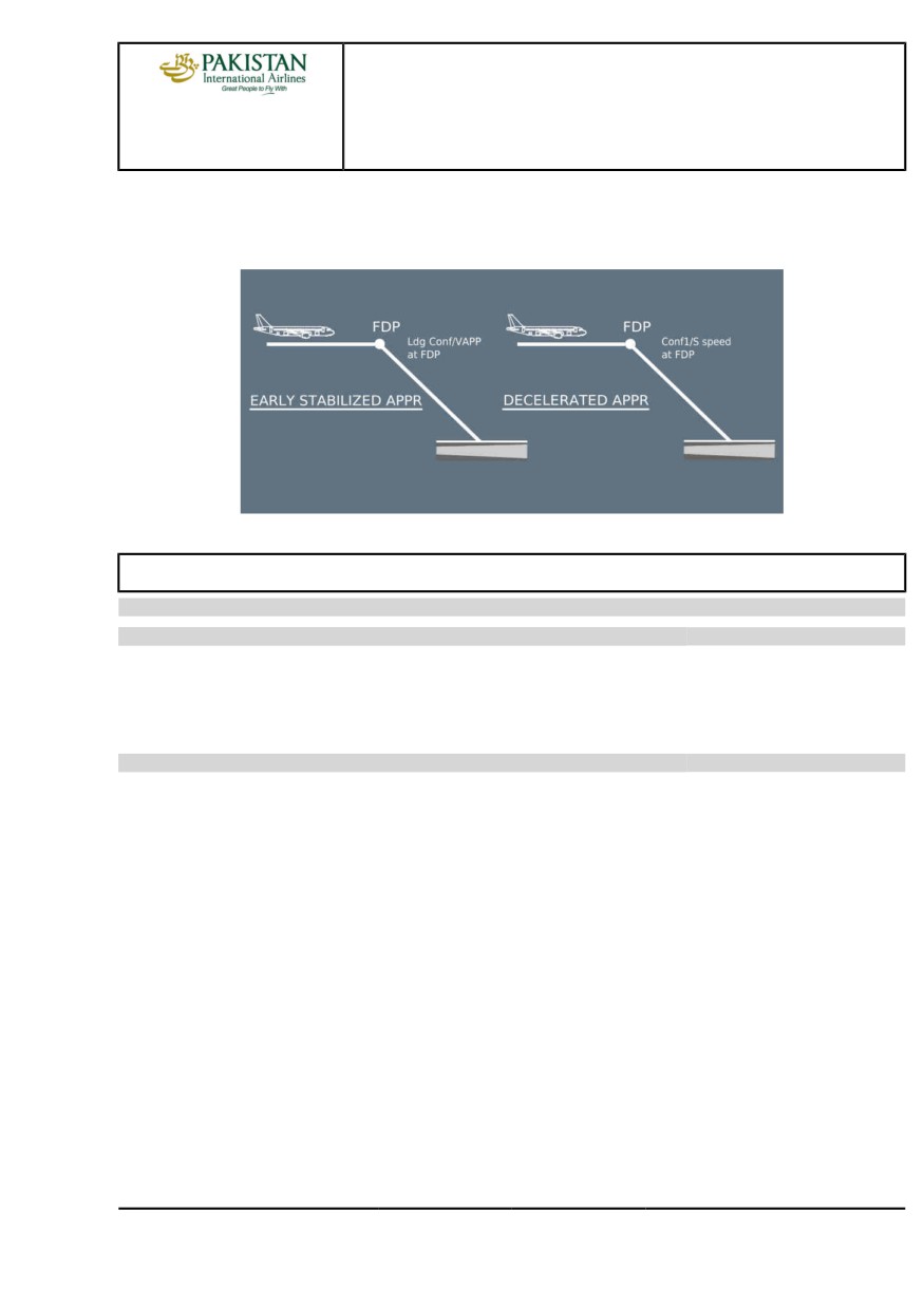
PROCEDURES
NORMAL PROCEDURES
A318/A319/A320/A321
FLIGHT CREW
STANDARD OPERATING PROCEDURES - APPROACH
TECHNIQUES MANUAL
(LOC FPA, NAV FPA and TRK FPA). To get a valuable deceleration pseudo waypoint and to
ensure a timely deceleration, the pilot should enter VAPP as a speed constraint at the FDP.
Early Stabilized versus Decelerated Approach
INTERMEDIATE APPROACH
Applicable to: ALL
Ident.: PR-NP-SOP-190-CONF-B-00018952.0001001 / 20 MAR 17
GENERAL
The purpose of the intermediate approach is to bring the aircraft at the proper speed, altitude and
configuration at FDP.
Ident.: PR-NP-SOP-190-CONF-B-00018953.0001001 / 20 MAR 17
DECELERATION AND CONFIGURATION CHANGE
Managed speed is recommended for the approach. Once the approach phase has been activated,
the A/THR will guide aircraft speed towards the maneuvering speed of the current configuration,
whenever higher than VAPP, e.g. green dot for CONF 0, S speed for CONF 1 etc.
To achieve a constant deceleration and to minimize thrust variation, the crew should extend the
next configuration when reaching the current configuration maneuvering speed +10 kt (IAS must
be lower than VFE next), e.g. when the speed reaches green dot +10 kt, the crew should select
CONF 1. Using this technique, the mean deceleration rate will be approximately 10 kt/NM in level
flight. This deceleration rate will be twice i.e. 20 kt/NM, with the use of the speedbrakes.
If selected speed is to be used to comply with ATC, the requested speed should be selected on
the FCU. A speed below the manoeuvring speed of the present configuration may be selected
provided it is above VLS. When the ATC speed constraint no longer applies, the pilot should push
the FCU speed selector to resume managed speed.
PIA A318/A319/A320/A321 FLEET
PR-NP-SOP-190-CONF P 3/6
FCTM
← A to B →
23 NOV 21
PROCEDURES
NORMAL PROCEDURES
A318/A319/A320/A321
FLIGHT CREW
STANDARD OPERATING PROCEDURES - APPROACH
TECHNIQUES MANUAL
When flying the intermediate approach in selected speed, the crew will activate the approach
phase. This will ensure further proper speed deceleration when resuming managed speed;
otherwise the aircraft will accelerate to the previous applicable descent phase speed.
In certain circumstances, e.g. tail wind or high weight, the deceleration rate may be insufficient.
In this case, the landing gear may be lowered, preferably below 220 kt (to avoid gear doors
overstress), and before selection of Flap 2. Speedbrakes can also be used to increase the
deceleration rate but the crew should be aware of:
- The increase in VLS with the use of speedbrakes
- The limited effect at low speeds
- The speed brake auto-retraction when selecting CONF FULL (A319, A320) or CONF 3 (A321
only) There is no speed brake auto-retraction on A318.
FINAL APPROACH
Applicable to: ALL
Ident.: PR-NP-SOP-190-CONF-C-00018957.0001001 / 03 NOV 21
USE OF A/THR
The flight crew should use the A/THR for approaches as it provides accurate speed control. The
PF should keep the hand on the thrust levers so as to be prepared to react if needed.
During final approach, the managed target speed moves along the speed scale as a function of
wind variation. If ATC gives a new wind for landing, the flight crew will update it on MCDU PERF
APPR page.
The flight crew should ideally check the reasonableness of the target speed by referring to GS on
the top left on ND. If the A/THR performance is unsatisfactory, the PF should disconnect it and
control the thrust manually.
If the PF uses manual thrust for landing, the PF should disconnect the A/THR at 1 000 ft AAL at
the latest.
Ident.: PR-NP-SOP-190-CONF-C-00018958.0001001 / 20 MAR 17
TRAJECTORY STABILIZATION
The first prerequisite for safe final approach and landing is to stabilize the aircraft as per criteria
given in the FCOM (Refer to FCOM/PRO-NOR-SOP-18-A Stabilization Criteria).
If, for any reason, one flight parameter deviates from stabilized conditions, the PM will make a
callout.
PIA A318/A319/A320/A321 FLEET
PR-NP-SOP-190-CONF P 4/6
FCTM
← B to C →
23 NOV 21
PROCEDURES
NORMAL PROCEDURES
A318/A319/A320/A321
FLIGHT CREW
STANDARD OPERATING PROCEDURES - APPROACH
TECHNIQUES MANUAL
Following a PM flight parameter exceedance call out, the suitable PF response will be:
- Acknowledge the PM callout, for proper crew coordination purposes
- Take immediate corrective action to control the exceeded parameter back into the defined
stabilized conditions
- Assess whether stabilized conditions will be recovered early enough prior to landing, otherwise
initiate a go-around.
Ident.: PR-NP-SOP-190-CONF-C-00019361.0001001 / 20 MAR 17
AP DISCONNECTION
During the final approach with the AP engaged, the aircraft will be stabilized. Therefore, when
disconnecting the AP for a manual landing, the pilot should avoid the temptation to make large
inputs on the sidestick.
The pilot should disconnect the autopilot early enough to resume manual control of the aircraft and
to evaluate the drift before flare. During crosswind conditions, the pilot should avoid any tendency
to drift downwind.
Some common errors include:
- Descending below the final path, and/or
- reducing the drift too early.
PIA A318/A319/A320/A321 FLEET
PR-NP-SOP-190-CONF P 5/6
FCTM
← C
23 NOV 21
PROCEDURES
NORMAL PROCEDURES
A318/A319/A320/A321
FLIGHT CREW
STANDARD OPERATING PROCEDURES - APPROACH
TECHNIQUES MANUAL
Intentionally left blank
PIA A318/A319/A320/A321 FLEET
PR-NP-SOP-190-CONF P 6/6
FCTM
23 NOV 21
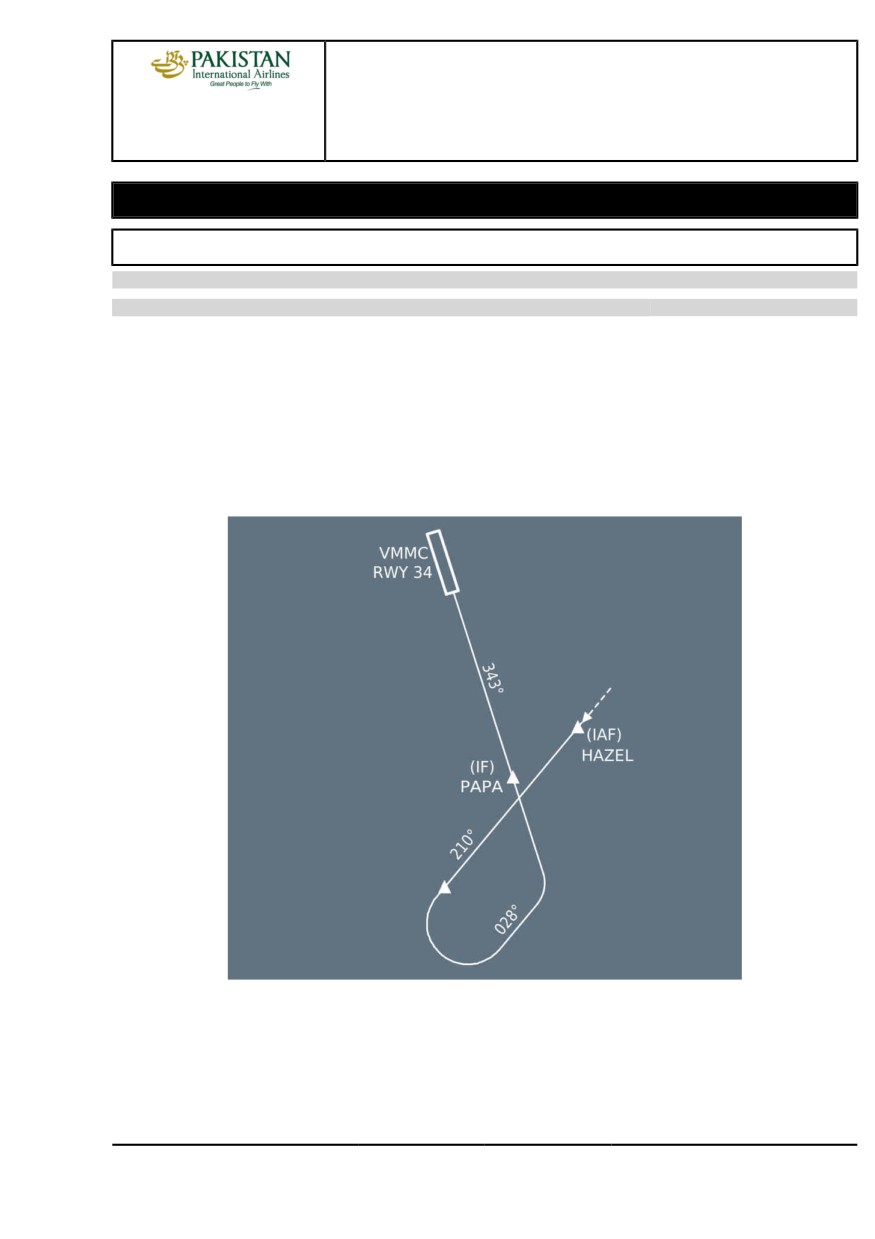
PROCEDURES
NORMAL PROCEDURES
A318/A319/A320/A321
FLIGHT CREW
STANDARD OPERATING PROCEDURES - APPROACH
TECHNIQUES MANUAL
Guidance Management
APPROACH USING LOC G/S GUIDANCE
Applicable to: ALL
Ident.: PR-NP-SOP-190-GUI-A-00019357.0001001 / 20 MAR 17
INTERCEPTION OF FINAL APPROACH COURSE
When cleared for the ILS and when on the intercept trajectory for the LOC, the flight crew should
press the APPR pb. This arms the approach modes, and LOC and GS are displayed in blue on the
FMA. At this stage, the second AP, if available, should be selected.
In the example below, if the ATC clears the aircraft for the procedure at HAZEL, the flight crew
must delay the push on the APPR pb, as the aircraft is not on the intercept trajectory for the LOC:
VMMC ILS RWY34 via HAZEL
If the ATC clears for a LOC capture only, the flight crew will press the LOC pb-sw on the FCU.
If the ATC clears for approach at a significant distance, e.g. 30 NM, the flight crew should be
aware that the G/S may be perturbed and CAT 1 will be displayed on FMA till a valid Radio
Altimeter signal is received.
PIA A318/A319/A320/A321 FLEET
PR-NP-SOP-190-GUI P 1/28
FCTM
A →
12 JAN 22
PROCEDURES
NORMAL PROCEDURES
A318/A319/A320/A321
FLIGHT CREW
STANDARD OPERATING PROCEDURES - APPROACH
TECHNIQUES MANUAL
Ident.: PR-NP-SOP-190-GUI-A-00019358.0001001 / 04 NOV 20
GLIDE SLOPE INTERCEPTION FROM ABOVE
The following procedure must only be applied when established on the localizer. There are a
number of factors which might lead to a glide slope interception from above. In such a case, the
flight crew must react without delay to meet the stabilization criteria.
In order to get the best rate of descent when cleared by ATC and below the limiting speeds, the
flight crew should lower the landing gear and select flaps as required (at least CONF 2 should
be selected to ensure that the aircraft speed will not increase). Speedbrakes may also be used,
noting the considerations detailed in the subsection "Deceleration and configuration change"
earlier in this chapter.
When cleared to intercept the glide slope, the flight crew should:
- Press the APPR pb on FCU and confirm G/S is armed and LOC engaged, monitor the vertical
interception
- Select the FCU altitude above aircraft altitude to avoid unwanted ALT* engagement
- Select V/S 1 500 ft/min initially. V/S in excess of 2 000 ft/min will result in the speed increasing
towards VFE.
The use of V/S mode ensures that the A/THR is in SPEED mode.
The flight crew should carefully monitor the rate of descent to avoid exceeding VFE . When
approaching the G/S path, G/S* will engage. The flight crew should monitor the G/S capture with
raw data (pitch and G/S deviation). The go-around altitude should be set on the FCU at G/S*.
APPROACH USING LOC G/S FOR CATII CATIII
Applicable to: ALL
Ident.: PR-NP-SOP-190-GUI-B-00019399.0001001 / 20 MAR 17
CAT II and CAT III approaches are flown to very low DH (or without DH) with very low RVR. The
guidance of the aircraft on the ILS beam and the guidance of the aircraft speed must be consistently
of high performance and accurate so that an automatic landing and roll out can be performed in good
conditions and, the acquisition of visual cues is achieved and the aircraft properly stabilized. Hence,
- The automatic landing is required in CAT III operations including roll out in CAT IIIB.
- The automatic landing is the preferred landing technique in CAT II conditions
- Any failures of the automated systems shall not significantly affect the aircraft automatic landing
system performance
- The crew procedures and task sharing allow to rapidly detect any anomaly and thus lead to the
right decision
PIA A318/A319/A320/A321 FLEET
PR-NP-SOP-190-GUI P 2/28
FCTM
← A to B →
12 JAN 22