Airbus A318/319/320/321. FLIGHT CREW TECHNIQUES MANUAL (2005-2022) - page 6
AIRCRAFT SYSTEMS
BIRD
A318/A319/A320/A321
FLIGHT CREW
TECHNIQUES MANUAL
INTRODUCTION
Ident.: AS-BIRD-00016266.0001001 / 04 SEP 18
Applicable to: ALL
Two flying references may be used on the PFD:
- The attitude
- The Flight Path Vector (FPV), called the "bird".
When TRK/FPA is selected on the FCU, the "bird" is the flight reference with the TRK and FPA as
basic guidance parameters.
When HDG/VS is selected on the FCU, "bird" is off, and the attitude is the flight reference with HDG
and VS as basic guidance parameters.
The attitude flight reference should be used for dynamic manoeuvres, for example, take-off or
go-around. An action on the sidestick has an immediate effect on the aircraft attitude. The flight crew
can monitor this flight reference directly and accurately during these manoeuvres.
RELIABILITY
The bird is computed from IRS data and is affected by inertial errors. During the approach, the
flight crew may detect a small track error, usually up to +/-2 °.
The bird is also computed from static pressure information. Therefore, if the altitude information is
not reliable, the flight crew must consider the bird as not reliable.
PRACTICAL USE OF THE BIRD
Applicable to: ALL
Ident.: AS-BIRD-A-00018465.0001001 / 20 MAR 17
GENERAL RULE
When using the "bird", the flight crew should first change attitude, and then check the result with
reference to the "bird".
Ident.: AS-BIRD-A-00018467.0001001 / 20 MAR 17
APPROACH USING FPA GUIDANCE
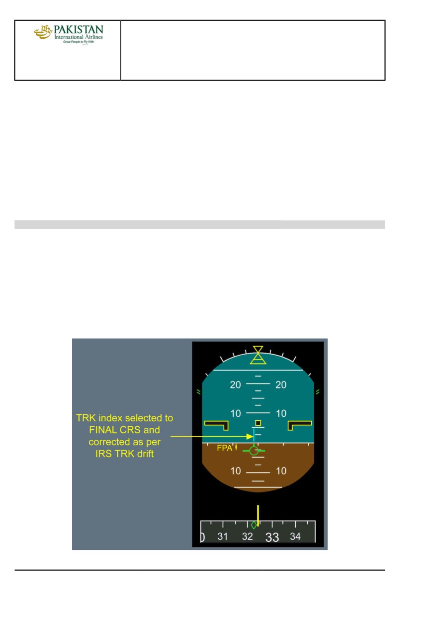
The FPV is particularly useful for this type of approach. The flight crew can select values for the
inbound track and final descent path angle on the FCU. Once established inbound, only minor
corrections should be required to maintain an accurate approach path. The flight crew can monitor
the tracking and descent flight path, with reference to the track indicator and the "bird".
However, the flight crew should understand that the "bird" only indicates a flight path angle and
track, and does not provide guidance to a ground-based radio facility. Therefore, even if the
"bird" indicates that the aircraft is flying with the correct flight path angle and track, this does not
necessarily mean that the aircraft is on the correct final approach path.
PIA A318/A319/A320/A321 FLEET
AS-BIRD P 1/4
FCTM
A to B →
04 SEP 18
AIRCRAFT SYSTEMS
BIRD
A318/A319/A320/A321
FLIGHT CREW
TECHNIQUES MANUAL
The TRK-FPA Flight Director (FD) is particularly useful for guiding the aircraft during non-precision
approaches, although, it can also be used at other times. When using this mode of the FD, the
pilot places the FPV symbol in the center of the flight path director (FPD) symbol. This is similar to
using the FD in HDG-V/S, when the pilot puts the center of the fixed aircraft symbol at the center
of the crossed bars of the FD. If the FCU is set on the correct track and flight path angle, and if the
FPV and the FPD are aligned, they will guide the aircraft along a trajectory that is stabilized with
respect to the ground, whereas when the pilot is using HDG-V/S, the trajectory is stabilized with
respect to the air. However, if the aircraft is disturbed from this ideal trajectory, merely following
the FPD will result in its following a trajectory that is parallel to the intended trajectory. Thus, when
the aircraft is disturbed from the original trajectory, the pilot must adjust either its track or its flight
path angle or both in order to obtain guidance back to the original trajectory.
Ident.: AS-BIRD-A-00018477.0001001 / 20 MAR 17
VISUAL CIRCUITS
The FPV can be used as a cross-reference, when flying visual circuits. On the downwind leg, the
flight crew should position the wings of the "bird" on the horizon, in order to maintain level flight.
The downwind track should be set on the FCU. The flight crew should position the tail of the "bird"
on the blue track index on the PFD , in order to maintain the desired track downwind.
On the final inbound approach, the track index should be set to the final approach course of the
runway. A standard 3 ° approach path is indicated, when the top of the bird's tail is immediately
below the horizon, and the bottom of the "bird" is immediately above the 5 ° nose down marker.
PIA A318/A319/A320/A321 FLEET
AS-BIRD P 2/4
FCTM
← B →
04 SEP 18
AIRCRAFT SYSTEMS
BIRD
A318/A319/A320/A321
FLIGHT CREW
TECHNIQUES MANUAL
Ident.: AS-BIRD-A-00018478.0001001 / 20 MAR 17
FINAL APPROACH
The "bird" is a very useful flight reference, because it provides the trajectory parameters, and
quickly warns the pilot of downburst. In addition, together with the GS MINI protection, it is
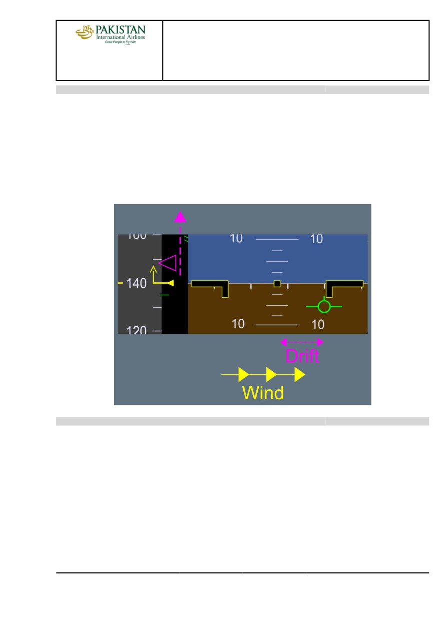
an excellent indicator of shears or wind variations. The position of the "bird" in relation to the
fixed aircraft symbol provides an immediate indication of the wind direction. Therefore, when
approaching the minimum, the flight crew knows in which direction to search for the runway.
If the target approach speed symbol moves upward, this indicates that there is headwind gust. If
the "bird" drifts to the right, this indicates that there is wind from the left.
Ident.: AS-BIRD-A-00018479.0002001 / 20 MAR 17
GO-AROUND
The pilot must take care when making a go-around with the FPV selected. There is inevitably
some lag between the pilot’s raising the nose to commence the go-around and the aircraft’s
responding by changing its trajectory.
For the go-around, the appropriate flight reference is the attitude, because go-around is a dynamic
maneuver. Therefore, when performing a go-around, regardless of the previously-selected flight
reference, upon selection of TOGA, the FD bars are automatically restored in SRS/GA TRACK
modes, and the "bird" is automatically removed.
PIA A318/A319/A320/A321 FLEET
AS-BIRD P 3/4
FCTM
← B
04 SEP 18
AIRCRAFT SYSTEMS
BIRD
A318/A319/A320/A321
FLIGHT CREW
TECHNIQUES MANUAL
Intentionally left blank
PIA A318/A319/A320/A321 FLEET
AS-BIRD P 4/4
FCTM
04 SEP 18
AIRCRAFT SYSTEMS
FLIGHT GUIDANCE
A318/A319/A320/A321
FLIGHT CREW
AUTO FLIGHT
TECHNIQUES MANUAL
OBJECTIVE
Ident.: AS-FG-10-1-00018207.0001001 / 20 MAR 17
Applicable to: ALL
The Flight Director (FD) and the Auto Pilot (AP) assist the flight crew to fly the aircraft within the
normal flight.
To achieve this objective:
- The FD provides adequate attitude or flight path orders and enables the Pilot Flying (PF) to
accurately fly the aircraft manually
- The AP takes over routine tasks. This give the PF the necessary time and resources to assess the
overall operational situation.
MANAGED AND SELECTED MODES
Ident.: AS-FG-10-1-00016271.0001001 / 20 MAR 17
Applicable to: ALL
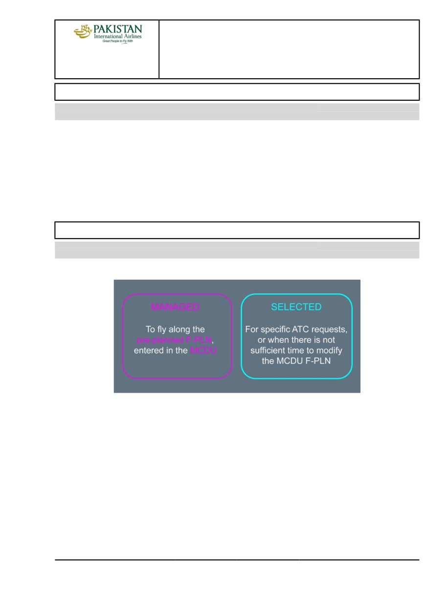
The choice of mode is a strategic decision that is taken by the PF.
Managed modes require:
- Good FMS navigation accuracy (or GPS PRIMARY)
- An appropriate ACTIVE F-PLN (i.e. the intended lateral and vertical trajectory is entered, and the
sequencing of the F-PLN is monitored).
If these two conditions are not fulfilled, revert to selected mode.
PIA A318/A319/A320/A321 FLEET
AS-FG-10-1 P 1/4
FCTM
A to B
22 MAR 17
AIRCRAFT SYSTEMS
FLIGHT GUIDANCE
A318/A319/A320/A321
FLIGHT CREW
AUTO FLIGHT
TECHNIQUES MANUAL
MAIN INTERFACES WITH THE AP/FD
Ident.: AS-FG-10-1-00016272.0001001 / 20 MAR 17
Applicable to: ALL
*The DIR TO function is an exception to this rule.
OPERATIONAL TECHNIQUES
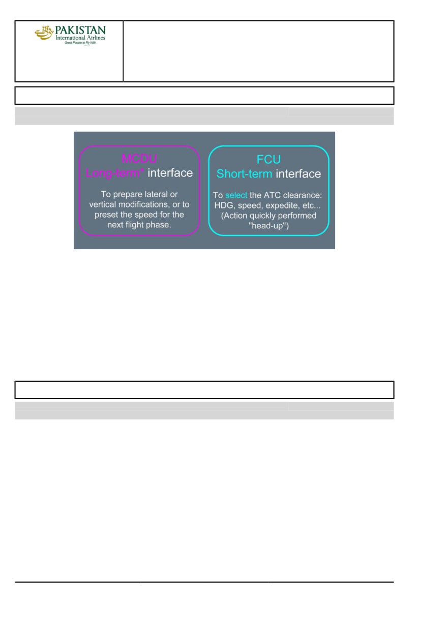
With the FMS, anticipate flight plan updates by preparing:
- EN ROUTE DIVERSIONS
- DIVERSION TO ALTN
- CIRCLING
- LATE CHANGE OF RWY
This enables the MCDU to be used for short-term actions.
AP/FD MONITORING
Ident.: AS-FG-10-1-00016273.0001001 / 20 MAR 17
Applicable to: ALL
The FMA indicates the status of the AP, FD and A/THR and their corresponding operating modes.
The PF must monitor the FMA and announce any FMA change. The flight crew uses the FCU or
MCDU to give orders to the AP/FD. The aircraft is expected to fly in accordance with these orders.
The main concern for the flight crew should be:
- WHAT IS THE AIRCRAFT EXPECTED TO FLY NOW?
- WHAT IS THE AIRCRAFT EXPECTED TO FLY NEXT?
If the aircraft does not fly as expected:
- If in managed mode, select the desired target, or
- Disengage the autopilot, and fly the aircraft manually.
PIA A318/A319/A320/A321 FLEET
AS-FG-10-1 P 2/4
FCTM
C to D
22 MAR 17
AIRCRAFT SYSTEMS
FLIGHT GUIDANCE
A318/A319/A320/A321
FLIGHT CREW
AUTO FLIGHT
TECHNIQUES MANUAL
RECOMMENDED PRACTICE FOR AUTOPILOT (AP) ENGAGEMENT
Ident.: AS-FG-10-1-00016274.0001001 / 20 MAR 17
Applicable to: ALL
Before engaging the AP, the flight crew should:
- Fly the aircraft on the intended path
- Check on the FMA that the Flight Director (FD) is engaged with the appropriate guidance modes
for the intended flight path. If not, set the FD on, and the appropriate guidance mode(s) as
required
- Center the FD bars with the aircraft symbol on the PFD.
Note:
Engaging the AP while large orders are required to achieve the intended flight path may
result in an AP overshoot of the intended vertical or lateral target. This situation can
surprise the flight crew, due to the resulting large pitch/roll changes and thrust variations.
USE OF THE FD WITHOUT THE AP
Ident.: AS-FG-10-1-00016275.0001001 / 20 MAR 17
Applicable to: ALL
When manually flying the aircraft with the FDs ON, the FD bars or the FPD symbol provide lateral
and vertical orders in accordance with the active modes that the flight crew selects.
Therefore:
- Fly with a centered FD or FPD
- If not using FD orders, turn off the FD. It is strongly recommended to turn off the FDs to ensure
that the A/THR is in SPEED mode if the A/THR is active.
PIA A318/A319/A320/A321 FLEET
AS-FG-10-1 P 3/4
FCTM
E to F
22 MAR 17
AIRCRAFT SYSTEMS
FLIGHT GUIDANCE
A318/A319/A320/A321
FLIGHT CREW
AUTO FLIGHT
TECHNIQUES MANUAL
Intentionally left blank
PIA A318/A319/A320/A321 FLEET
AS-FG-10-1 P 4/4
FCTM
22 MAR 17
AIRCRAFT SYSTEMS
FLIGHT GUIDANCE
A318/A319/A320/A321
FLIGHT CREW
AUTOTHRUST
TECHNIQUES MANUAL
NORMAL OPERATIONS
Ident.: AS-FG-10-2-00018246.0001001 / 03 NOV 21
Applicable to: ALL
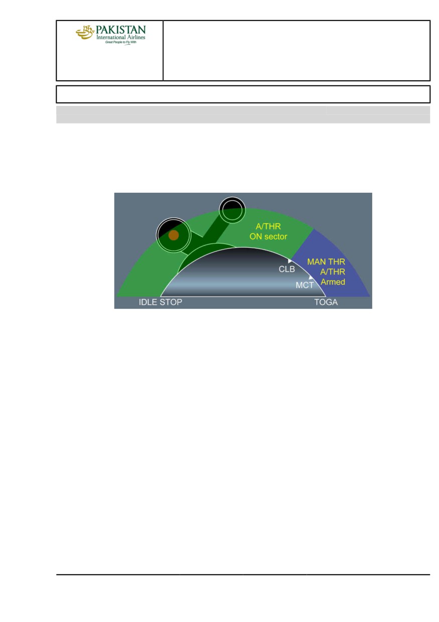
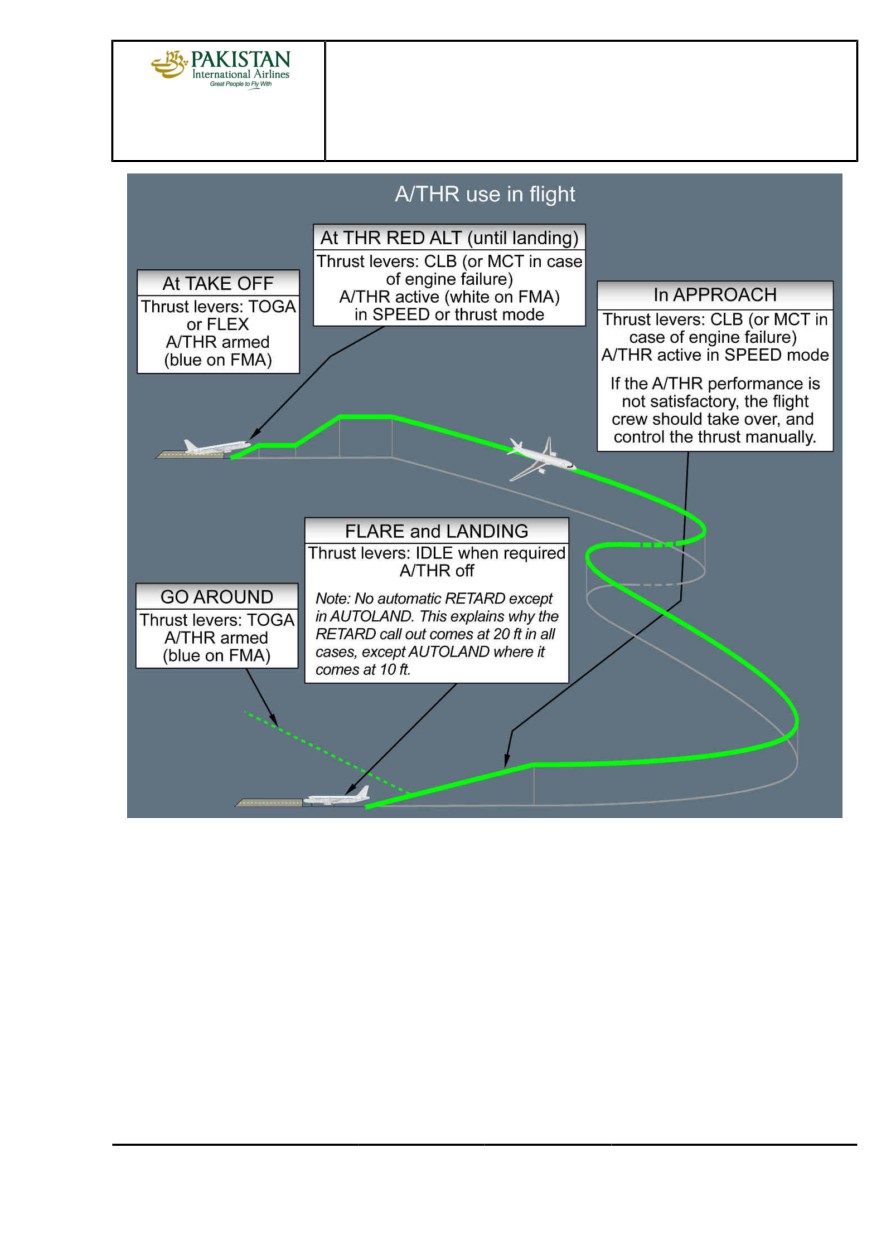
The A/THR can only be active, when the thrust levers are between IDLE and the CLB detent.
When the thrust levers are beyond the CLB detent, thrust is controlled manually to the thrust lever
Angle, and the A/THR is armed (A/THR appears in blue on the FMA). This means that the A/THR
is ready to be re-activated, when the flight crew sets the thrust levers back to the CLB detent (or
below).
AT TAKEOFF
The thrust levers are set either full forward to TOGA, or to the FLX detent. Thrust is manually
controlled to the TLA, and A/THR is armed. The FMA indicates this in blue.
AFTER TAKEOFF
When the aircraft reaches THR RED ALT, the flight crew sets the thrust levers back to the CLB
detent. This activates A/THR. MAX CLB will, therefore, be the maximum normal thrust setting that
will be commanded by the A/THR in CLB, CRZ, DES, or APPR, as required.
DURING APPROACH
The flight crew should use autothrust for approaches. On final approach, it usually gives more
accurate speed control, although in turbulent conditions the actual airspeed may vary from the
target speed, by as much as five knots. Although the changeover between auto and manual thrust
is easy to make with a little practice, the flight crew should, when using autothrust for the final
approach, keep it engaged until the flight crew retards the thrust levers to idle for touchdown. If the
flight crew is going to make the landing using manual thrust, the flight crew should disconnect the
A/THR by the time the flight crew has reached 1 000 ft on the final approach.
If the flight crew makes a shallow flare, with A/THR engaged, it will increase thrust to maintain the
approach speed until the flight crew pulls the thrust levers back to idle. Therefore the flight crew
PIA A318/A319/A320/A321 FLEET
AS-FG-10-2 P 1/8
FCTM
A →
23 NOV 21
AIRCRAFT SYSTEMS
FLIGHT GUIDANCE
A318/A319/A320/A321
FLIGHT CREW
AUTOTHRUST
TECHNIQUES MANUAL
should avoid making a shallow flare, or should retard the thrust levers as soon as it is no longer
necessary to carry thrust, and if necessary before the flight crew receives the “retard” reminder.
Although use of the autothrust is recommended for the entire approach, this does not absolve the
flight crew from responsibility to monitor its performance, and to disconnect it if it fails to maintain
speed at the selected value.
OPERATIONS WITH ONE ENGINE INOPERATIVE
Ident.: AS-FG-10-2-00018247.0001001 / 20 MAR 17
Applicable to: ALL
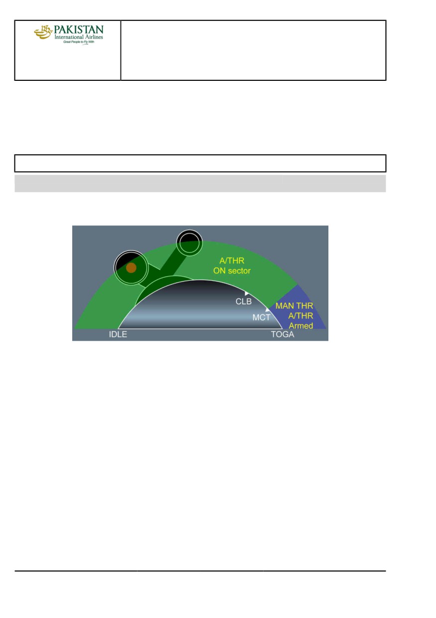
The above-noted principles also apply to an one-engine inoperative situation, except that A/THR can
only be active, when thrust levers are set between IDLE and MCT.
In case of engine failure, the thrust levers will be in MCT detent for remainder of the flight. This is
because MCT is the maximum thrust that can usually be commanded by the A/THR for climb or
acceleration, in all flight phases (e.g. CLB, CRZ, DES or APPR ).
With AP OFF, pilots may feel that the directional control is more difficult because the A/THR changes
the thrust setting. The choice between using, or not using A/THR after engine failure is a personal
one. As far as the speed control is concerned, the A/THR is usually more accurate than a pilot.
PIA A318/A319/A320/A321 FLEET
AS-FG-10-2 P 2/8
FCTM
← A to B
23 NOV 21
AIRCRAFT SYSTEMS
FLIGHT GUIDANCE
A318/A319/A320/A321
FLIGHT CREW
AUTOTHRUST
TECHNIQUES MANUAL
TO SET AUTOTHRUST TO OFF
Ident.: AS-FG-10-2-00018251.0002001 / 04 SEP 18
Applicable to: ALL
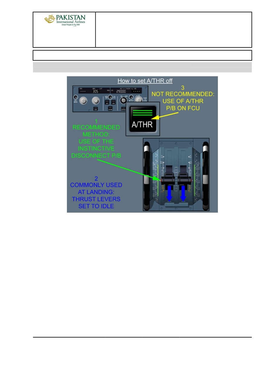
1) USE OF INSTINCTIVE DISCONNECT (I/D) PUSHBUTTON
If the I/D pb is pressed when the thrust levers are in CL detent, thrust will increase to MAX CL.
This will cause an unwanted thrust increase and may destabilize the approach.
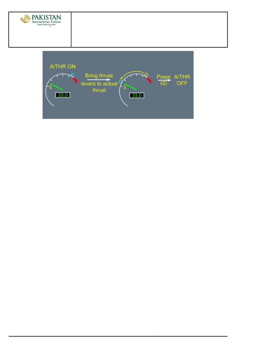
Therefore, the recommended technique for setting A/THR to off is:
- Return the thrust levers to approximately the current thrust setting, by observing the TLA symbol
on the thrust gauge
- Press the I/D pb.
This technique minimizes thrust discontinuity, when setting A/THR to off.
PIA A318/A319/A320/A321 FLEET
AS-FG-10-2 P 3/8
FCTM
C →
23 NOV 21
AIRCRAFT SYSTEMS
FLIGHT GUIDANCE
A318/A319/A320/A321
FLIGHT CREW
AUTOTHRUST
TECHNIQUES MANUAL
2) THRUST LEVERS SET TO IDLE
If thrust levers are set to IDLE, A/THR is set to off. This technique is usually used in descent, when
the A/THR is in THR IDLE, or at landing. During flare, with the A/THR active, the thrust levers
are set to the CLB detent. Then, when thrust reduction is required for landing, the thrust levers
should be moved rapidly and set to the IDLE stop. This will retard thrust, and set A/THR to off. As
a reminder, the "RETARD" aural alert will sound. In flare, this aural alert will occur at 20 ft, except
in the case of autoland, where it occurs at 10 ft.
It should be noted that, when the thrust levers are set back to IDLE and A/THR set to off: The
A/THR can be reactivated by pressing the pushbutton on the FCU, and returning the thrust levers
to the applicable detent. The thrust levers should be immediately returned to the applicable detent,
in order to avoid an ECAM "AUTO FLT A/THR LIMITED" alert.
3) USE OF THE A/THR PUSHBUTTON
Use of the A/THR pb is considered to be an involuntary A/THR off command (e.g. in the case of a
failure). When pressed, thrust is frozen and remains locked at the value it had when the flight crew
pressed the A/THR pb, as long as the thrust levers remain in the CLB or MCT detent.
If thrust levers are out of detent, thrust is manually controlled and, therefore, unlocked.
An ECAM caution and an FMA message trigger during thrust lock:
- THR LK appears on the FMA
- The AUTO FLT A/THR OFF ECAM alert is triggered
- The ENG THRUST LOCKED ECAM alert is triggered, if the thrust levers are not moved within
5 s.
In this case, when the flight crew moves the thrust levers out of detent, full manual control is
recovered, and the THR LK message disappears from the FMA.
This feature should not be used, unless the I/D pb are inoperative.
PIA A318/A319/A320/A321 FLEET
AS-FG-10-2 P 4/8
FCTM
← C
23 NOV 21
AIRCRAFT SYSTEMS
FLIGHT GUIDANCE
A318/A319/A320/A321
FLIGHT CREW
AUTOTHRUST
TECHNIQUES MANUAL
ALPHA FLOOR
Ident.: AS-FG-10-2-00018248.0001001 / 25 JUL 17
Applicable to: ALL
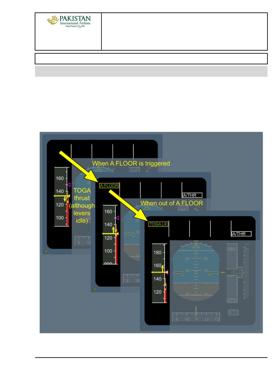
When the aircraft's angle-of-attack goes beyond the ALPHA FLOOR threshold, this means that the
aircraft has decelerated significantly (below ALPHA PROT speed): A/THR activates automatically
and orders TOGA thrust, regardless of the thrust lever position.
The example below illustrates that:
• The aircraft is in descent with the thrust levers manually set to IDLE.
• The aircraft decelerates, during manual flight with the FD off, as indicated on the FMA.
PIA A318/A319/A320/A321 FLEET
AS-FG-10-2 P 5/8
FCTM
D →
23 NOV 21
AIRCRAFT SYSTEMS
FLIGHT GUIDANCE
A318/A319/A320/A321
FLIGHT CREW
AUTOTHRUST
TECHNIQUES MANUAL
When the speed decreases, so that the angle-of-attack reaches the ALPHA FLOOR threshold,
A/THR activates and orders TOGA thrust, despite the fact that the thrust levers are at IDLE.
When the aircraft accelerates again, the angle-of-attack drops below the ALPHA FLOOR threshold.
TOGA thrust is maintained or locked. This enables the flight crew to reduce thrust, as necessary.
TOGA LK appears on the FMA to indicate that TOGA thrust is locked. The desired thrust can only be
recovered by setting A/THR to off, with the instinctive disconnect pushbutton.
ALPHA floor is available, when the flight controls are in NORMAL LAW, from liftoff to 100 ft RA at
landing. It is inhibited in some cases of engine failure.
AUTOTHRUST USE - SUMMARY
Ident.: AS-FG-10-2-00018253.0001001 / 20 MAR 17
Applicable to: ALL
Use of A/THR is recommended during the entire flight.
It may be used in most failures cases, including:
- Engine failure, even during autoland
- Abnormal configurations.
PIA A318/A319/A320/A321 FLEET
AS-FG-10-2 P 6/8
FCTM
← D to E →
23 NOV 21
AIRCRAFT SYSTEMS
FLIGHT GUIDANCE
A318/A319/A320/A321
FLIGHT CREW
AUTOTHRUST
TECHNIQUES MANUAL
A/THR should be monitored via the:
- FMA - SPEED / SPEED TREND on the PFD
- N1/N1 command (EPR) on the ECAM E/WD.
PIA A318/A319/A320/A321 FLEET
AS-FG-10-2 P 7/8
FCTM
← E
23 NOV 21
AIRCRAFT SYSTEMS
FLIGHT GUIDANCE
A318/A319/A320/A321
FLIGHT CREW
AUTOTHRUST
TECHNIQUES MANUAL
Intentionally left blank
PIA A318/A319/A320/A321 FLEET
AS-FG-10-2 P 8/8
FCTM
23 NOV 21
AIRCRAFT SYSTEMS
FLIGHT MANAGEMENT
A318/A319/A320/A321
FLIGHT CREW
USE OF FMS
TECHNIQUES MANUAL
NAVIGATION ACCURACY
Ident.: AS-FM-10-00019557.0001001 / 25 JUL 17
Applicable to: ALL
NAVIGATION ACCURACY CROSSCHECK TECHNIQUE
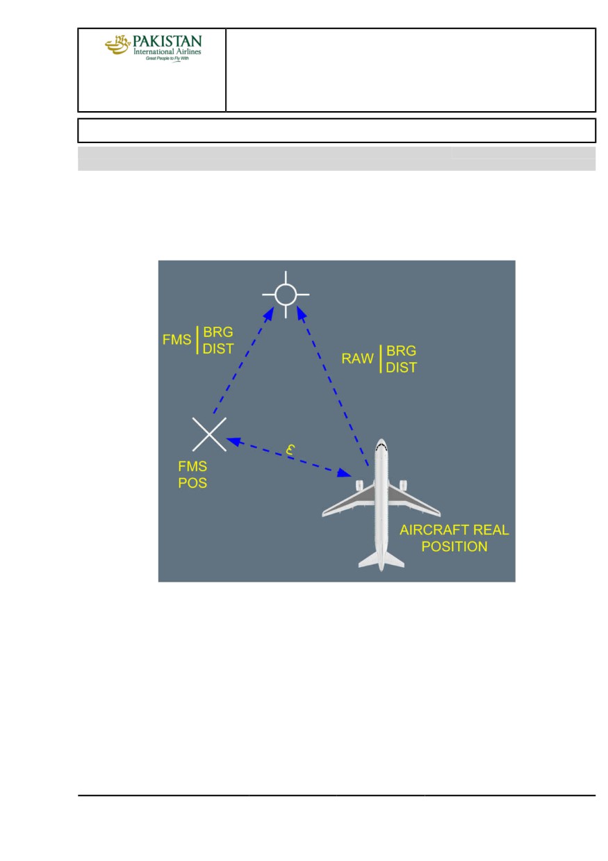
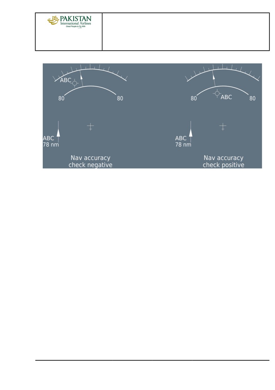
The principle consists in comparing the FMS position with the RADIO position (aircraft real
position).
Navigation Accuracy Crosscheck
The flight crew inserts a radio ident in MCDU PROG page (which provides a bearing/distance
relative to FMS position). Then, the flight crew compares these values with raw data received from
the NAVAID that indicates the real position of the aircraft . This enables to quantify the error ε.
PIA A318/A319/A320/A321 FLEET
AS-FM-10 P 1/12
FCTM
A →
12 JAN 22
AIRCRAFT SYSTEMS
FLIGHT MANAGEMENT
A318/A319/A320/A321
FLIGHT CREW
USE OF FMS
TECHNIQUES MANUAL
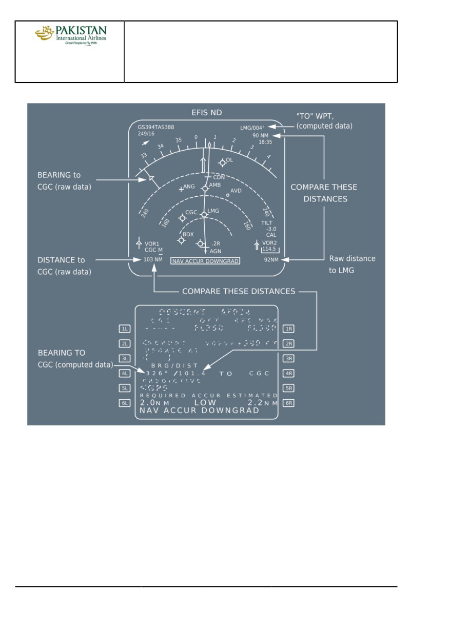
Navigation Accuracy Crosscheck Technique
On the ND, the flight crew compares the position of the needle and its associated DME distance
(the real position of the aircraft) with the position of the NAVAID symbol and its associated
distance, indicated by the range markers (these markers provide a bearing/distance, in relation to
the FMS position).
PIA A318/A319/A320/A321 FLEET
AS-FM-10 P 2/12
FCTM
← A →
12 JAN 22
AIRCRAFT SYSTEMS
FLIGHT MANAGEMENT
A318/A319/A320/A321
FLIGHT CREW
USE OF FMS
TECHNIQUES MANUAL
Navigation Accuracy Crosscheck Technique on the ND
POSITION UPDATE
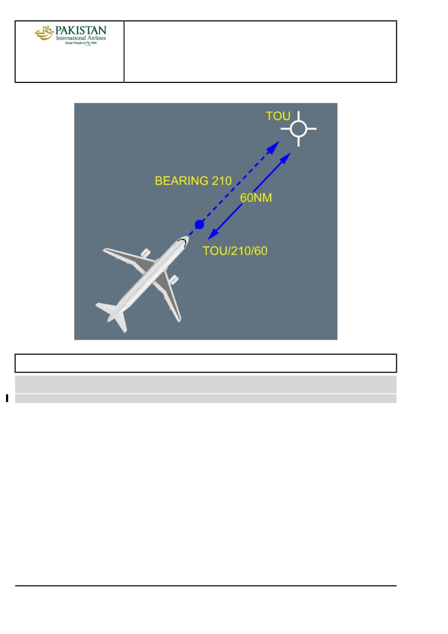
In case of an obvious and major map shift noticed by specific messages such as "CHECK A/C
POSITION, FM1/FM2 POS MISMATCH", the aircraft position may be updated on the MCDU
PROG page. Two techniques are available:
The recommended technique is to carry out a FMS update over a beacon by pressing the
UPDATE prompt once estimating that the aircraft overflies the beacon using the associated
needle. The potential error induced is approximately 4 to 5 NM. When the position update is
achieved, the EPE is automatically set to a higher value and the navigation accuracy is low.
The second technique consists in updating the FM position when flying over a
Point/Bearing/Distance (P/B/D) with reference to beacon raw data (Needle + Distance) rather than
the beacon itself. The potential for error is far less when the distance is greater than 60 NM. The
flight crew will keep in mind the potential 180 ° error on bearing.
PIA A318/A319/A320/A321 FLEET
AS-FM-10 P 3/12
FCTM
← A →
12 JAN 22
AIRCRAFT SYSTEMS
FLIGHT MANAGEMENT
A318/A319/A320/A321
FLIGHT CREW
USE OF FMS
TECHNIQUES MANUAL
FM Position Update in Flight
ZFW - ZFWCG ENTRY ERRORS
Ident.: AS-FM-10-A-00019558.0002001 / 20 MAR 17
Criteria: J3283, P8572, SA
1 Applicable to: MSN 05746-07792
GENERAL
The aircraft Gross Weight (GW) and Centre of Gravity (CG) are computed independently by the
FM and FAC:
- GW and CG values FM computed are used for:
• FM predictions and speeds
• ECAM (GW)
• MCDU (GW and CG)
• Computation of characteristic speeds (VLS, F, S, GD) for display on PFD
- GW and CG values FAC computed are used for:
• Flight control laws
A ZFW or ZFWCG entry error in MCDU INIT B page induces calculation errors that are to be
highlighted.
PIA A318/A319/A320/A321 FLEET
AS-FM-10 P 4/12
FCTM
← A to B →
12 JAN 22
AIRCRAFT SYSTEMS
FLIGHT MANAGEMENT
A318/A319/A320/A321
FLIGHT CREW
USE OF FMS
TECHNIQUES MANUAL
Ident.: AS-FM-10-A-00019558.0001001 / 20 MAR 17
Criteria: SA
2 Applicable to: MSN 02155-05253
GENERAL
The aircraft Gross Weight (GW) and Centre of Gravity (CG) are computed independently by the
FM and FAC:
- GW and CG values FM computed are used for:
• FM predictions and speeds
• ECAM (GW)
• MCDU (GW and CG).
- GW and CG values FAC computed are used for:
• Flight control laws
• Computation of characteristic speeds (VLS, F, S, GD) for display on PFD.
A ZFW or ZFWCG entry error in MCDU INIT B page induces calculation errors that are to be
highlighted.
Ident.: AS-FM-10-A-00019559.0002001 / 11 MAY 21
Criteria: J3283, J3438, P8572, SA
3 Applicable to: MSN 05746-07792
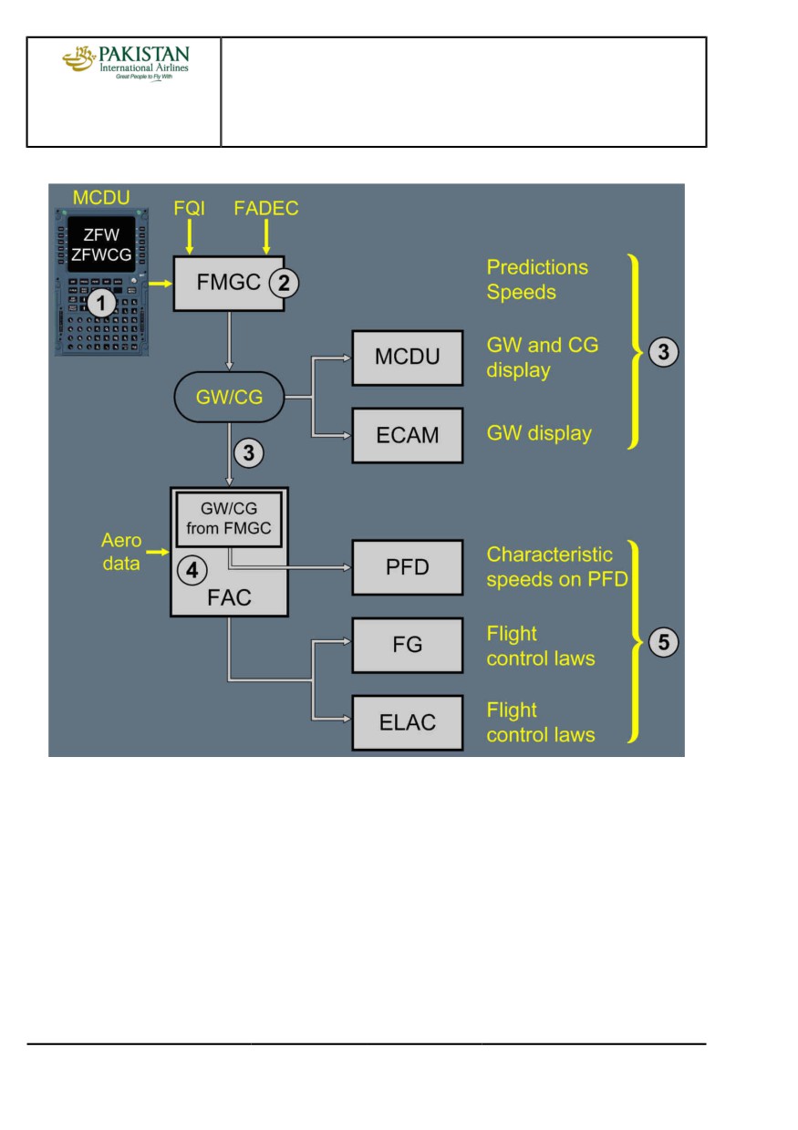
TECHNICAL BACKGROUND
The GW and CG computation is as follows:
1. The flight crew enters the ZFW and ZFWCG in the INIT B page.
2. The FMGC computes the GW and CG from:
- The ZFW, ZFWCG inserted in the INIT B page
- The fuel quantities from the FQI
- The Fuel Flow from the FADEC.
3. This current GW and/or CG is used:
- For FM predictions and speeds
- For ECAM display (GW only)
- For MCDU (GW and CG)
- By FAC for characteristic speed computation for PFD.
4. The FAC computes its own GW and CG from aerodynamic data.
5. GW and CG FAC computed are used for minor adjustments on the flight control laws.
PIA A318/A319/A320/A321 FLEET
AS-FM-10 P 5/12
FCTM
← B →
12 JAN 22
AIRCRAFT SYSTEMS
FLIGHT MANAGEMENT
A318/A319/A320/A321
FLIGHT CREW
USE OF FMS
TECHNIQUES MANUAL
GW and CG Computation and Use
Note:
- On ground, FAC uses the GW FM computed.
- In flight, at low altitude (below 14 625 ft), low speed (below 250 kt) and flight
parameters stabilized, GW FAC computed comes from aerodynamic data. If these
conditions are not met, GW FAC computed equates to the last memorized GW minus
fuel used.
- If the GW FM computed and FAC computed differs from a given threshold, a CHECK
GW message appears on the MCDU scratchpad.
PIA A318/A319/A320/A321 FLEET
AS-FM-10 P 6/12
FCTM
← B →
12 JAN 22
AIRCRAFT SYSTEMS
FLIGHT MANAGEMENT
A318/A319/A320/A321
FLIGHT CREW
USE OF FMS
TECHNIQUES MANUAL
Ident.: AS-FM-10-A-00019559.0001001 / 11 MAY 21
Criteria: SA
4 Applicable to: MSN 02155-05253
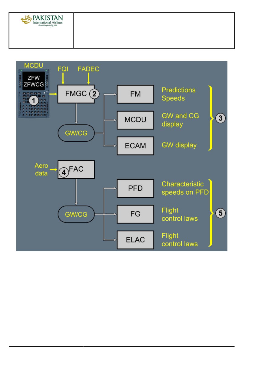
TECHNICAL BACKGROUND
The GW and CG computation is as follows:
1. The flight crew enters the ZFW and ZFWCG in the INIT B page.
2. The FMGC computes the GW and CG from:
- The ZFW, ZFWCG inserted in the INIT B page
- The fuel quantities from the FQI
- The Fuel Flow from the FADEC.
3. This current GW and/or CG is used for:
- FM predictions and speeds
- ECAM (GW only)
- MCDU (GW and CG).
4. The FAC computes its own GW and CG from aerodynamic data.
5. GW and CG FAC computed are used for:
- Minor adjustments on the flight control laws
- Characteristic speeds (VLS, F, S, Green dot) display on PFD.
PIA A318/A319/A320/A321 FLEET
AS-FM-10 P 7/12
FCTM
← B →
12 JAN 22
AIRCRAFT SYSTEMS
FLIGHT MANAGEMENT
A318/A319/A320/A321
FLIGHT CREW
USE OF FMS
TECHNIQUES MANUAL
GW and CG Computation and Use
Note:
- On ground, FAC uses the GW FM computed.
- In flight, at low altitude (below 14 625 ft), low speed (below 250 kt) and flight
parameters stabilized, GW FAC computed comes from aerodynamic data. If these
conditions are not met, GW FAC computed equates to the last memorized GW minus
fuel used.
- If the GW FM computed and FAC computed differs from a given threshold, a CHECK
GW message appears on the MCDU scratchpad.
PIA A318/A319/A320/A321 FLEET
AS-FM-10 P 8/12
FCTM
← B →
12 JAN 22
AIRCRAFT SYSTEMS
FLIGHT MANAGEMENT
A318/A319/A320/A321
FLIGHT CREW
USE OF FMS
TECHNIQUES MANUAL
Ident.: AS-FM-10-A-00019560.0002001 / 20 MAR 17
Criteria: J3283, J3438, P8572, SA
5 Applicable to: MSN 05746-07792
ZFW ENTRY ERROR AND OPERATIONAL CONSEQUENCES
If the pilot enters erroneous ZFW on MCDU INIT B page, this will affect as follows:
- GW and, to a lesser degree, CG, computed by FM are erroneous. This induces the following
consequences:
• The FM predictions and speeds are erroneous
• Incorrect GW and CG on MCDU FUEL PRED page
• Incorrect GW displayed on ECAM
• Characteristic speeds on PFD are erroneous
• SRS mode guidance is affected if computed VLS is above V2 as inserted in the MCDU PERF
TAKE-OFF page.
- GW FAC computed, which is based on GW FM computed on ground, will be updated only once
airborne through a specific slow calculation using AOA information.
Note:
1. In flight, if the FM and FAC GW differ from a given threshold, a "CHECK GW"
message is triggered on the MCDU.
2. Valpha prot, Vaalpha max, Vsw are not affected since based on aerodynamic data.
ERRONEOUS FUEL ON BOARD ENTRY
As long as the engines are not started, the FM GW is erroneous and above-mentioned
consequences apply. Once the engines are started, the fuel figures are updated and
downstream data update accordingly.
It should be noted however, that the FOB on ECAM is correct since it is provided from FQI data.
PIA A318/A319/A320/A321 FLEET
AS-FM-10 P 9/12
FCTM
← B →
12 JAN 22
AIRCRAFT SYSTEMS
FLIGHT MANAGEMENT
A318/A319/A320/A321
FLIGHT CREW
USE OF FMS
TECHNIQUES MANUAL
Ident.: AS-FM-10-A-00019560.0001001 / 20 MAR 17
Criteria: SA
6 Applicable to: MSN 02155-05253
ZFW ENTRY ERROR AND OPERATIONAL CONSEQUENCES
If the pilot enters erroneous ZFW on MCDU INIT B page, this will affect as follows:
- GW and, to a lesser degree, CG, computed by FM are erroneous. This induces the following
consequences:
• The FM predictions and speeds are erroneous
• Incorrect GW and CG on MCDU FUEL PRED page
• Incorrect GW displayed on ECAM
- FAC GW, which is based on FM GW on ground, will be updated only once airborne through a
specific slow calculation using AOA information. Consequently,
• Characteristic speeds on PFD at take-off are erroneous, but they are correct in flight
• SRS mode guidance is affected if computed VLS is above V2 as inserted in the MCDU PERF
TAKE-OFF page.
Note:
1. In flight, if the FM and FAC GW differ from a given threshold, a "CHECK GW"
message is triggered on the MCDU.
2. Valpha prot, Valpha max, Vsw are not affected since based on aerodynamic data.
ERRONEOUS FUEL ON BOARD ENTRY
As long as the engines are not started, the FM GW is erroneous and above-mentioned
consequences apply. Once the engines are started, the fuel figures are updated and
downstream data update accordingly.
It should be noted however, that the FOB on ECAM is correct since it is provided from FQI data.
Ident.: AS-FM-10-A-00019561.0002001 / 20 MAR 17
Criteria: J3283, J3438, P8572, SA
7 Applicable to: MSN 05746-07792
OPERATIONAL RECOMMENDATIONS
ZFW entries should be cross-checked by both crewmembers to avoid entry error.
If the "CHECK GW" amber warning is displayed on the MCDU, a discrepancy exists between the
FM computed GW and the FAC computed GW.
The crew will compare the Load and Trim Sheet (LTS) figures with the FM GW and fuel used:
- If an obvious entry error is detected, FM GW will be updated on the MCDU FUEL PRED page.
- If FM and LTS GW are in accordance and appear to be correct, the FAC computed GW should
be suspected (AOA sensor problem).
- If FM and LTS GW are in accordance but LTS GW is suspected, characteristic speeds should
be extracted from QRH.
PIA A318/A319/A320/A321 FLEET
AS-FM-10 P 10/12
FCTM
← B →
12 JAN 22
AIRCRAFT SYSTEMS
FLIGHT MANAGEMENT
A318/A319/A320/A321
FLIGHT CREW
USE OF FMS
TECHNIQUES MANUAL
Ident.: AS-FM-10-A-00019561.0001001 / 20 MAR 17
Criteria: SA
8 Applicable to: MSN 02155-05253
OPERATIONAL RECOMMENDATIONS
ZFW entries should be cross-checked by both crewmembers to avoid entry error.
If the "CHECK GW" amber warning is displayed on the MCDU, a significant discrepancy exists
between the FM computed GW and the FAC computed GW.
The crew will compare the Load and Trim Sheet (LTS) figures with the FM GW and fuel used:
- If an obvious entry error is detected, FM GW will be updated on the MCDU FUEL PRED page.
- If FM and LTS GW are in accordance and appear to be correct, the FAC computed GW
should be suspected (AOA sensor problem). Consequently, characteristic speeds on PFD are
erroneous and should be disregarded. Characteristic speeds should be extracted from QRH.
- If FM and LTS GW are in accordance but LTS GW is suspected, FAC and QRH characteristic
speeds should be compared (to validate FAC outputs) and the most appropriate applied.
PIA A318/A319/A320/A321 FLEET
AS-FM-10 P 11/12
FCTM
← B
12 JAN 22
AIRCRAFT SYSTEMS
FLIGHT MANAGEMENT
A318/A319/A320/A321
FLIGHT CREW
USE OF FMS
TECHNIQUES MANUAL
Intentionally left blank
PIA A318/A319/A320/A321 FLEET
AS-FM-10 P 12/12
FCTM
12 JAN 22
AIRCRAFT SYSTEMS
RUDDER
A318/A319/A320/A321
FLIGHT CREW
TECHNIQUES MANUAL
GENERAL
Ident.: AS-RUD-00018204.0001001 / 20 MAR 17
Applicable to: ALL
In flight, the rudder controls the yaw, and the vertical stabilizer ensures directional stability. The
rudder and the vertical stabilizer are designed to :
- Provide sufficient lateral/directional control of the aircraft during crosswind takeoffs and landings,
within the certified crosswind limits
- Provide aircraft control in the case of an engine failure, and maximum asymmetric thrust at any
speed above the minimum control speed on ground (VMCG).
Flight crew controls the rudder via a conventional mechanical rudder control. FACs computers
provide:
- Yaw damping
- Rudder travel limitation.
Refer to FCOM/DSC-27-10-20 Yaw Control - General for more information about yaw control.
OPERATIONAL RECOMMENDATIONS
Ident.: AS-RUD-00018205.0002001 / 04 JUN 19
Applicable to: ALL
In order to avoid exceeding structural loads on the rudder and vertical stabilizer, the following
recommendations must be observed.
THE RUDDER IS DESIGNED TO CONTROL THE AIRCRAFT, IN THE FOLLOWING SITUATIONS
A. IN NORMAL OPERATIONS, FOR LATERAL CONTROL
- During takeoff roll, when on ground, particularly in crosswind conditions
- During landing flare with crosswind, for decrab purposes
- During the landing roll, when on the ground.
In the above situations, large and even rapid rudder inputs may be necessary in order to
maintain control of the aircraft.
The flight crew should always apply the rudder corrections as necessary, in order to obtain the
appropriate aircraft response.
On Airbus aircraft, the rudder control system includes a turn coordination function to achieve
acceptable turn coordination.
B. TO COUNTERACT THRUST ASYMMETRY
Up to full rudder deflection can be used to compensate for the yawing moments that are due to
asymmetric thrust.
PIA A318/A319/A320/A321 FLEET
AS-RUD P 1/2
FCTM
A to B →
04 SEP 19
AIRCRAFT SYSTEMS
RUDDER
A318/A319/A320/A321
FLIGHT CREW
TECHNIQUES MANUAL
Note:
At high speed (i.e. slats retracted), thrust asymmetry (eg. due to an engine failure)
does not have a significant effect on the yaw control of the aircraft. The rudder
deflection required to counter an engine failure and center the sideslip is small.
C. IN SOME OTHER ABNORMAL SITUATIONS
The flight crew may also use the rudder pedals in some abnormal situations. For example:
- Loss of both yaw damper systems. The flight crew uses the rudder pedals as deemed
necessary, for turn coordination to prevent excessive sideslip.
- Rudder trim runaway. The flight crew uses the rudder pedals in order to return the rudder to
neutral
- Landing with an abnormal landing gear position: The flight crew uses the rudder pedals for
directional control on the ground.
In all of the normal or abnormal situations that are described above, correct rudder pedals use
does not affect the structural integrity of the aircraft.
Note:
In the event of a rudder travel limit system failure, refer to the relevant RUDDER
TRAVEL LIMIT FAULT procedure.
The flight crew may use the rudder trim in case of failures leading to a permanent roll
asymmetry (e.g. G+B hydraulic failure) to alleviate permanent sidestick input.
THE RUDDER SHOULD NOT BE USED
- To induce roll
- To counter roll, induced by any type of turbulence.
Regardless of the airborne flight condition, aggressive, full or nearly full, opposite rudder pedal
inputs must not be applied. Such inputs can lead to loads higher than the limit, and can result in
structural damage or failure. The rudder travel limiter system is not designed to prevent structural
damage or failure in the event of such rudder system inputs.
For dutch roll, the flight control laws combined with the natural aircraft damping are sufficient to
correctly damp the dutch roll oscillations. Therefore, the flight crew should not use the rudder
pedals in order to complement the flight control laws.
STOP RUDDER INPUT AURAL ALERT
The "STOP RUDDER INPUT" aural alert and red PFD message associated with MASTER
WARNING light is triggered when inappropriate rudder inputs are detected. These alerts advise
the flight crew to avoid excessive rudder load. The flight crew should react and immediately
release the rudder pedals.
CAUTION
Avoid large and rapid rudder inputs.
PIA A318/A319/A320/A321 FLEET
AS-RUD P 2/2
FCTM
← B
04 SEP 19
AIRCRAFT SYSTEMS
TCAS
A318/A319/A320/A321
FLIGHT CREW
TECHNIQUES MANUAL
INTRUDER CLASSIFICATION
Ident.: AS-TCAS-00016287.0002001 / 26 NOV 19
Criteria: P11363, SA
Applicable to: MSN 07784-07792
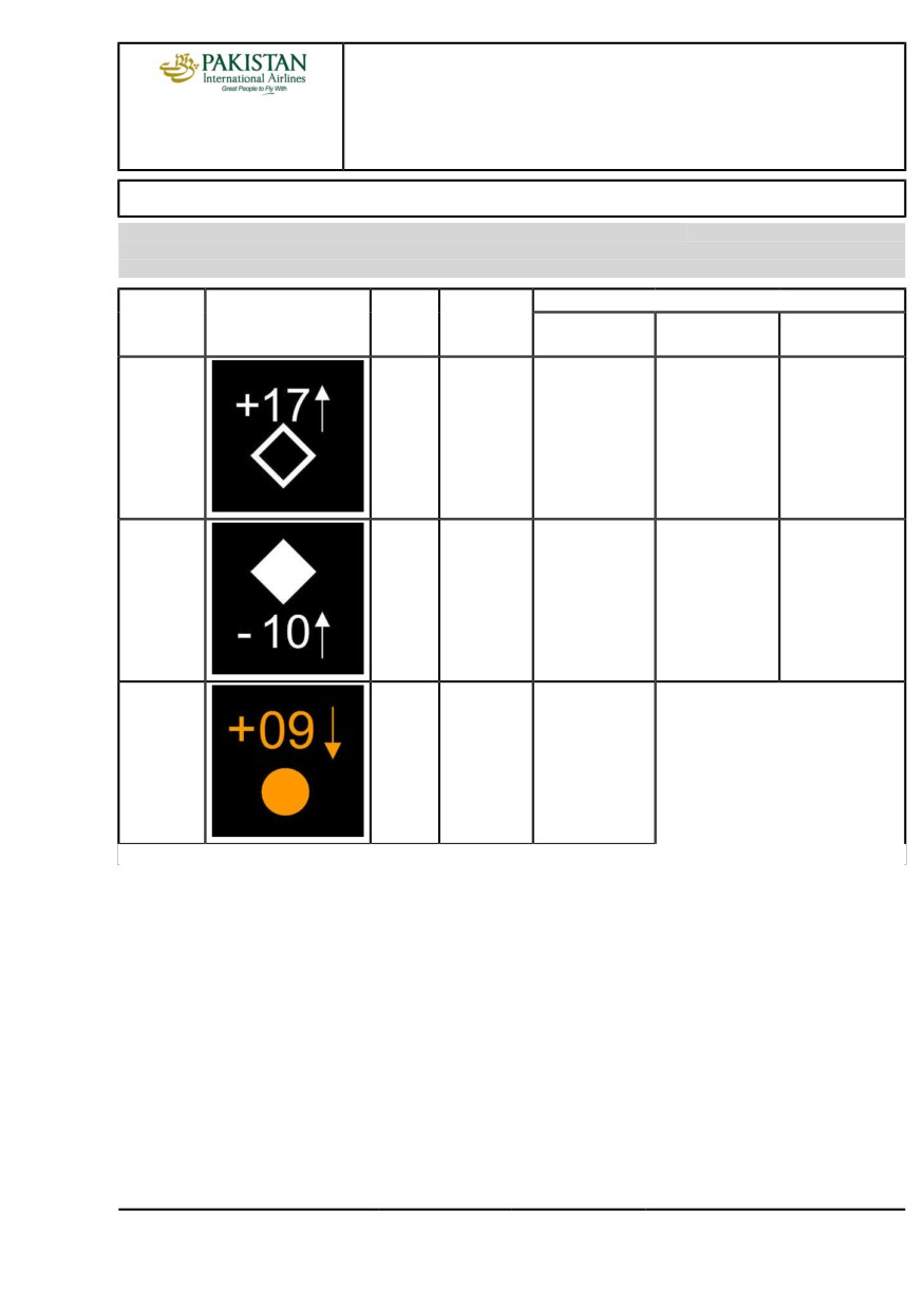
Type of
Flight crew response
Aural
Intruder
Display
collision
without
AP/FD TCAS
AP/FD TCAS
warning
threat
AP/FD TCAS
without AP
with AP
No threat
No threat
-
-
-
-
traffic or
others
Proximate
Consider
-
-
-
-
as No
threat
Traffic
Potential
"TRAFFIC
No evasive
Monitor AP/FD TCAS mode
Advisory
threat
TRAFFIC"
maneuver
arming. No evasive maneuver
(TA)
Continued on the following page
PIA A318/A319/A320/A321 FLEET
AS-TCAS P 1/8
FCTM
A →
12 JAN 22
AIRCRAFT SYSTEMS
TCAS
A318/A319/A320/A321
FLIGHT CREW
TECHNIQUES MANUAL
Continued from the previous page
Type of
Flight crew response
Aural
Intruder
Display
collision
without
AP/FD TCAS
AP/FD TCAS
warning
threat
AP/FD TCAS
without AP
with AP
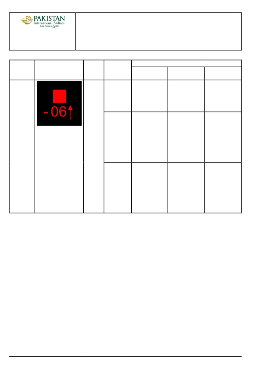
Resolution
Collision
Preventive,
Do not alter your
Follow the FDs.
Monitor V/S
Advisory
threat
e.g.
flight path and
Monitor V/S
remains out
(RA)
"MONITOR
keep VS out
remains out
of red area.
V/S"
of red sector
of red area.
(1)
(1)
Corrective,
Smoothly and
Smoothly
Monitor V/S gets
e.g. "CLIMB"
firmly (0.25 g)
and firmly
out of red area,
follow VSI green
follow the FDs.
and remains
sector within 5 s
Monitor V/S gets
in green area.
(1)
out of red area,
and remains
in green area.
(1)
Corrective,
Smoothly and
Smoothly
Monitor V/S gets
e.g. "CLIMB
firmly (0.35 g)
and firmly
out of red area,
NOW" or
follow VSI green
follow the FDs.
and remains
"INCREASE
sector within 2.5 s
Monitor V/S gets
in green area.
CLIMB"
out of red area,
(1)
and remains
in green area.
(1)
(1)
In AP/FD TCAS mode, the load factor authority of the guidance law is increased.
Note:
In some dynamic situation the TCAS may generate an RA without a previous TA. Such
situation is linked to a rapid change in the Intruder Detection Category.
PIA A318/A319/A320/A321 FLEET
AS-TCAS P 2/8
FCTM
← A →
12 JAN 22
AIRCRAFT SYSTEMS
TCAS
A318/A319/A320/A321
FLIGHT CREW
TECHNIQUES MANUAL
INTRUDER CLASSIFICATION
Ident.: AS-TCAS-00016287.0001001 / 26 NOV 19
Criteria: SA
1 Applicable to: MSN 02155-05746
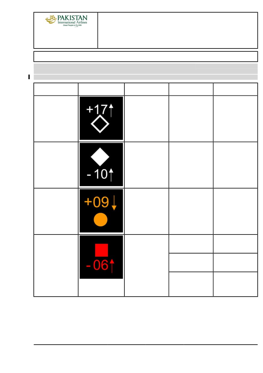
Type of
Intruder
Display
Aural warning
Crew action
collision threat
No threat
No threat
-
-
traffic or others
Proximate
Consider as No threat
-
-
Traffic Advisory (TA)
Potential threat
"TRAFFIC TRAFFIC"
No evasive maneuver
Resolution
Collision threat
Preventive, e.g.
Do not alter your
Advisory (RA)
"MONITOR V/S"
flight path and keep
VS out of red sector
Corrective,
Smoothly and firmly
e.g. "CLIMB"
(0.25 g) follow VSI
green sector within 5 s
Corrective, e.g.
Smoothly and
"CLIMB NOW" or
firmly (0.35 g)
"INCREASE CLIMB"
follow VSI green
sector within 2.5 s
Note:
In some dynamic situation the TCAS may generate an RA without a previous TA. Such
situation is linked to a rapid change in the Intruder Detection Category.
PIA A318/A319/A320/A321 FLEET
AS-TCAS P 3/8
FCTM
← A
12 JAN 22
AIRCRAFT SYSTEMS
TCAS
A318/A319/A320/A321
FLIGHT CREW
TECHNIQUES MANUAL
OPERATING TECHNIQUES
Ident.: AS-TCAS-10-00018674.0001001 / 16 JAN 18
2 Applicable to: MSN 02155-05746
ALL is the default selection. The flight crew may select another mode depending on the situation.
For more information, Refer to FCOM/DSC-34-SURV-60-20 ATC/TCAS Panel
TA shall be selected in the case of:
- Engine failure
- Known nearby traffic, which is in visual contact
- Flight with landing gear down
- Operations at specific airports, and during specific procedures that an operator identifies as
having a significant potential for not wanted and not appropriate RAs, e.g. closely spaced parallel
runways, converging runways.
The flight crew should comply with the vertical speed limitations during the last 2 000 ft of a climb
or descent. In particular, the flight crew should limit vertical speeds to 1 500 ft/min during the last
2 000 ft of a climb or descent, especially when they are aware of traffic that is converging in altitude
and intending to level off 1 000 ft above or below the flight crew's assigned altitude.
If a TA is generated:
- The PF announces: "TCAS, I have control".
- No evasive maneuver should be initiated, only on the basis of a TA.
If a RA is generated:
- The flight crew must always follow the TCAS RA orders in the correct direction, even:
• If the TCAS RA orders are in contradiction with the ATC instructions
• At the maximum ceiling altitude with CLIMB, CLIMB or INCREASE CLIMB, INCREASE CLIMB
TCAS RA orders
• If it results in crossing the altitude of the intruder.
CAUTION
If a pilot does not follow a RA, he should be aware that the intruder may be
TCAS equipped and may be maneuvering toward his aircraft in response to a
coordinated RA. This could compromize safe separation.
- The PF disconnects the AP, and smoothly and firmly follows the Vertical Speed Indicator (VSI)
green sector within 5 s, and requests that both FDs be disconnected.
Note:
Both FDs must be disconnected once APs are disconnected:
- To ensure autothrust speed mode
- To avoid possible confusion between FD bar orders and, TCAS aural and VSI orders
- The PM disconnects both FDs, but will not try to see intruders.
PIA A318/A319/A320/A321 FLEET
AS-TCAS P 4/8
FCTM
B →
12 JAN 22
AIRCRAFT SYSTEMS
TCAS
A318/A319/A320/A321
FLIGHT CREW
TECHNIQUES MANUAL
- The PF will avoid excessive maneuvers, and keep the Vertical Speed outside the red area of the
VSI and within the green area. If necessary, the PF must use the full speed range between Valpha
max and Vmax.
- The PM must notify ATC.
- The flight crew should never maneuver in the opposite direction of the RA, because TCAS
maneuvers are coordinated.
- In final approach, i.e. "CLIMB", "CLIMB NOW", "INCREASE CLIMB", the flight crew will initiate a
go-around.
When clear of conflict:
- The flight crew must resume normal navigation, in accordance with ATC clearance, and using the
AP, as required.
Ident.: AS-TCAS-10-00016288.0002001 / 16 JAN 18
Applicable to: MSN 07784-07792
ALL is the default selection. The flight crew may select another mode depending on the situation.
For more information, Refer to FCOM/DSC-34-SURV-60-20 ATC/TCAS Panel
TA shall be selected in the case of:
- Engine failure
- Known nearby traffic, which is in visual contact
- Flight with landing gear down
- Operations at specific airports, and during specific procedures that an operator identifies as
having a significant potential for not wanted and not appropriate RAs, e.g. closely spaced parallel
runways, converging runways.
Note:
If TA is selected (TA ONLY mode), the AP/FD TCAS mode will not arm.
The flight crew should comply with the vertical speed limitations during the last 2 000 ft of a climb
or descent. In particular, the flight crew should limit vertical speeds to 1 500 ft/min during the last
2 000 ft of a climb or descent, especially when they are aware of traffic that is converging in altitude
and intending to level off 1 000 ft above or below the flight crew's assigned altitude.
USE OF AP/FD TCAS MODE
When the AP/FD TCAS mode is available, the flight crew should use the AP/FD TCAS mode. In
the case the AP/FD TCAS mode is not available (e.g. the AP/FD mode is failed or the aircraft is
not equipped with the AP/FD TCAS mode) the flight crew must apply the "TCAS procedure without
AP/FD TCAS" See chapter "TCAS Procedure without AP/FD TCAS".
TRAFFIC ADVISORY (TA)
If a TA is triggered, the flight crew should check the immediate arming of the AP/FD TCAS mode,
and the engagement status of the AP and A/THR.
TCAS in blue on the FMA indicates that the AP/FD TCAS mode is available, and armed.
PIA A318/A319/A320/A321 FLEET
AS-TCAS P 5/8
FCTM
← B →
12 JAN 22
AIRCRAFT SYSTEMS
TCAS
A318/A319/A320/A321
FLIGHT CREW
TECHNIQUES MANUAL
If a TA is generated:
- The PF announces "TCAS blue" .
- If the A/THR is off, the PF should request the PM to set it ON
- The PF must not initiate an evasive maneuver, only on the basis of a TA
Note:
If the AP/FD TCAS mode does not immediately arm, the AP/FD TCAS mode is
failed or the aircraft is not equipped with the AP/FD TCAS mode. In that case,
the PF announces "TCAS, I have control" and the flight crew must be prepared to
manually follow the Resolution Advisory orders, in the case of a subsequent RA.
See chapter "TCAS Procedure without AP/FD TCAS".
RESOLUTION ADVISORY (RA)
If a RA is generated:
• The flight crew must always follow the TCAS RA orders in the correct direction, even:
- If the TCAS RA orders are in contradiction with the ATC instructions
- At the maximum ceiling altitude with "CLIMB, CLIMB" or "INCREASE CLIMB, INCREASE
CLIMB" TCAS RA orders
- If it results in crossing the altitude of the intruder.
CAUTION
If a pilot does not follow a RA, he should be aware that the intruder may be
TCAS equipped and may be maneuvering toward his aircraft in response to
a coordinated RA. This could compromize safe separation.
AP/FD TCAS MODE ENGAGEMENT
If an RA is triggered, the AP/FD TCAS mode automatically, and immediately, engages.
The PF announces the AP/FD TCAS mode engagement, like any other FMA changes.
If the FDs are disengaged, they automatically engage. The FD pitch bar does not flash, and
the triple click aural alert does not sound, in order to avoid to disturb the PF during the evasive
maneuver.
If the A/THR is disconnected, it automatically becomes armed or active.
If APs and FDs are OFF when the RA is triggered, HDG automatically engages.
TCAS PROCEDURE WITH AP/FD TCAS
If an RA is triggered:
- If the AP is engaged, the PF should keep it ON
The AP guides the aircraft in accordance with the RA orders.
- If the AP is not engaged:
• The PF smoothly and firmly flies the FD pitch bar
The FD orders guide the aircraft in accordance with the RA orders
• The PF can ask the PM to engage the AP.
PIA A318/A319/A320/A321 FLEET
AS-TCAS P 6/8
FCTM
← B →
12 JAN 22
AIRCRAFT SYSTEMS
TCAS
A318/A319/A320/A321
FLIGHT CREW
TECHNIQUES MANUAL
-
The PM monitors the evasive maneuver. He does not try to see the reported traffic.
The flight crew checks that the guidance of AP/FD TCAS mode leads the vertical speed out of
the red area of the vertical speed scale, and in the green area if any.
CAUTION
If for any reason during an RA, the aircraft vertical speed does not reach the
green area of the vertical speed scale, the PF should disconnect the AP, and
override the FD orders, in order to lead the aircraft vertical speed out of the
red area of the vertical speed scale.
If necessary, the PF must use the full speed range between Vαmax and
Vmax.
-
If any "CLIMB" aural alert sounds during the final approach, the flight crew should first apply
the AP/FD TCAS procedure. When clear of conflict, depending on the situation, they can
consider a go-around.
-
The PM notifies the ATC
-
When clear of conflict:
• The AP/FD TCAS mode automatically reverts to V/S, in order to capture the FCU selected
altitude. In some cases, the AP/FD TCAS mode may revert to an altitude acquire mode, or
an altitude hold mode.
• The PM notifies the ATC
• The PF engages an appropriate vertical mode, or adjusts the vertical speed target, in
accordance with ATC clearance.
Note:
The AP/FD TCAS mode is speed protected, i.e. it ensures that the aircraft speed
remains between VLS- 5 kt and Vmax. Therefore, in the case the RA is triggered when
the aircraft is close to its performance limits, the RA vertical speed target may not be
reached with the AP/FD TCAS mode.
TCAS PROCEDURE WITHOUT AP/FD TCAS
If a RA is generated and the TCAS flight guidance mode is not available:
- The PF disconnects the AP, and smoothly and firmly follows the Vertical Speed Indicator
(VSI) green sector within 5 s, and requests that both FDs be disconnected.
Note:
Both FDs must be disconnected once APs are disconnected:
• To ensure autothrust speed mode
• To avoid possible confusion between FD bar orders and, TCAS aural and VSI
orders
- The PM disconnects both FDs, but will not try to see intruders.
- The PF will avoid excessive maneuvers, and keep the Vertical Speed outside the red area
of the VSI and within the green area. If necessary, the PF must use the full speed range
between Valpha max and Vmax.
PIA A318/A319/A320/A321 FLEET
AS-TCAS P 7/8
FCTM
← B →
12 JAN 22
AIRCRAFT SYSTEMS
TCAS
A318/A319/A320/A321
FLIGHT CREW
TECHNIQUES MANUAL
- The PM must notify ATC.
- The flight crew should never maneuver in the opposite direction of the RA, because TCAS
maneuvers are coordinated.
- In final approach, i.e. "CLIMB", "CLIMB NOW", "INCREASE CLIMB", the flight crew will
initiate a go-around.
- When clear of conflict, the flight crew must resume normal navigation, in accordance with
ATC clearance, and using the AP, as required.
PIA A318/A319/A320/A321 FLEET
AS-TCAS P 8/8
FCTM
← B
12 JAN 22
AIRCRAFT SYSTEMS
WEATHER RADAR
A318/A319/A320/A321
FLIGHT CREW
TECHNIQUES MANUAL
GENERAL
Ident.: AS-WXR-00019761.0001001 / 20 MAR 17
Applicable to: ALL
This FCTM chapter provides basic knowledge on the use of onboard weather radars. To get all the
information on the characteristics, limitations and operational recommendations of each radar, refer
to the user guide of the radar manufacturer.
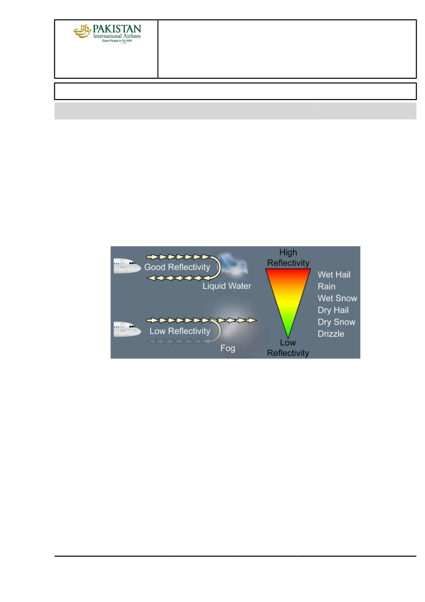
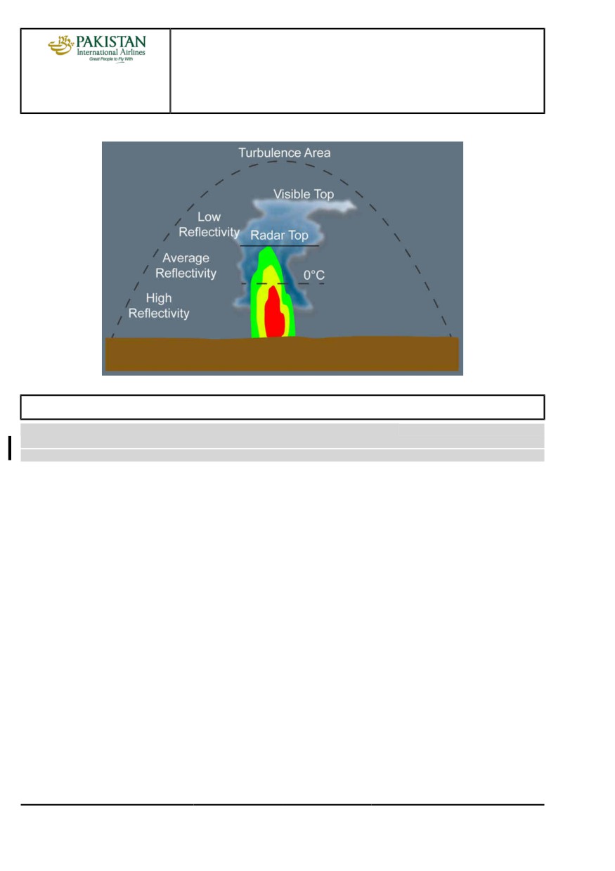
Weather detection is based on the reflectivity of water droplets. The weather echo appears on the
ND with a color scale that goes from red (high reflectivity) to green (low reflectivity).
The intensity of the weather echo is associated with the droplet size, composition and quantity (e.g.
the reflectivity of a water particle is five times more than an ice particle of the same size). The flight
crew must be aware that the weather radar does not detect weather that has small droplets (e.g.
clouds or fog), or that does not have droplets (e.g. clear air turbulence).
Weather Radar Principle
The purpose of the weather radar is to help the flight crew detect and avoid storm cells (e.g.
cumulonimbus). Due to its large vertical expansion, a storm cell does not have the same reflectivity
depending on the altitude. The quantity of liquid water in the atmosphere decreases with the altitude.
Therefore the reflectivity of a storm cell decreases with the altitude.
The upper detection limit of the weather radar is called the radar top.
The flight crew must be aware of both of the following:
- The radar top is not the visible top of the storm cell
- The storm cell and associated turbulence extend significantly above the radar top.
PIA A318/A319/A320/A321 FLEET
AS-WXR P 1/20
FCTM
A →
12 JAN 22
AIRCRAFT SYSTEMS
WEATHER RADAR
A318/A319/A320/A321
FLIGHT CREW
TECHNIQUES MANUAL
Reflective Image of a Cumulonimbus
WEATHER DETECTION
Ident.: AS-WXR-00019763.0005001 / 20 MAR 17
Criteria: 34-1530, P11935, SA
1 Applicable to: MSN 04392-05746
The flight crew uses the following controls and functions to operate the weather radar:
- DISPLAY MODE
- GAIN
- RANGE.
STANDARD DISPLAY MODE
The flight crew should use the ALL WX display mode as a default mode for the weather radar. In
addition, the flight crew should check the weather for several ND ranges in order to identify the
strongest weather returns.
GAIN SETTING FOR WEATHER DETECTION
The flight crew should use the calibrated gain (CAL or AUTO) for weather detection as a default
mode for the weather radar. The use of the calibrated gain ensures a standard display of the
colors on the ND. The flight crew can manually tune the gain to analyze storm cells. .Refer to
AS-WXR Analysis of weather radar data
PIA A318/A319/A320/A321 FLEET
AS-WXR P 2/20
FCTM
← A to B →
12 JAN 22
AIRCRAFT SYSTEMS
WEATHER RADAR
A318/A319/A320/A321
FLIGHT CREW
TECHNIQUES MANUAL
RANGE MANAGEMENT
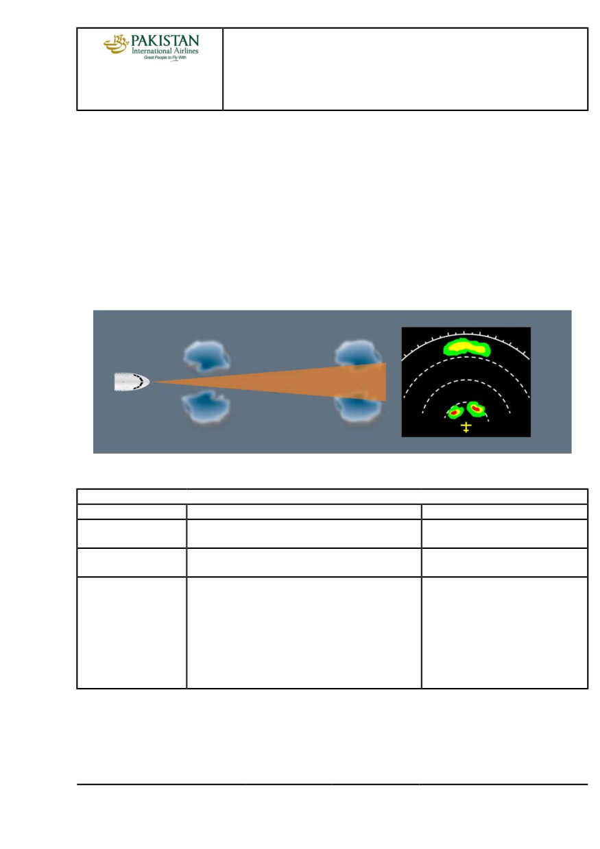
The flight crew should monitor both the long-distance and short-distance weather, in order to be
able to efficiently plan appropriate course changes, and to avoid the “blind alley effect". Refer to
AS-WXR Analysis of weather radar data
At long distance ahead of the aircraft, the accuracy of the weather displayed is low, due to both of
the following:
- The increase in the width of the weather radar beam
- Signal attenuation.
Therefore, the accuracy of the weather displayed is better for short-distance weather.
Accuracy of the Weather Display
USE OF THE WEATHER RADAR IN ACCORDANCE WITH THE FLIGHT PHASE
RDR-4000
Flight Phase
Recommended Setting
Comments
Set the weather radar sw to ON during taxi.
30 s are necessary for the 3D buffer of
TAXI
the radar to be filled.
Select the ALL display mode.
When lined up, check of the departure
TAKEOFF
path.
Adjust the ND range as required.
In cruise, the combination of the
Use the ALL display mode.
following ND ranges provides good
Switch to ON PATH (PATH WX) or to manual ELEVN
weather awareness:
mode for storm cell analysis, and then set back to ALL.
IN FLIGHT
-
160 NM on the PM ND
-
80 NM on the PF ND.
Use shorter ND ranges to track/avoid
short-distance weather.
PIA A318/A319/A320/A321 FLEET
AS-WXR P 3/20
FCTM
← B →
12 JAN 22
AIRCRAFT SYSTEMS
WEATHER RADAR
A318/A319/A320/A321
FLIGHT CREW
TECHNIQUES MANUAL
WEATHER DETECTION
Ident.: AS-WXR-00019763.0001001 / 20 MAR 17
Criteria: SA
Applicable to: MSN 02155-03097, 07784-07792
The flight crew uses the following controls and functions to operate the weather radar:
- TILT
- GAIN
- RANGE.
MANUAL TILT MANAGEMENT
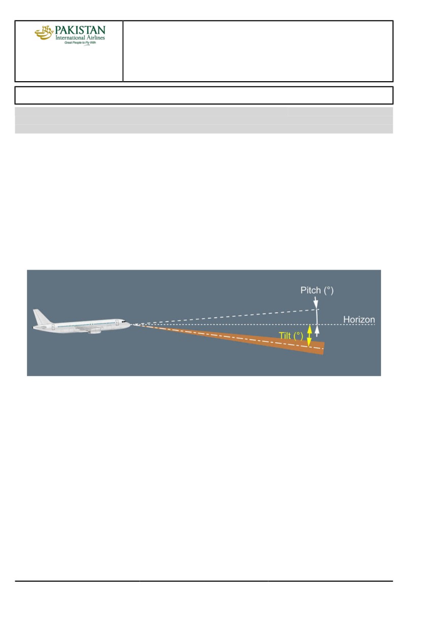
The tilt refers to the angle between the antenna beam centerline and the horizon.
The radar uses data from the IRS to stabilize its antenna. Therefore, the antenna tilt is
independent of the aircraft pitch and bank angle.
Tilt Angle Definition
The flight crew should regularly scan the area ahead of the aircraft, at several ND ranges. In order
to identify the strongest weather returns, the flight crew should tilt the weather radar antenna up
and down.
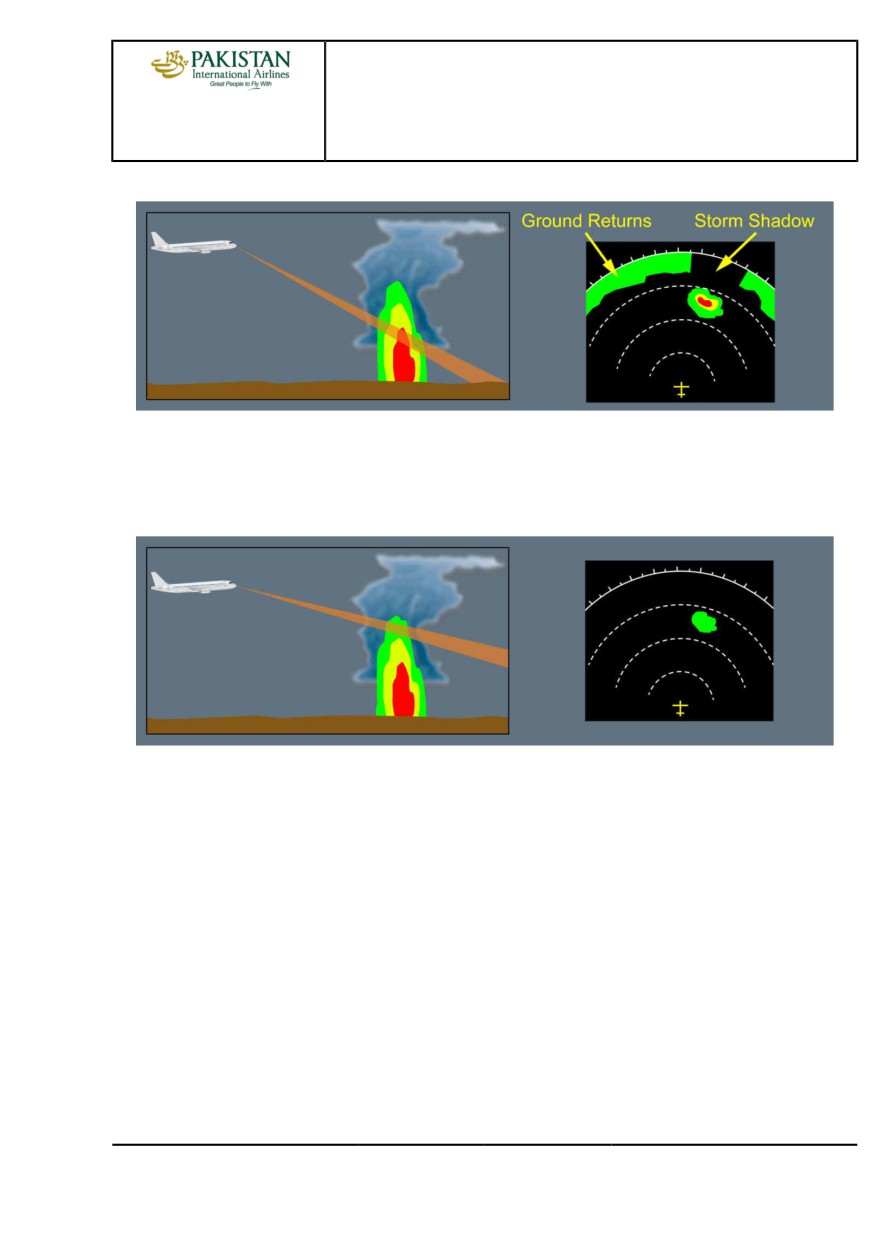
To obtain a correct display of a storm cell, the flight crew must use the tilt knob to point the
weather radar beam to the most reflective part of the storm cell. A correct tilt setting prevents the
overscanning of the storm cell.
Note:
Common practice is to ensure that the ground return is at the top of the ND screen.
PIA A318/A319/A320/A321 FLEET
AS-WXR P 4/20
FCTM
← B →
12 JAN 22
AIRCRAFT SYSTEMS
WEATHER RADAR
A318/A319/A320/A321
FLIGHT CREW
TECHNIQUES MANUAL
Correct Storm Display
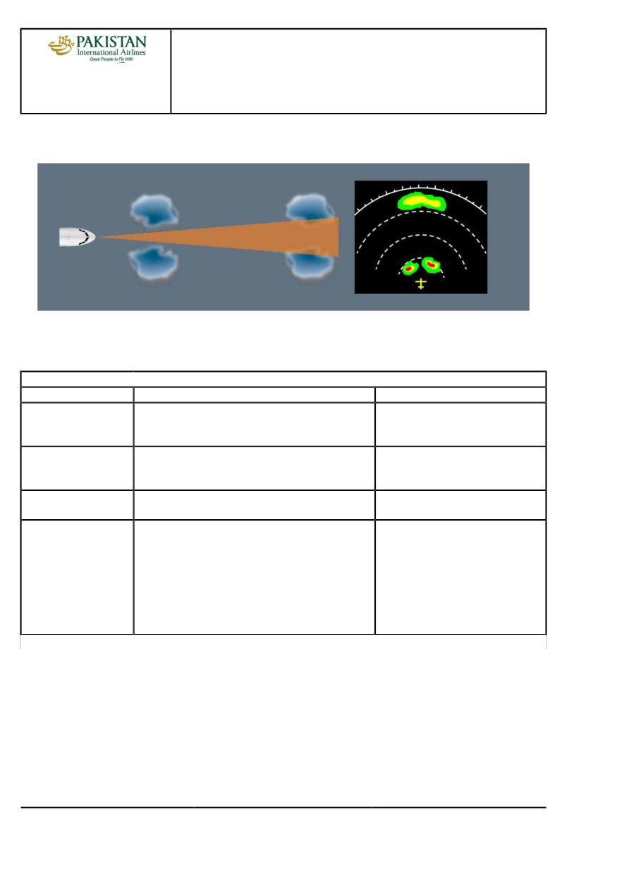
At high altitude, a storm cell may contain ice particles that have low reflectivity. If the tilt setting is
not correct, the ND may display only the upper (less reflective) part of a storm cell (overscanning).
As a result, the flight crew may underestimate or not detect a storm cell.
Overscanning
GAIN SETTING FOR WEATHER DETECTION
The flight crew should use the calibrated gain (CAL or AUTO) for weather detection as a default
mode for the weather radar. The use of the calibrated gain ensures a standard display of the
colors on the ND. The flight crew can manually tune the gain to analyze storm cells.Refer to
AS-WXR Analysis of weather radar data
RANGE MANAGEMENT
The flight crew should monitor both the long-distance and short-distance weather, in order to be
able to efficiently plan appropriate course changes, and to avoid the “blind alley effect.Refer to
AS-WXR Analysis of weather radar data
At long distance ahead of the aircraft, the accuracy of the weather displayed is low, due to both of
the following:
- The increase in the width of the weather radar beam
- Signal attenuation.
PIA A318/A319/A320/A321 FLEET
AS-WXR P 5/20
FCTM
← B →
12 JAN 22
AIRCRAFT SYSTEMS
WEATHER RADAR
A318/A319/A320/A321
FLIGHT CREW
TECHNIQUES MANUAL
Therefore, the accuracy of the weather displayed is better for short-distance weather.
Accuracy of the Weather Display
USE OF THE WEATHER RADAR IN ACCORDANCE WITH THE FLIGHT PHASE
Manual Tilt
Manual Weather Radars (or Automatic Weather Radars in Manual Tilt Mode)
Flight Phase
Tilt Control
Comments
Away from ground personnel, set the ND to
TAXI
the lowest range. Tilt down then up. Check
Radar check.
appearance/disappearance of ground returns.
In the case of suspected adverse weather conditions,
When lined up, check of the departure
TAKEOFF
manually and gradually tilt up to scan weather (maximum
path.
15 ° up). In all other cases, set the tilt to 4 ° up.
Adjust the ND range as required and decrease the tilt
Compensation of the altitude increase
CLIMB
angle as the aircraft climbs.
to avoid overscanning.
1. Adjust ND range as required
In cruise, the combination of the
2. Regularly modify the tilt to scan the weather ahead
following ND ranges provides good
of the aircraft
weather awareness (1):
LEVEL
3. When the weather scan is completed, adjust the tilt
-
160 NM on the PM ND
FLIGHT/CRUISE
so that the ground returns appear on the top of the
-
80 NM on the PF ND.
ND (2)(3).
Use shorter ND ranges to track/avoid
short-distance weather.
Continued on the following page
PIA A318/A319/A320/A321 FLEET
AS-WXR P 6/20
FCTM
← B →
12 JAN 22

AIRCRAFT SYSTEMS
WEATHER RADAR
A318/A319/A320/A321
FLIGHT CREW
TECHNIQUES MANUAL
Continued from the previous page
Manual Weather Radars (or Automatic Weather Radars in Manual Tilt Mode)
Flight Phase
Tilt Control
Comments
During descent, adjust the tilt to maintain the ground
DESCENT
-
returns on the top of the ND.
Set the tilt to 4 ° up.
This tilt setting
(4 ° up) prevents the
APPROACH
display of too many ground returns.
(1)
For aircraft equipped with a manual weather radar that has only one tilt control knob, use an
average tilt value to suit both ND ranges.
(2)
It is difficult to identify the difference between weather returns and ground returns: A change in the
tilt setting causes the shape and color of ground returns to rapidly change. These ground returns
eventually disappear. This is not the case for weather returns.
(3)
For flights above the water, there are no ground returns. Therefore, the flight crew can use any of
the following tilt settings at cruise altitude as an initial value before adjustment:
- approximately -6 ° for an ND range of 40 NM, or
- approximately -2 ° for an ND range of 80 NM, or
- approximately -1 ° for an ND range of 160 NM, or
- approximately -1 ° for an ND range of 320 NM.
Automatic Tilt Control
Automatic Weather Radars
Flight Phase
Tilt Control
Comments
Away from ground personnel, set the ND to
TAXI
the lowest range. Tilt down then up. Check
Set manual tilt mode for radar check.
appearance/disappearance of ground returns.
In the case of suspected adverse weather conditions,
When lined up, check of the departure
TAKEOFF
manually and gradually tilt up to scan weather (maximum
path. Then, use the automatic tilt mode
15 ° up). Then set tilt to AUTO.
for takeoff.
Adjust ND range as required.
In cruise, the combination of the
Set tilt to AUTO.
following ND ranges provides good
Use manual tilt for storm cell analysis, then set tilt back
weather awareness:
to AUTO.
IN FLIGHT
-
160 NM on the PM ND
Regularly perform manual scans to enhance weather
-
80 NM on the PF ND.
awareness, then set tilt back to AUTO.
Use shorter ND ranges to track/avoid
short-distance weather.
PIA A318/A319/A320/A321 FLEET
AS-WXR P 7/20
FCTM
← B
12 JAN 22
AIRCRAFT SYSTEMS
WEATHER RADAR
A318/A319/A320/A321
FLIGHT CREW
TECHNIQUES MANUAL
ANALYSIS OF WEATHER RADAR DATA
Ident.: AS-WXR-A-00019767.0005001 / 20 MAR 17
Criteria: 34-1530, P11935, SA
2 Applicable to: MSN 04392-05746
ASSESSMENT OF THE VERTICAL EXPANSION OF A STORM CELL
The assessment of the vertical expansion of a detected storm cell enables the flight crew to
assess the convective energy of the storm cell and therefore to identify its potential threat.
Note:
The flight crew can increase the gain in order to obtain a more visible display of the top of
the storm cell (that contains less reflective ice particles).
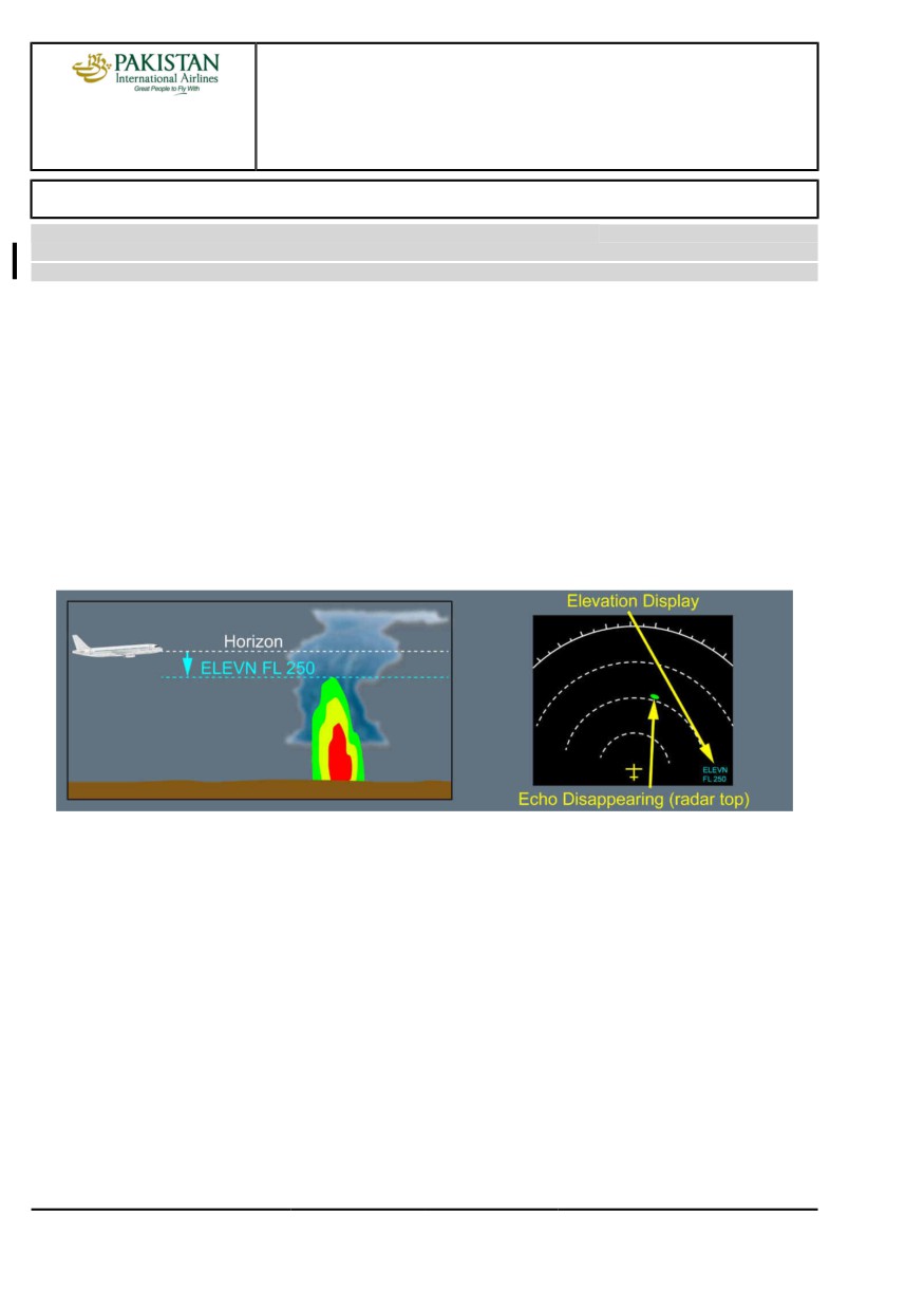
The flight crew can use the manual elevation mode (ELEVN) of the weather radar to assess
the top of a storm cell without any calculation. When the storm cell disappears from the ND, the
flight crew can read the corresponding altitude of the storm cell (or flight level, depending on the
barometric setting) on the bottom right of the ND.
Assessment of the Vertical Expansion of a Storm Cell
USE OF ON PATH AND ELEVN DISPLAY MODES
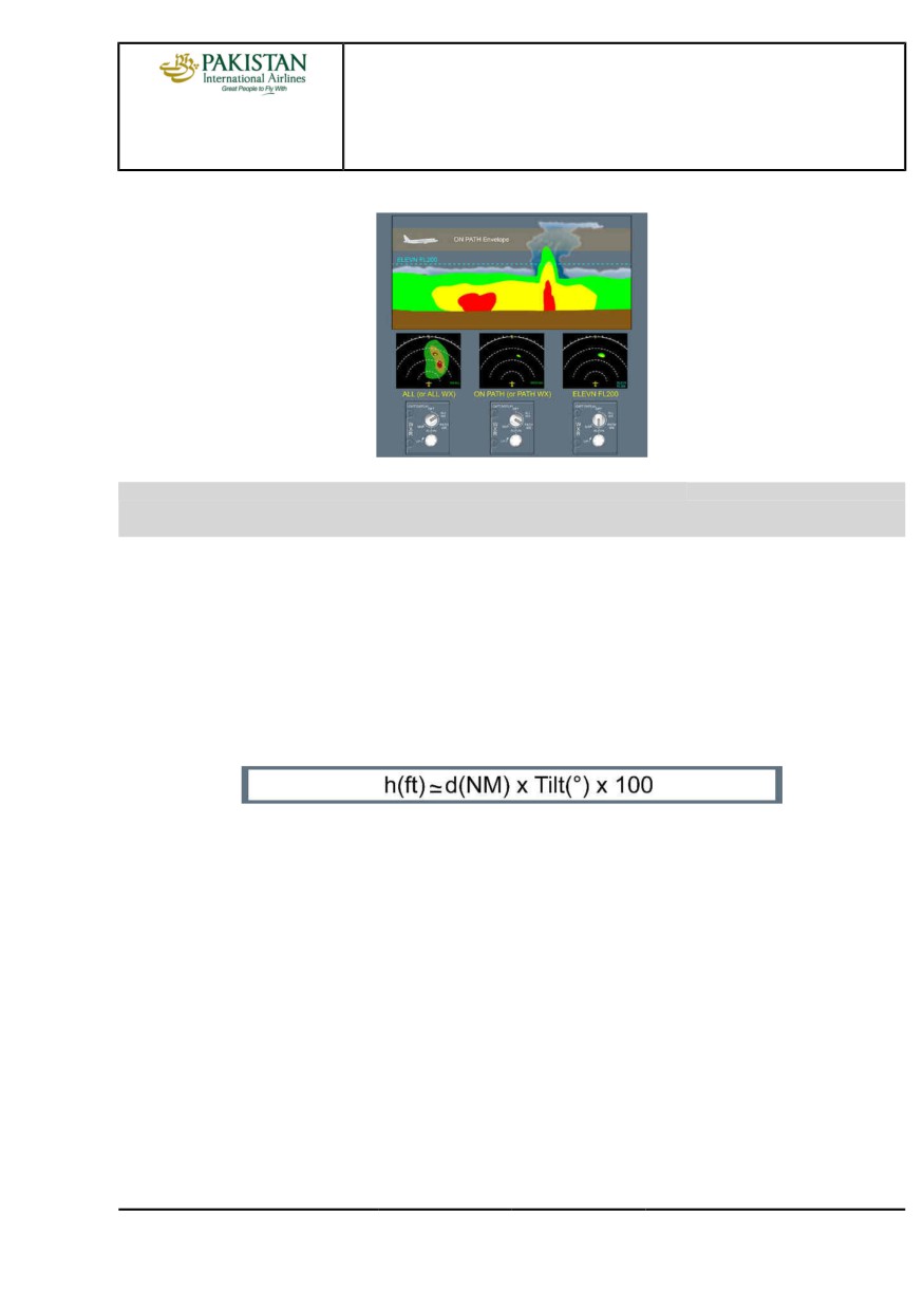
At high altitude, when the weather radar display mode is set to ON PATH (or PATH WX), any
weather return (green, yellow, or red) should be considered as a potential threat.
In the case of low altitude weather, the flight crew can also use the ELEVN display mode, with an
elevation setting above the low altitude weather, to identify the threatening storm cells.
After weather analysis, the flight crew should set the back the ALL (or ALL WX) display mode.
Refer to FCOM/DSC-34-SURV-30-15 On Path Envelope Boundaries Definition
PIA A318/A319/A320/A321 FLEET
AS-WXR P 8/20
FCTM
C →
12 JAN 22
AIRCRAFT SYSTEMS
WEATHER RADAR
A318/A319/A320/A321
FLIGHT CREW
TECHNIQUES MANUAL
Use of ON PATH and ELEVN Display Modes
Ident.: AS-WXR-A-00019767.0001001 / 20 MAR 17
Criteria: SA
Applicable to: MSN 02155-03097, 07784-07792
ASSESSMENT OF THE VERTICAL EXPANSION OF A STORM CELL
The assessment of the vertical expansion of a detected storm cell enables the flight crew to
assess the convective energy of the storm cell and therefore to identify its potential threat.
Note:
The flight crew can increase the gain in order to obtain a more visible display of the top of
the storm cell (that contains less reflective ice particles).
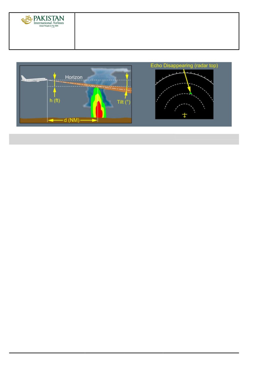
When flying towards a cell, the flight crew can estimate the vertical expansion of the cloud
above/below the aircraft altitude with the following formula:
h(ft) is the difference between the radar top altitude and the aircraft altitude.
d(NM) is the distance between the aircraft and the storm cell.
Tilt(°) is the tilt setting for which the storm cell image disappears from the ND.
Example: A weather return that disappears from the ND at 40 NM with a tilt setting of 1 ° down,
indicates that the top of the storm cell is 4 000 ft below the aircraft altitude.
PIA A318/A319/A320/A321 FLEET
AS-WXR P 9/20
FCTM
← C →
12 JAN 22
AIRCRAFT SYSTEMS
WEATHER RADAR
A318/A319/A320/A321
FLIGHT CREW
TECHNIQUES MANUAL
Assessment of the Vertical Expansion of a Storm Cell
Ident.: AS-WXR-A-00019766.0001001 / 20 MAR 17
Applicable to: ALL
INTERPRETATION OF THE COLORS OF THE WEATHER DISPLAYED ON THE ND
Particle reflectivity of a storm cell is independent of the potential weather hazard in the storm cell.
There can be a high percentage of humidity in the atmosphere, when near the sea. In this case,
thermal convection will produce clouds that are full of water. These clouds will have a high
reflectivity, but may not necessarily be a high threat.
On the other hand, in equatorial overland regions where specific converging winds produce
large-scale uplifts of dry air. As a result, these storm cells have lower reflectivity than mid-latitude
storm cells, and therefore can be difficult to detect. However turbulence in, or above these clouds
may have a higher intensity than indicated by the image on the weather radar display.
The flight crew must not underestimate a storm cell with a high vertical expansion, even if the
weather return is low.
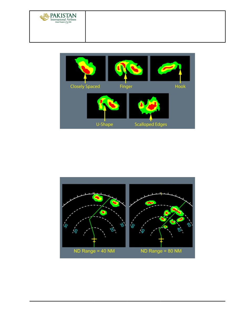
SPECIFIC WEATHER SHAPES
The flight crew should carefully observe shapes, more than colors, in order to detect adverse
weather conditions.
Areas of different colors that are near to one another usually indicate zones of severe turbulence.
Some shapes are good indicators of severe hail and signify strong vertical drafts. Shapes that
change quickly, whatever form they take, also indicate high weather activity.
PIA A318/A319/A320/A321 FLEET
AS-WXR P 10/20
FCTM
← C →
12 JAN 22
AIRCRAFT SYSTEMS
WEATHER RADAR
A318/A319/A320/A321
FLIGHT CREW
TECHNIQUES MANUAL
Specific Weather Shapes
BLIND ALLEY EFFECT
The flight crew should determine appropriate course changes to avoid adverse weather conditions,
with the use of both high and short ND ranges. This technique avoids the “blind alley effect",
defined by the following: A course change that may appear safe with a short ND range, may be
blocked when observed with a higher ND range.
Blind Alley Effect
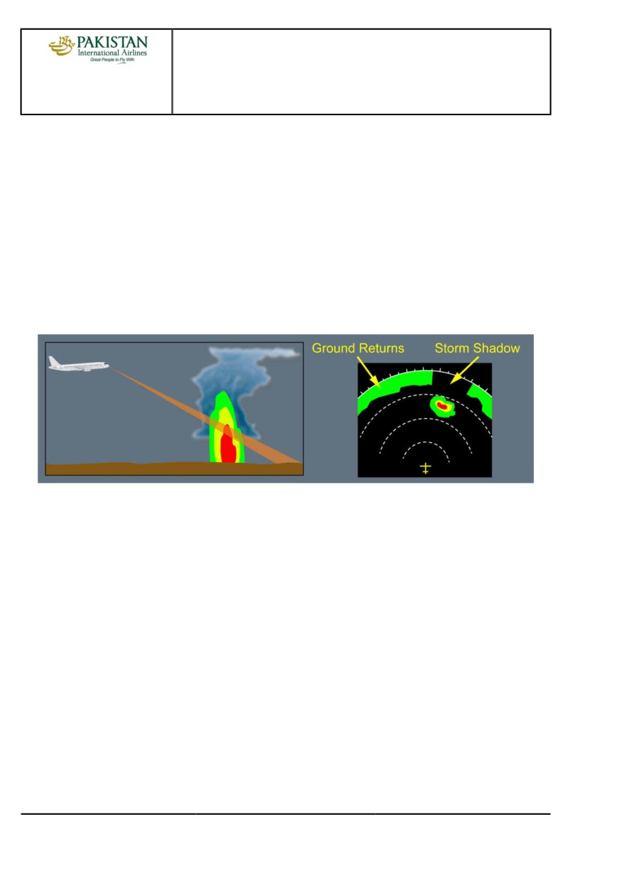
ATTENUATION EFFECT
In areas of heavy precipitation, an important part of the weather radar signal is reflected by
the frontal part of the precipitation due to its strong reflectivity. Therefore, the area behind the
precipitation returns low signals, that appears as green or black areas (storm shadows).
PIA A318/A319/A320/A321 FLEET
AS-WXR P 11/20
FCTM
← C →
12 JAN 22
AIRCRAFT SYSTEMS
WEATHER RADAR
A318/A319/A320/A321
FLIGHT CREW
TECHNIQUES MANUAL
Attenuation of long-distance weather or attenuation of ground returns can help the flight crew to
identify an area of heavy precipitation that may be a very active storm cell.
Some radars provide an indication on the ND to highlight areas that may be affected by
attenuation:
- PAC alert on Collins radars Refer to FCOM/DSC-34-SURV-30-30 Weather Radar indication
on ND
- REACT function on Honeywell radars .Refer to FCOM/DSC-34-SURV-30-30 Weather
Hazard Prediction Function Indication on ND
Note:
On a weather radar display, the flight crew should always consider a black hole behind a
red area as a potentially very active zone.
Use of Attenuation Effect to Identify an Active Storm Cell
USE OF MANUAL GAIN FOR WEATHER ANALYSIS
To assess the general weather conditions, the flight crew can use manual gain.
Manual gain adjusts the color calibration of the radar. Therefore, the weather will appear either
stronger (gain increased) or weaker (gain reduced).
When operating in heavy rain, the weather radar picture can be saturated. In this case, manually
reduce the gain will help the flight crew to identify the areas of heaviest rainfall, that are usually
associated with active storm cells.
Note:
After a storm cell analysis, the flight crew must set the GAIN knob back to AUTO/CAL.
PIA A318/A319/A320/A321 FLEET
AS-WXR P 12/20
FCTM
← C →
12 JAN 22