Robinson Helicopter Company RTR 660 (Number R00015LA). Maintenance Manual (2012) - page 3
18-41 Collective Travel
NOTE
Lengthening pitch links increases blade angles.
NOTE
When making adjustments, keep pitch links as close to neutral
(mid-travel) position as possible to preserve the adjustment
range for flight checks.
A. Collective Down
1.
Refer to Figure 18-8. Position collective stick full up and apply friction. Place
MT759-1 rigging blocks around cyclic stick in cyclic box assembly. Verify top of ball
is flush with tube within 0.030 inch. Adjust all swashplate push-pull tubes exactly
the same amount as required (one full turn = 0.48°).
2.
Position collective stick full down and apply friction.
3.
Rotate blades so pitch links are aligned with helicopter longitudinal axis.
4.
Measure and record blade angles per Section 18-40 Part B to determine the values
below. Rotate blades 180° and align per step 3 as required.
BLUE BLADE
RED BLADE
Pitch horn forward
°
Pitch horn forward
°
Pitch horn aft
+
°
Pitch horn aft
+
°
=
°
=
°
÷ 2 =
°
÷ 2 =
°
5.
Blade angles must average between 1.0° and 2.0° for collective down position.
(Final blade angle for collective down position is determined during autorotation rpm
adjustment.) Adjust main rotor blade pitch links per Section 18-13 as required (one
full barrel turn = 0.72°) until blade angles, when blades are positioned pitch horn
forward, are within 0.2°. Adjust pitch links until blade angles, when blades are
positioned pitch horn aft, are also within 0.2°.
NOTE
After making adjustments, position collective stick full up and
apply friction. Verify top of swashplate ball is flush with tube
within 0.030 inch per Figure 18-8. Adjust all swashplate push-
pull tubes exactly the same amount as required (one full turn =
0.48°). Lengthening all push-pull tubes increases blade angles.
Page 18.24
Chapter 18 Track and Balance
18-41 Collective Travel
B . Collective Up
1.
Position collective stick full up and apply friction. Place MT759-1 rigging blocks
around cyclic stick in cyclic box assembly.
2.
Rotate blades so pitch links are aligned with helicopter longitudinal axis.
3.
Measure and record blade angles per Section 18-40 Part B to determine the values
below. Rotate blades 180° and align per step 2 as required.
BLUE BLADE
RED BLADE
Pitch horn forward
°
Pitch horn forward
°
Pitch horn aft
+
°
Pitch horn aft
+
°
=
°
=
°
÷ 2 =
°
÷ 2 =
°
4.
For collective up position, blade angles must average between 12.5° and 13.5°
more than collective down position average. Adjust main rotor blade pitch links per
Section 18-13 as required (one full barrel turn = 0.72°) until blade angles, when
blades are positioned pitch horn forward, are within 0.2°. Adjust pitch links until
blade angles, when blades are positioned pitch horn aft, are also within 0.2°.
NOTE
Remeasure collective down blade angles after making adjustment
for collective up blade angles.
NOTE
After making adjustments, position collective stick full up and
apply friction. Verify top of swashplate ball is flush with tube
within 0.030 inch per Figure 18-8. Adjust all swashplate push-
pull tubes exactly the same amount as required (one full turn =
0.48°). Lengthening all push-pull tubes increases blade angles.
Chapter 18 Track and Balance
Page 18.25
18-42 Cyclic Travel
A. Cyclic Left
1. Position collective stick full down. Position cyclic stick in the longitudinal neutral
(mid travel) position, and against left stop. Apply control frictions; sandbag cyclic
stick as required.
2. Rotate blades so pitch links are aligned with helicopter lateral axis.
3. Measure and record blade angles per Section 18-40 Part B to determine the values
below. Rotate blades 180° and align per step 2 as required.
BLUE BLADE
RED BLADE
Pitch horn right
°
Pitch horn right
°
Pitch horn left
+
°
Pitch horn left
+
°
=
°
=
°
÷ 2 =
°
÷ 2 =
°
4. Blade angles must average between 7.5° and 8.5° for cyclic left position. Adjust
swashplate forward left or right push-pull tube as required (one full turn = 0.6°).
B.
Cyclic Right
1.
Position collective stick full down. Position cyclic stick in the longitudinal neutral
(mid travel) position, and against right stop. Apply control frictions; sandbag cyclic
stick as required.
2.
Rotate blades so pitch links are aligned with helicopter lateral axis.
3.
Measure and record blade angles per Section 18-40 Part B to determine the values
below. Rotate blades 180° and align per step 2 as required.
BLUE BLADE
RED BLADE
Pitch horn right
°
Pitch horn right
°
Pitch horn left
+
°
Pitch horn left
+
°
=
°
=
°
÷ 2 =
°
÷ 2 =
°
4.
Blade angles must average between 6.0° and 7.0° for cyclic right position. Adjust
swashplate forward left or right push-pull tube as required (one full turn = 0.6°).
NOTE
Remeasure cyclic left blade angles after making adjustment for
cyclic right blade angles.
Page 18.26
Chapter 18 Track and Balance
18-42 Cyclic Travel (continued)
C. Cyclic Forward
1. Position collective stick full down. Position cyclic stick in the lateral neutral (5 inches
to left of right stop) position, and against forward stop. Apply control frictions;
sandbag cyclic stick as required.
2. Rotate blades so pitch links are aligned with helicopter longitudinal axis.
3. Measure and record blade angles per Section 18-40 Part B to determine the values
below. Rotate blades 180° and align per step 2 as required.
BLUE BLADE
RED BLADE
Pitch horn forward
°
Pitch horn forward
°
Pitch horn aft
+
°
Pitch horn aft
+
°
=
°
=
°
÷ 2 =
°
÷ 2 =
°
4. Blade angles must average between 13.50° and 14.25° for cyclic forward position.
Adjust swashplate aft push-pull tube as required (one full turn = 0.44°). A coarse
adjustment can be made by adjusting swashplate forward push-pull tubes exactly
the same amount (one full turn = 0.6°).
D. Cyclic Aft
1.
Position collective stick full down. Position cyclic stick in the lateral neutral (5 inches
to left of right stop) position, and against aft stop. Apply control frictions; sandbag
cyclic stick as required.
2.
Rotate blades so pitch links are aligned with helicopter longitudinal axis.
3.
Measure and record blade angles per Section 18-40 Part B to determine the values
below. Rotate blades 180° and align per step 2 as required.
BLUE BLADE
RED BLADE
Pitch horn forward
°
Pitch horn forward
°
Pitch horn aft
+
°
Pitch horn aft
+
°
=
°
=
°
÷ 2 =
°
÷ 2 =
°
4.
Blade angles must average between 13.50° and 14.25° for cyclic aft position.
Adjust swashplate aft push-pull tube as required (one full turn = 0.44°). A coarse
adjustment can be made by adjusting swashplate forward push-pull tubes exactly
the same amount (one full turn = 0.6°).
NOTE
Remeasure cyclic forward blade angles after making adjustment
for cyclic aft blade angles.
Chapter 18 Track and Balance
Page 18.27
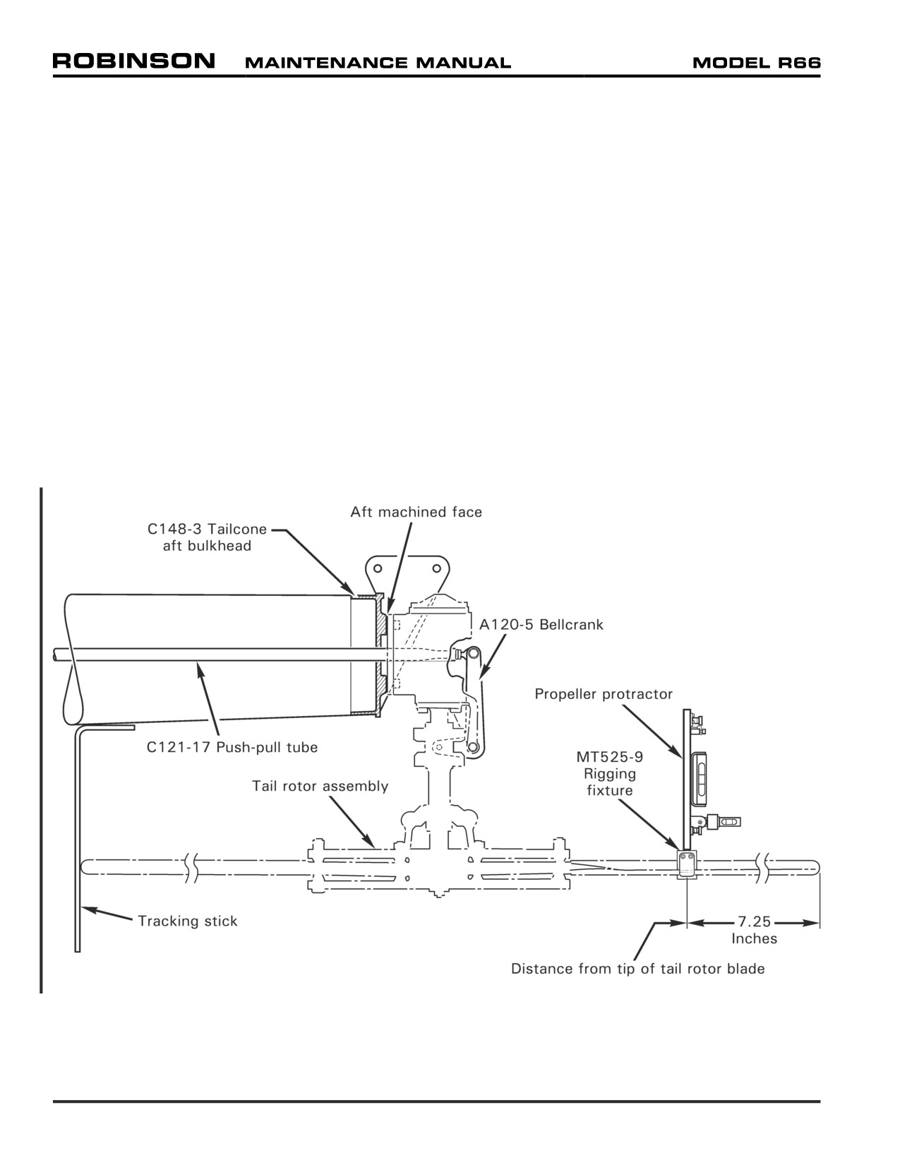
18-50 Tail Rotor Flight Control Rigging
18-51 Pedals
1. Insert a 3/16-inch diameter rigging pin through the hole in the right-hand keel panel and
the rigging pin holes in the C317-7 bellcrank.
2. Adjust the F121-9 push-pull tubes as required to obtain a dimension of 5.24 ± 0.03
in. from the lower forward NAS6604-9 bolt in C317-5 bellcrank and horizontal pedal
torque tube.
18-52 Forward Bellcrank
Remove the rigging pin and place the left pedal against its stop. Adjust the F121-11 push-
pull tube to obtain 1.08 - 1.18 inches between the bellcrank and bulkhead.
18-53 Intermediate Bellcrank
With left pedal at stop, adjust the C121-17 push-pull tube length as required to obtain 0.35
± 0.03 inch between two faces of pitch control assembly and the housing.
FIGURE 18-11 TAIL ROTOR BLADE RIGGING
Page 18.28
Chapter 18 Track and Balance
18-60 Tail Rotor Blade Rigging
1.
Level helicopter laterally, and longitudinally via main rotor hub, per Section 8-12.
2.
Place left (or right) pedal against its stop. Position tail rotor blades parallel to the
tailcone.
3.
Refer to Figure 18-11. Tape a tracking stick to tailcone at blade tip. A tracking stick can
be made using a 1” x 12” strip of aluminum with a 90º bend 2 inches from one end.
4.
Rotate tail rotor shaft weldment and mark tracking stick where each blade tip drain hole
passes. Adjust (teeter) tail rotor hub on output shaft until both blade tips pass the same
point on the tracking stick.
5.
Using felt tip marker, mark inboard surface of both tail rotor blades 7.25 inches from
each blade tip. Lay 1-inch wide strip of masking tape chordwise on each blade, centered
over marking. Mark each blade with a different color designation, such as red or blue.
6.
Have a second person hold one blade tip at the left pedal track mark with the left pedal
against its stop. Position MT525-2 rigging fixture on the aft blade, against the inboard
surface. Position propeller protractor against the fixture, measure the blade angle, and
record data below. Rotate the tail rotor 180,° and record the opposite blade angle.
Pedals Full Left
Blue Blade
°
Red Blade
+
°
=
°
÷ 2 =
° (18.5/19.0° required)
7.
Difference between blue and red blade angles may not exceed 0.4°. If blade angles
exceed this limit, remove tail rotor assembly per Section 64-10, rotate assembly one-
half revolution, and install assembly per Section 64-10. Repeat previous steps. If blade
angles still exceed relative limit, contact RHC Technical Support for replacement blade
assistance.
8.
Adjust C121-17 push-pull tube rod ends per Section 5-33 and Figures 5-1 & 5-2 as
required to obtain blade angle between 18.5° and 19.0°. One full turn of the rod end
will change the blade angle 0.33°.
9.
Have a second person hold one blade tip at the right pedal track park with the right pedal
against its stop. Position MT525-2 rigging fixture on the aft blade, against the inboard
surface. Position propeller protractor against the fixture, measure the blade angle, and
record data below. Rotate the tail rotor 180,° and record the opposite blade angle.
Pedals Full Right
Blue Blade
°
Red Blade
+
°
=
°
÷ 2 =
° (15.5/16.5° required)
10.
Adjust C121-17 push-pull tube rod ends per Section 5-33 and Figures 5-1 & 5-2 as
required to obtain blade angle between 15.5° and 16.5°. If adjusted, recheck left pedal
blade angles per previous steps.
Chapter 18 Track and Balance
Page 18.29
18-60 Tail Rotor Blade Rigging (continued)
11. If the blade angle range for left and right pedal settings cannot be obtained using the
preceding steps, the pedal travel is either too great or too small. Use the following
procedure to check and adjust pedal travel:
a. Add right and left pedal blade angles together. If the total is less than 34.0°, the pedal
total travel is too small. If the total is greater than 35.5°, the total travel is too great.
b. If the total travel is too small, first increase the right pedal travel by increasing the
length of C121-9 push-pull tube. To increase the left pedal travel, decrease the length
of C343-3 or -9 push-pull tube.
c. To decrease the total travel, shorten the C121-9 push-pull tube for right pedal travel
and increase the length of C343-3 or -9 push-pull tube for left pedal travel.
d. Recheck left and right pedal blade angles per previous steps.
12. Balance tail rotor per Section 18-20.
Page 18.30
Chapter 18 Track and Balance
CHAPTER 20
STANDARD PRACTICES
Section
Title
Page
20-10
Cleaning
20.1
20-20
Lubrication
20.2
20-30
Torque Requirements
20.3
20-31
Torque Seal
20.5
20-32
Standard Torques
20.6
20-33
Special Torques
20.7
20-34
Push-Pull Tube Rod End Adjustment
20.11
20-40
Non-Destructive Testing
20.12
20-41
Magnetic Particle Inspection
20.12
20-42
Fluorescent Penetrant Inspection
20.13
20-50
Corrosion Control
20.13
20-60
Priming and Painting
20.13
20-70
Approved Materials
20.16
20-71
Paint Strippers
20.16
20-72
Solvents and Cleaners
20.16
20-73
Fillers and Putty
20.17
20-74
Torque Seal
20.17
20-75
Primers
20.17
20-76
Powder Coat
20.18
20-77
Paints
20.19
20-78
Lubricants
20.22
20-79
Adhesives and Sealants
20.23
20-80
Storage Limits
20.24
20-90
Miscellaneous Practices
20.25
20-91
Part Interchangeability
20.25
20-92
Thermal Fitting Parts
20.26
20-93
Replacement Component Identification (Data) Plates . . .
20.26
25 OCT 2010
Chapter 20 Standard Practices
Page 20.i
Intentionally Blank
Page 20.ii
Chapter 20 Standard Practices
25 OCT 2010
CHAPTER 20
STANDARD PRACTICES
20-10 Cleaning
NOTE
Remove turbine exhaust stains from engine cowling, tailcone,
empennage, and tail rotor blades after every flight to prevent
permanent discoloration.
CAUTION
Wash helicopter exterior surfaces, windshields, and windows
with mild soap and water. Harsh abrasives, alkaline soaps, or
detergents can scratch painted or plastic surfaces, or cause
corrosion of metal. Protect areas where cleaning solution could
cause damage.
CAUTION
Never use high-pressure spray to clean helicopter. Never blow
compressed air into main or tail rotor blade tip drain holes, pitot
tube, or static ports.
WARNING
Refer to appropriate Material Safety Data Sheet (MSDS) and
take necessary safety precautions when working in proximity to
hazardous materials.
A. Cleaning Exterior Surfaces
1. Rinse away loose dirt and debris from exterior surface with clean water.
2. Apply mild soap and clean warm water solution to exterior surface using a clean,
soft cloth, sponge, or soft bristle brush. Use caution near antennas and sensitive
equipment.
3. Remove oil and grease using a cloth wetted with aliphatic naphtha.
4. Rinse all surfaces thoroughly.
5. If desired, polish painted surfaces with a good quality automotive wax using soft cleaning
cloths, or a chamois cloth, free of abrasive debris.
25 OCT 2010
Chapter 20 Standard Practices
Page 20.1
20-10 Cleaning (continued)
B.
Cleaning Windshield and Windows
CAUTION
Do not use gasoline, other alcohols, benzene, carbon tetrachloride,
thinner, acetone, or window (glass) cleaning sprays.
1. Rinse away loose dirt and debris from windshield and windows with clean water.
2. Apply mild soap and clean warm water solution, or aircraft plastic cleaner, to windshield
and windows using a clean, soft cloth or sponge in a straight back and forth motion. Do
not rub harshly.
3. Remove oil and grease using a cloth wetted with isopropyl alcohol (rubbing alcohol) or
aliphatic naphtha.
4. After cleaning plastic surfaces, apply a thin coat of hard polishing wax. Rub lightly with
a soft cloth. Do not use a circular motion.
5. To remove scratches, rub windshield or windows with jeweler’s rouge then hand polish
with commercial plastic polish. Polish in figure eight motion.
C. Cleaning Seat Assemblies and Back Rests
1. Vacuum and brush, then wipe with damp cloth. Dry immediately.
2. Soiled upholstery, except leather, may be cleaned with a good upholstery cleaner suitable
for the material. Follow manufacturer’s instructions. Avoid soaking or harsh rubbing.
3. Leather should be cleaned with saddle soap or a mild hard soap and water.
D. Cleaning Carpet
Remove loose dirt with a whisk broom or vacuum. For soiled spots and stains, use
nonflammable dry cleaning liquid.
20-20 Lubrication
WARNING
Refer to appropriate Material Safety Data Sheet (MSDS) and
take necessary safety precautions when working in proximity to
hazardous materials.
All R66 bearings are sealed or self-lubricating and do not require periodic lubrication.
The engine oil tank, the main and tail rotor gearboxes, and the hydraulic reservoir require
servicing when indicated by sight gage level. Additionally, change engine, gearbox, or hydraulic
oil and clean respective sight gage when oil becomes so dirty its level cannot be determined.
Change hydraulic oil when notedly odorous.
When installing a new or overhauled main rotor gearbox, replace filter at first 100-hour
inspection after installation. Thereafter, replace filter at scheduled intervals per Section 5-20.
When installing a new or overhauled tail rotor gearbox, drain and flush after first 4 hours
of flight or first chip light, whichever occurs first. Thereafter, drain and flush gearbox at
scheduled intervals per Section 5-20.
Servicing procedures are located in Chapter 12.
Page 20.2
Chapter 20 Standard Practices
25 OCT 2010
20-30 Torque Requirements
A. Tool Calibration
Dimensions and tolerances given in this manual are critical. Calibrate measuring tools per
manufacturers recommendation at least once a year, when tool is dropped, misused, or
calibration is suspect. This includes torque wrenches, micrometers, calipers, dial indicators,
and spring scales.
WARNING
Proper torque is critical. Always use calibrated wrenches and
undamaged, properly lubricated
(where applicable) hardware.
Ensure clamping surfaces are clean, and clamp only bare metal
or wet-primed surfaces. Improper torque or dirty or painted
clamping surfaces may result in loss of clamp-up, hardware or
part damage, and premature failure.
B. Torque Value
Torque fasteners to standard dry values listed in Section 20-32 unless otherwise specified.
If torque is applied by rotating bolt, increase torque value by 10% to account for higher
friction at bolthead and shank.
For example, the torque wrench setting for an NAS1305 bolt used with a NAS1068 nutplate
is determined as follows:
NAS1305 bolt (5 indicates 5/16 inch size) dry torque per Section 20-32
240 in.-lb
Add 10% because torque must be applied at bolt head
+ 24 in.-lb
Torque wrench setting
264 in.-lb
C. Secondary Locking Mechanism
A secondary locking mechanism is required on all critical fasteners. B330 stamped nuts
(palnuts) serve as secondary locking mechanisms in most areas on the helicopter, and are
torqued per Section 20-32. The R66 Illustrated Parts Catalog (IPC) lists secondary locking
mechanisms for specific fasteners.
D. Critical Fastener
A critical fastener is one which, if removed or lost, would jeopardize safe operation of the
helicopter. This includes joints in the primary control system, and non-fail-safe structural
joints in the airframe, landing gear, and drive system.
WARNING
Assembly of flight controls is critical and requires inspection
by a qualified person. If a second person is not available,
RHC recommends the installer take a 5-minute break prior to
inspecting flight control connections he has assembled.
25 OCT 2010
Chapter 20 Standard Practices
Page 20.3
Given
Symbols
Y
= Unknown
Y
= Torque wrench setting
T
= 135 in.-lb
T
= Torque applied to fastener
L
= 10 in.
L
= Length of torque wrench
A
= 1.5 in.
A
= Length of adapter
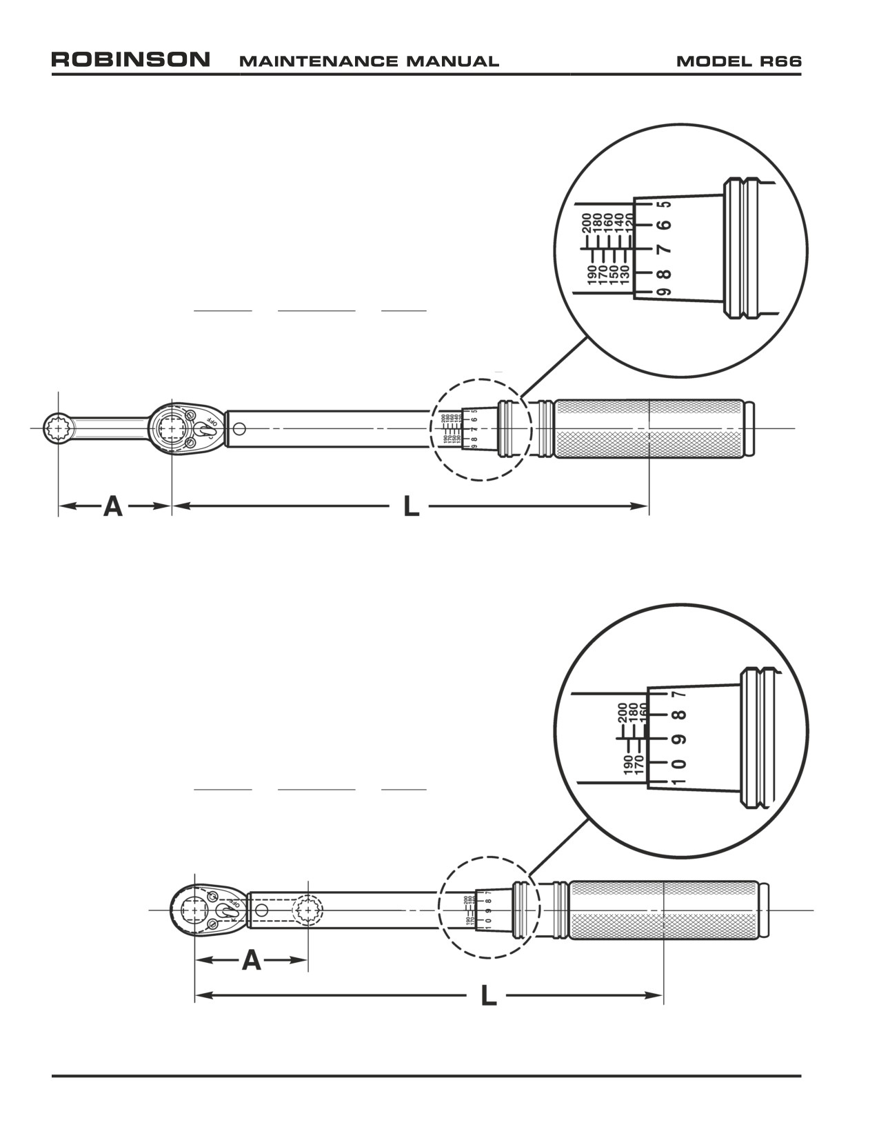
When using an adapter that lengthens torque wrench effective length,
calculate torque wrench setting using the formula below:
EXAMPLE
T x L
135 x 10
1350
Solve for Y =
=
=
= 117.39
L + A
10 + 1.5
11.5
Set torque wrench to 117 in.-lb to torque fastener to 135 in.-lb.
FIGURE 20-1 LENGTHENING TORQUE WRENCH EFFECTIVE LENGTH
Given
Symbols
Y
= Unknown
Y
= Torque wrench setting
T
= 135 in.-lb
T
= Torque applied to fastener
L
= 10 in.
L
= Length of torque wrench
A
= 1.5 in.
A
= Length of adapter
When using an adapter that shortens the torque wrench effective length,
calculate torque wrench setting using the formula below:
EXAMPLE
T x L
135 x 10
1350
Solve for Y =
=
=
= 158.82
L - A
10 - 1.5
8.5
Set torque wrench to 159 in.-lb to torque fastener to 135 in.-lb.
FIGURE 20-2 SHORTENING TORQUE WRENCH EFFECTIVE LENGTH
Page 20.4
Chapter 20 Standard Practices
25 OCT 2010
20-30 Torque Requirements (continued)
WARNING
Two threads minimum must be exposed beyond nut on any
installation to insure proper locking of fastener. Four threads
maximum may be exposed. More than four threads exposed
may allow nut to seat against bolt shank, resulting in insufficient
joint clamping.
CAUTION
Never substitute AN bolts for NAS bolts. NAS bolts have higher
tensile strength.
E.
Torque Requirements
1. Bolt and nut are to be clean and dry except when assembly procedure specifies anti-
seize or thread-locking compound.
2. If chattering or jerking occurs, disassemble and re-torque fastener.
3. If special adapters which change effective length of torque wrench are used, final torque
value must be calculated using formulas in Figures 20-1 and 20-2.
4. Proper thread engagement requires 2-4 threads beyond primary self-locking nut (palnuts
excepted).
5. Torque wrenches must be calibrated annually, when dropped, or when a calibration
error is suspected.
Any self-locking nut whose drag has deteriorated appreciably must be replaced. Damaged
hardware must be replaced.
20-31 Torque Seal
WARNING
Refer to appropriate Material Safety Data Sheet (MSDS) and
take necessary safety precautions when working in proximity to
hazardous materials.
Refer to Figure 5-1. Torque seal (paint) is applied to all critical fasteners after palnut
installation in a stripe extending from the fastener's exposed threads across both nuts
and onto the component. Subsequent rotation of the nut or bolt can be detected visually.
Position torque stripes for maximum visibility during preflight inspections. Approved torque
seal is listed in Section 20-74.
Chapter 20 Standard Practices
Page 20.5
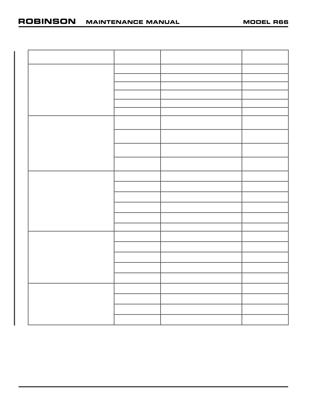
20-32 Standard Torques
EXAMPLE
DRY TORQUE
FASTENER SERIES
SIZE
FASTENER
(IN.-LB)
10-32
NAS6603
50
NAS 1300 Bolts
1/4-28
NAS6604
120
NAS 6600 Bolts
5/16-24
NAS6605
240
NAS 600 THRU 606 Screws
NAS 623 Screws
3/8-24
NAS6606
350
NAS 1351 Screws
NAS 1352 Screws
7/16-20
NAS6607
665
1/2-20
NAS6608
995
AN3 Bolts
10-32
AN3
37
AN4 Bolts
AN6 Bolts
AN8 Bolts
1/4-28
AN4
90
AN502 Screws
AN503 Screws
AN509 Screws
3/8-24
AN6
280
AN525 Screws
MS24694 Screws
1/2-20
AN8
795
MS27039 Screws
10-32
B330-7 (MS27151-7)
6 to 15
1/4-28
B330-13 (MS27151-13)
11 to 25
5/16-24
B330-16 (MS27151-16)
20 to 40
STAMPED NUTS
(PALNUTS)
3/8-24
B330-19 (MS27151-19)
29 to 60
7/16-20
B330-21 (MS27151-21)
42 to 85
1/2-20
B330-24 (MS27151-24)
54 to 110
1/8-27
N/A
60
1/4-18
N/A
85
TAPERED PIPE
3/8-18
N/A
110
THREADS
1/2-14
N/A
160
3/4-14
N/A
230
10-32
AN315-3
15
1/4-28
AN316-4
40
ROD END JAM NUTS
(AN315 and AN316)
5/16-24
AN316-5
80
3/8-24
AN316-6
110
1.
Values include nut self-locking torque.
2.
Increase values 10% if torqued at bolt head.
3.
For elbow & tee fittings which require alignment, torque to indicated value then tighten to desired position.
4.
Values ± 10% unless range is specified.
5.
Unless otherwise noted, thread sizes 8-32 & smaller are not used for primary structure & do not require specific
torque.
Page 20.6
Chapter 20 Standard Practices
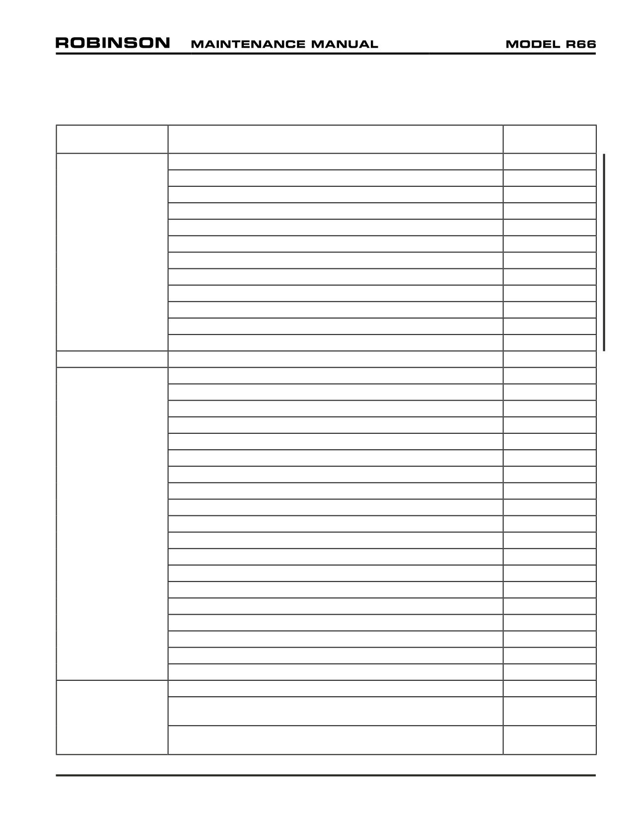
20-33 Special Torques
Special torques supersede standard torques listed in Section 20-32.
TORQUE
AREA*
FASTENER*
(IN.-LB)*
(1) D795-8 line assembly, B-nuts
150
(1) D799-2 switch assembly
90
(1) D799-3 switch assembly
90
(1) G783-1 condenser, dessicant cap
100
(1) G784-1 evaporator assembly, inlet B-nut to 134-32 TXV
210
AIR CONDITIONING
(1) G794-1 hose assembly, B-nuts
210
(OPTIONAL
(1) G794-2 hose assembly, B-nuts
210
EQUIPMENT)
(1) G794-3 hose assembly, B-nuts
150
(1) G810-1 line assembly, B-nuts
210
(1) G811-1 line assembly, B-nuts
210
(2) AN924-8D nuts
360
(2) 91292A135 screws
70
CABIN
(1) MS21042L5 nut, ground handling ball
240
(1) B289-2 bolt, drain
70
(1) B563-2 sight gage
150
(1) D205-19 hose assembly, B-nuts
270-300
(1) D205-20 hose assembly, B-nuts
270-300
(1) F723-1 line assembly, B-nuts
330-360
(1) F723-2 line assembly, B-nuts
230-260
(1) F723-3 line assembly, B-nuts
230-260
(1) F723-4 line assembly, B-nuts
230-260
COOLING SYSTEM
(1) F724-1 line assembly, B-nuts
110-130
(ENGINE AND MAIN
(1) F724-2 line assembly, B-nuts
110-130
ROTOR GEARBOX
OILS)
(1) F724-3 line assembly, B-nuts
110-130
(2) AN815-8D unions, on F649-1 oil cooler
230-260
(2) AN832-8D unions, at firewall
230-260
(1) AN832-10D union, at firewall
330-360
(2) AN924-8D nuts, at firewall
230-260
(1) AN924-10D nut, at firewall
330-360
(2) AN926-6D nuts, securing F823-1 thermostat assembly to firewall
110-130
(2) AS5169D04L fitting, on F649-1 oil cooler
50-65
(1) MS28034-1 oil temperature sender, to tank
120
(16) MS51861-37C screws, securing door hinge assemblies
36
(2) 94830A030 nuts, securing G904-1 gas spring ball studs at
DOOR HINGES AND
100
baggage compartment door
GAS SPRINGS
(2) 94830A030 nuts, securing G394-1 gas spring ball studs at aft
100
doors
Chapter 20 Standard Practices
Page 20.7
20-33 Special Torques (continued)
TORQUE
AREA*
FASTENER*
(IN.-LB)*
(2) C394-2 ball stud, at forward doors, to frame
150 wet
DOOR HINGES AND
(2) D575-2 and (2) D575-3 ball joints, at forward doors' D573-4
GAS SPRINGS
37
rods
(2) F650-1 bolt, forward main rotor gearbox and G201 frame
90 FT-LB
mounts
Bolt head or nut
DRIVE SYSTEM
(2) F650-2 bolt, aft main rotor gearbox and G201 frame mounts
90 FT-LB
Bolt head or nut
(4) MS20074-04-06 bolts, at tail rotor gearbox C112-1 output cap
60
(8) NAS6604-6 bolts, securing vertical stabilizers to upper horizontal
150
stabilizer
EMPENNAGE
(1) NAS1352-3-14P screw, securing guard assembly blocks to
40
lower vertical stabilizer
(1) Fuel control unit (FCU) lever nut
40-50
ENGINE CONTROLS
(1) Power turbine governor (PTG) lever nut
40-50
(1) AN316-7R nut, compressor service line
150
ENGINE INDUCTION
(1) AN929-4 cap, compressor service line
60
(5) B289-1 bolts, fuel sender
37
(1) B330-6 palnut, fuel sender center stud
11
(1) G254-2 fitting, vent assembly
200
(1) G254-6 retainer, vent assembly
200
FUEL SYSTEM
(1) MS21042L3 nut, securing fuel valve control wire
27
(1) B254-3 strainer, fuel bladder outlet
150
(1) D205-21 hose assembly, fuel bladder outlet to fuel valve, B-nuts
110-130
(1) AN924-5D nut, low fuel warning switch assembly
150
(1) B283-12 hose assembly, fuel valve to fuel pump inlet, B-nuts
110-130
(1) G391-1 line assembly B-nuts
230-260
(1) G391-2 line assembly B-nuts
100
(1) G391-3 line assembly B-nuts
100
HEATER
(1) G391-4 line assembly B-nuts
100
(1) G391-5 line assembly B-nuts
230-260
(1) MS21042L3 nut, securing control wire
25-30
(1) AN820-4 cap, on reservoir AN804D4 T-fitting
60
(1) AN820-6 cap, on reservoir AN834-6D T-fitting
120
(2) AN818-4D nuts, F902-1 line assembly and right hand servo
135-150
HYDRAULIC HOSES
(2) AN818-6D nuts, F902-2 line assembly and right hand servo
110-130
& FITTINGS
(2) D452-3 nuts, on aft and left hand servos
60
(3) D452-4 nuts, on aft and left hand servos and on reservoir
90
(1) D452-6 nut, on reservoir
150
(2) B330-19 palnut, on aft and left hand servos
30
Page 20.8
Chapter 20 Standard Practices
20-33 Special Torques (continued)
TORQUE
AREA*
FASTENER*
(IN.-LB)*
(3) B330-21 palnut, on aft and left servos and on reservoir
45
(1) B330-25 palnut, on reservoir
75
(1) D205-14 line assembly B-nuts
95-105
HYDRAULIC HOSES
(1) D205-17 line assembly B-nuts
95-105
& FITTINGS
(1) D205-18 line assembly B-nuts
135-150
(1) D205-22 line assembly B-nuts
95-105
(1) D205-23 line assembly B-nuts
135-150
(1) D205-24 line assembly B-nuts
135-150
(1) D487-3, filler-vent
100
HYDRAULIC
(1) D516-1, filter cap
150
RESERVOIR
(1) B563-3, sight gage
150
HYDRAULIC
(1) MS21042L08 nut, attaching D200-2 scissors
25
SERVOS
(1) B330-6 palnut on D200-2 scissor apex fastener
5-10
(4) NAS6604-46 bolts, securing ground handling wheel
70
support weldments to skid tubes
(2) NAS6607P44 bolt, securing shackles to fuselage
66 FT-LB
LANDING GEAR
(4) NAS607P20 bolt, securing landing gear to fuselage
66 FT-LB
supports and shackles
(4) B277-28 clamp, securing fairings to struts
15
(1) D674-2 hose assembly, B-nuts
230-260
(1) D674-6 hose assembly, B-nuts
230-260
(1) D674-7 hose assembly, B-nuts
110-130
POP-OUT FLOATS
(OPTIONAL
(1) D674-9 hose assembly, B-nuts
230-260
EQUIPMENT)
(1) D674-11 hose assembly, B-nuts
230-260
(1) D674-12 hose assembly, B-nuts
230-260
(1) D674-13 hose assembly, B-nuts
230-260
MAIN ROTOR
(2) B289-2 bolts, per blade, self-sealing
60-80
BLADE
(2) C722-3 screws, per blade, tip balance weight
55
MAIN ROTOR
(2) MS21042L04 nut, low rotor horn V3-1 switch
4-5
FLIGHT CONTROLS
(1) MS21245L8 nut, securing engine shaft input yoke to
50 FT-LB
main rotor gearbox
(1) F904-1 pinion plug, securing rotor shaft input yoke to
30 FT-LB Wet
main rotor gearbox
Apply A257-9 to threads
(1) AN814-8D plug, main rotor gearbox filler plug
150
MAIN ROTOR
GEARBOX
(1) B254-3 strainer, main rotor gearbox sump
200
(1) D205-25 hose, sump to pump B-nuts
120
(1) B566-1 chip detector, main rotor gearbox
150
(1) chip detector wire terminal nut
4-6
(1) B563-2 sight gage
150
Chapter 20 Standard Practices
Page 20.9
20-33 Special Torques (continued)
TORQUE
AREA*
FASTENER*
(IN.-LB)*
New bolt: 0.021-0.022
inch elongation, wet
(1) NAS634-105 bolt, teeter hinge and
MAIN ROTOR HUB
Used bolt: 0.020-0.022
(2) NAS634-105 bolt, coning hinges
inch elongation, wet, and
cotter pin holes must align
MAST TUBE
(1) B277-064 clamp, lower rib to mast tube
50
PITCH LINKS
(2) 21FKF-813 self-locking jam nuts, main rotor pitch links
300
(1) D745-3 (pressure) switch assembly
65
(1) F147-1 screw, FCU minimum throttle stop
20
(1) F170-1 fitting, engine gearbox
100
(1) F727-1 line assembly, fuel pump drain
50-65
(1) F727-2 line assembly, horizontal turbine-firewall shield
50-65
assembly drain
(1) F741-1 line assembly, fuel differential pressure switch
75-85
(1) G426-1 (fuel differential pressure) switch assembly
100
(2) nuts, securing harness wire to MGT thermocouple
20
studs, engine-supplied
(2) nuts, securing harness wires to starter-generator small
20
terminals, starter-generator supplied
(2) nuts, securing harness wires to starter-generator large
180
terminals, starter-generator supplied
(1) nut, securing harness wire to ignition exciter box, engine-
POWERPLANT
15
supplied
(2) nuts, securing harness and (2) MS21919WCH4 clamps
40
to engine accesory gearbox, engine-supplied
(4) nuts, securing F577-1 bracket assembly, engine-supplied
40
(6) nuts, securing rear PTO cover to engine, engine-supplied
80
(2) tee bolts, securing F173-1 struts to engine, engine-
35-40
supplied
(2) AN815-8D unions, engine oil outlet and oil tank vent
250
(1) AN815-10D union, engine oil inlet
375
(1) AN919-0D reducer and (1) AN919-2D reducer
100
(6) NAS6605H3 bolts, securing (2) F593-1 support
110
assemblies to engine
(2) NAS6605H4 bolts and (1) NAS6605H2 bolt, securing
110
F593-3 plate to engine
(1) CV26-77 check valve, engine oil outlet (early R66s)
250
POWERPLANT
(3) MS21042L3 nuts, securing control wires
25-30
CONTROLS
(26) NAS1352N08-8 screws, securing spacers, sleeve
35 wet
SWASHPLATE
assembly, shield, and retainers
(2) NAS1352N08-4 screws, securing B769-2 bracket
35
Page 20.10
Chapter 20 Standard Practices
20-33 Special Torques (continued)
TORQUE
AREA*
FASTENER*
(IN.-LB)*
(1) MS21042L4 nut, securing C119-2 bumper
120
TAIL ROTOR
(1) NAS6606-53 bolt, teeter hinge
380
TAIL ROTOR
(1) MS21042L4 nut, outboard of F316-1 bellcrank assembly
90
FLIGHT CONTROLS
(1) A610-1 vent assembly
100
(1) B563-1 sight gage
150
(1) B566-2 chip detector
100
(1) AN320-8 nut, input yoke
35-45 FT-LB
TAIL ROTOR
(4) MS20074-04-06 bolts, input cap
60
GEARBOX
(8) MS20074-04-06 bolts, input housing and output cap
100
(1) MS21042L5 nut, pitch control housing
240
(4) NAS1352-5-12P bolts (undrilled), gearbox-to-tailcone
240
attachment
TAIL ROTOR
(1) NAS1352-3-14P screw, securing block assembly to
40
GUARD
stabilizer
WINDOWS
(22) AN526C832R12 screw, thru center brace
16
1. Values include nut self-locking torque.
2. Increase values 10% if torqued at bolt head.
3. For elbow & tee fittings which require alignment, torque to indicated value then tighten to desired position.
4. Values ± 10% unless range is specified.
5. Unless otherwise noted, thread sizes 8-32 & smaller are not used for primary structure & do not require
specific torque.
20-34 Push-Pull Tube Rod End Adjustment
NOTE
Refer to Section 18-13 to adjust C258-1 main rotor pitch links.
The following procedure is standard for adjusting push-pull tube rod ends:
1. Loosen palnut and jam nut on rod end shank.
2. Remove hardware securing push-pull tube rod end to attachment point per respective
instructions.
3. Screw rod end in or out of push-pull tube as required to obtain proper rigging
adjustment.
4. After any rod end adjustment, verify rod end threaded shank blocks passage of 0.020-
inch diameter wire thru the witness hole in the push-pull tube per Figure 5-1. When no
witness hole is provided, refer to Figure 5-1 for maximum rod end extension.
5. Install fastener securing push-pull tube to attachment point per respective instructions.
6. Refer to Figure 5-2. Position rod ends to allow as much push-pull tube rotation as
possible without binding. Standard torque jam nuts & palnuts per Section 20-32 &
torque stripe per Figure 5-1.
Chapter 20 Standard Practices
Page 20.11
20-40 Non-Destructive Testing
WARNING
Refer to appropriate Material Safety Data Sheet (MSDS) and
take necessary safety precautions when working in proximity to
hazardous materials.
20-41 Magnetic Particle Inspection
Ferromagnetic steel parts must be inspected for structural defects using magnetic particle
inspection.
Steel parts covered by this specification shall be inspected per ASTM E 1444 wet process
with ultra-violet light. Applicable requirements and limitations of the above standard shall
apply. Parts shall be thoroughly demagnetized and cleaned after inspections. Record the
size and location of all rejectable indications.
Procedures and equipment used to perform the inspection shall conform to requirements
of ASTM E 1444. Whenever possible, parts shall be inspected with both circular and
longitudinal magnetization.
A. Inspection Criteria
Parts
(except gears) which are inspected by magnetic particle inspection shall be
accepted or rejected according to the following criteria:
Acceptable indications:
yy Indications smaller than 0.015 inch are not considered ratable.
yy Indications caused by sharp changes in cross-section or part geometry.
Rejectable indications:
yy Indications interpreted as cracks, seams, laps, shuts, or any flaws which are open
to the surface.
yy Indications oriented at an angle of more than 15 degrees from the longitudinal axis
with length exceeding 0.125 inch.
yy Circumferential indications on any shoulder or fillet (changes in diameter).
yy Any indications which break over an edge, shoulder, fillet radius, keyway, spline, or
an adjacent area of part more than 0.015 inch.
yy Indications caused by undercuts at the toe of a weld.
yy Indications caused by cracks in the weld or parent metal.
yy Indications caused by inclusions in weld material exceeding 0.1 inch in length.
Page 20.12
Chapter 20 Standard Practices
20-42 Fluorescent Penetrant Inspection
This specification provides for surface inspection of parts fabricated from nonmagnetic
materials to detect discontinuities open to the surface, such as cracks, cold shuts, laps,
porosity and other surface defects.
Applicable requirements and limitations of ASTM E 1417 shall apply. After inspection is
complete, solvent clean parts.
The step-by-step procedure and equipment used to perform the inspection shall be
accomplished per ASTM E 1417.
A. Inspection Criteria
Parts inspected by fluorescent penetrant method shall be accepted or rejected on basis
of acceptance limits specified. If acceptance limits are not specified, rejectable surface
defects and any of the following:
yy Cracks
yy Seams
yy Cold shuts or laps
yy Surface inclusions
yy In castings, aligned discontinuous surface indications other than cracks, cold shuts
and inclusions are rejectable if more than 3/8 inch in length.
20-50 Corrosion Control
[Reserved].
20-60 Priming and Painting
WARNING
Refer to appropriate Material Safety Data Sheet (MSDS) and
take necessary safety precautions when working in proximity to
hazardous materials.
A. Priming
This specification outlines preparation and application requirements for primers. Primers
provide corrosion protection and a final finish or a base for the final finish.
25 OCT 2010
Chapter 20 Standard Practices
Page 20.13
20-60 Priming and Painting (continued)
A. Priming (continued)
Use only approved materials listed in Section 20-70. Parts shall be prepared in the following
manner:
1.
Preparing Aluminum
Unless otherwise specified, chemical conversion coating using Alodine 1201 is the
standard treatment before priming aluminum. Follow manufacturers instructions for
application of Alodine. However, if bare or clad aluminum is primed without conversion
coating, the following procedure must be used:
a. Alkaline clean if immersion is practical, otherwise wipe clean with QSOL 220 or
equivalent degreasing agent.
b. Lightly scuff the surface with Scotch Brite pads.
c. Wipe with a tack rag to remove any foreign material or damp wipe with QSOL 220
or equivalent solvent.
d. Air dry. Do not touch parts with bare hands until primed.
2.
Preparing Steel
Alkaline clean is the preferred method for cleaning steel except where immersion is not
practical. For extremely greasy or dirty steel parts a preclean in a solvent vapor bath
using Perchloroethylene, or hand wipe with QSOL 220 and air dry may be used on a
limited basis.
If a solvent vapor bath is selected, a degreaser which incorporates a spray flushing
nozzle must be utilized except for specific parts noted herein. Clean steel parts by:
a. Immerse parts in a solvent vapor bath for 3-5 minutes to loosen all dirt, oil and
grease.
b. After vapor bath, spray all holes, cavities, and recesses with clean liquid solvent
from a pressurized nozzle to thoroughly flush and remove any debris.
c. Air dry thoroughly using filtered, dry, compressed air.
d. Wrap parts in clean paper or hang from racks to retain cleanliness until ready for
priming. Do not touch parts with bare hands until primed.
3.
Application
Apply primer after mixing per manufacturer’s recommendations. Total primer coating
is not to exceed 0.005 inch thickness. For parts with internal openings, such as tubes,
prime the inside as follows:
a. Thin primer to watery consistency using required reducer.
b. Pour in primer, slosh around, then drain immediately.
c. Dry parts at least (6) hours before using.
4.
Inspection
Inspect for complete coverage and excessive thickness. If primer is excessively thick,
strip part using plastic media blast and re-prime.
Page 20.14
Chapter 20 Standard Practices
25 OCT 2010
20-60 Priming and Painting (continued)
B. Painting
This specification provides final paint finish requirements.
Do not prime or paint with a top coat finish the following areas (unless directed):
yy Sliding friction joints.
yy Stainless steel parts.
yy Swivel joints and adjustable rod ends.
yy Plastic, rubber, electrical components and wires or similar materials.
yy Bolted joints where torque is a specific requirement for clamping action.
yy Bearing press fit or close tolerance slip fit joints (except where wet chromate primer is
part of the assembly procedure).
1. Prior to paint application, clean and prime surface per Part A.
2. Painting Sequence - In general, most parts will be cleaned and primed as detail parts,
however, in some cases, such as the gearbox assembly, this will not be practical and
priming and painting may be done as an assembly.
25 OCT 2010
Chapter 20 Standard Practices
Page 20.15
20-70 Approved Materials
The following items are available from the noted manufacturer(s) or their distributor(s). Check
with appropriate regulatory authority(s) for allowable usage of materials.
WARNING
Refer to appropriate Material Safety Data Sheet (MSDS) and
take necessary safety precautions when working in proximity to
hazardous materials.
CAUTION
Follow product manufacturer’s instructions for handling and
storage.
20-71 Paint Strippers
PRODUCT
MANUFACTURER/SUPPLIER
APPLICATION
Cee-Bee Stripper
McGean-Rohco: Cee-Bee Division
Metal parts, except blades and flex plates.
A-292
Downey, CA
Plastic Media
Pauli & Griffin Co.
Metal parts except blades and unsupported
Blasting System
Vacaville, CA
sheet metal less than 0.040 inch thick.
20-72 Solvents and Cleaners
Product
Manufacturer/Supplier
Application
QSOL 220
Safety-Kleen Systems, Inc.
General use for cleaning prior to applying
Plano, TX
primer, topcoat, adhesive, or sealant.
Benzene, 1-Chloro-4
Any
“ “
(Trifluoromethyl)
PCBTF
Final Klean 3909S
Du Pont Chemical
“ “
Los Angeles, CA
EM-Citro*
LPS Laboratories, Inc.
“ “
Tucker, GA
Acetone
Any
“ “
Lacolene
Any
Acrylic plastic cleaner only.
(Aliphatic
Hydrocarbon)
Presolve
LPS Laboratories, Inc.
Hydraulic components only.
Tucker, GA
Tetrachloroethylene
Any
Vapor degreaser.
(Perchloroethylene)
Page 20.16
Chapter 20 Standard Practices
25 OCT 2010
20-72 Solvents and Cleaners (continued)
Product
Manufacturer/Supplier
Application
815 GD
Brulin Corporation
Ultrasonic cleaning, general use.**
Indianapolis, IN
SF50
L&R Mfg. Co.
“ “
Kearny, NJ
#112 Ammoniated or
L&R Mfg. Co.
Ultrasonic cleaning, avionics components
#222 Nonammoniated
Kearny, NJ
only.
cleaning & rinse solution
*May be used on acrylic plastic.
**Mix 5%-20% by volume; titration not required.
20-73 Fillers and Putty
Product
Manufacturer/Supplier
Application
315 Putty & Blue Cream
DuPont
Minor surface imperfections.
Hardener
Los Angeles, CA
051144-05960 Acryl -
3M Co.
“ “
Green Spot Putty
St. Paul, MN
SBF1191
Gearhead Products
“ “
Indianapolis, IN
20-74 Torque Seal
PRODUCT
MANUFACTURER/SUPPLIER
APPLICATION
F-900
Organic Products Co.
Torque seal.
(Any color except red)
Irving, TX
20-75 Primers
PRODUCT
MANUFACTURER/SUPPLIER
APPLICATION
Gray epoxy CA 7501
Desoto Aerospace Coatings,
Unlimited.
with CA 7501B activator
PRC - Desoto Int., Inc.
Glendale, CA
Gray epoxy 44-GY-79
Deft, Inc.
Aluminum parts and assemblies, and
with 44-GY-79 activator
Irvine, CA
fiberglass parts.
Aviation Primer, Green,
Valspar Corporation
Limited or touch-up use only.
A902 (Aerosol)*
Medina, OH
*Shelf life two years
25 OCT 2010
Chapter 20 Standard Practices
Page 20.17
20-76 Powder Coat
Epoxy and topcoat powders are electrostatically applied to steel parts and baked for 10-15
minutes after each powder application. Curing temperature must not exceed 400° F.
Zinc rich epoxy powder coating thickness allowance is 0.001 to 0.004 inches.
PRODUCT
MANUFACTURER
13-7004 Corvel Grey
Dow Chemical Co.
Zinc-Rich Epoxy Powder*
81-2158 Vitralon Grey
Pratt & Lambert Chemical Coatings
Zinc-Rich Epoxy Powder*
Buffalo, NY
Total coating thickness allowance is 0.003 to 0.007 inches (epoxy and topcoat). Coating
may exceed maximum thickness in local areas due to part geometry.
PRODUCT
MANUFACTURER
39/80020 Smooth Matte
Tiger Drylac USA
Black
Cucamonga, CA
Polyester Topcoat Powder*
49/72460 Smooth Glossy
“ “
Gray RAL 7043
Polyester Topcoat Powder*
49/22460 Smooth Glossy
“ “
Yellow RAL 1028
Polyester Topcoat Powder*
PFWF104S9 White
Dupont Co.
Wilmington, DE
*Shelf life: 12 months from date of manufacture at ambient temperature.
Page 20.18
Chapter 20 Standard Practices
25 OCT 2010
20-77 Paints
Refer to Figures 20-3 and 20-4 for finish code locations. Paint codes for specific helicopter
serial numbers are listed in the front of factory-supplied R66 Airframe Maintenance Record
(AMR; logbook).
NOTE
Use fisheye eliminator, accelerator, or other additives per
manufacturer's recommendations.
CODE
MATERIAL
MANUFACTURER
Flat Black Imron 373-P-29950
E.I. DuPont de Nemours & Co.
Polyurethane enamel with 193S or 8909S activator & 8685S reducer
Los Angeles, CA
A
Semi-gloss Black 3900-05 with 39-SG
Cardinal Industrial Finishes
Catalyst and water reducer
El Monte, CA
Dark gray Imron 5000/6000
E.I. DuPont de Nemours & Co.
B
Polyurethane enamel with 193S or 8909S activator & 8685S reducer
Los Angeles, CA
White Imron 5000/6000
“ “
D
Polyurethane enamel with 193S or 8909S activator & 8685S reducer
Yellow Imron 5000/6000
“ “
E
Polyurethane enamel with 193S or 8909S activator & 8685S reducer
Imron polyurethane enamel tint(s) with 193S or 8909S activator &
E.I. DuPont de Nemours & Co.
F
8685S reducer
Los Angeles, CA
Clear Imron 3480S or 2400S with 193S or 8909S activator
“ “
G
Clear Imron 3480S or 2400S (1-part) and RK-P-19478 (11-parts) with
“ “
H
193S or 8909S activator (4-parts)
White Imron 2.1 FT flat
“ “
J
Polyurethane enamel with FG-1333 activator and T-1021 or T-1022
thinner
White Cat-L-Ink 50-100R (shelf life 3 years)
Ethone, Inc.
20/A Catalyst (shelf life 2 years)
West Haven, CT
K
Yellow Cat-L-Ink 50-202AR or BR (shelf life 3 years)
“ “
20/A Catalyst (shelf life 2 years)
Red Imron 5000/6000
E.I. DuPont de Nemours & Co.
L
Polyurethane enamel with 193S or 8909S activator & 8685S reducer
Los Angeles, CA
Orange Imron 5000/6000
“ “
M
Polyurethane enamel with 193S or 8909S activator & 8685S reducer
Krylon 1311 (shelf life 2 years)
Krylon Div. of Borden
N
Matte clear (aerosol can)
Columbus, OH
For limited touch-up of interior and landing gear only:
CODE
MATERIAL
MANUFACTURER
Krylon 1613 (shelf life 2 years)
Krylon Div. of Borden
Semi-Flat Black (aerosol can)
Columbus, OH
NYBC 14 (shelf life 2 years)
New York Bronze Powder Co.
A
Semi-Flat Black
Scranton, PA
Cardinal A-2000-05
Cardinal Industrial Finishes
Flat Black (aerosol can)
So. El Monte, CA
25 OCT 2010
Chapter 20 Standard Practices
Page 20.19
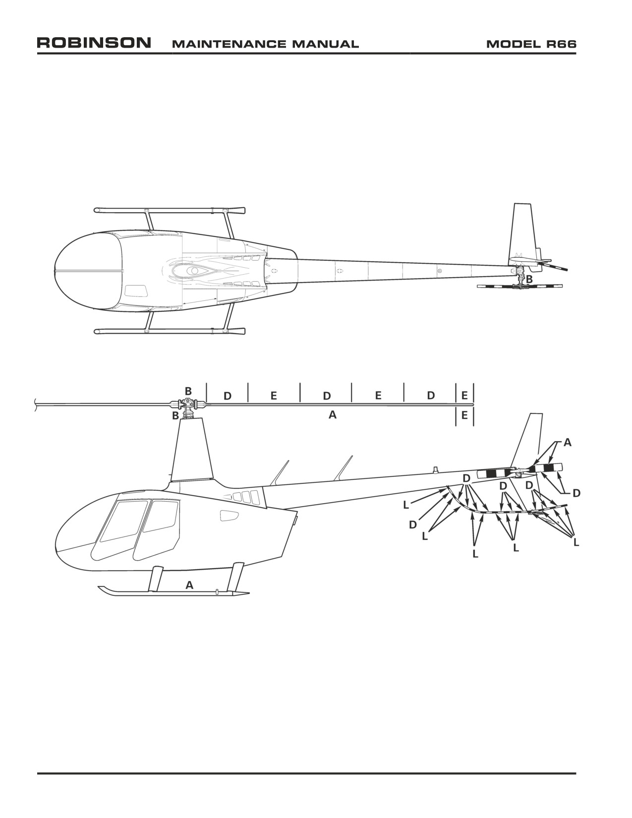
FIGURE 20-3 FINISH CODE LOCATIONS - EXTERIOR
Page 20.20
Chapter 20 Standard Practices
25 OCT 2010
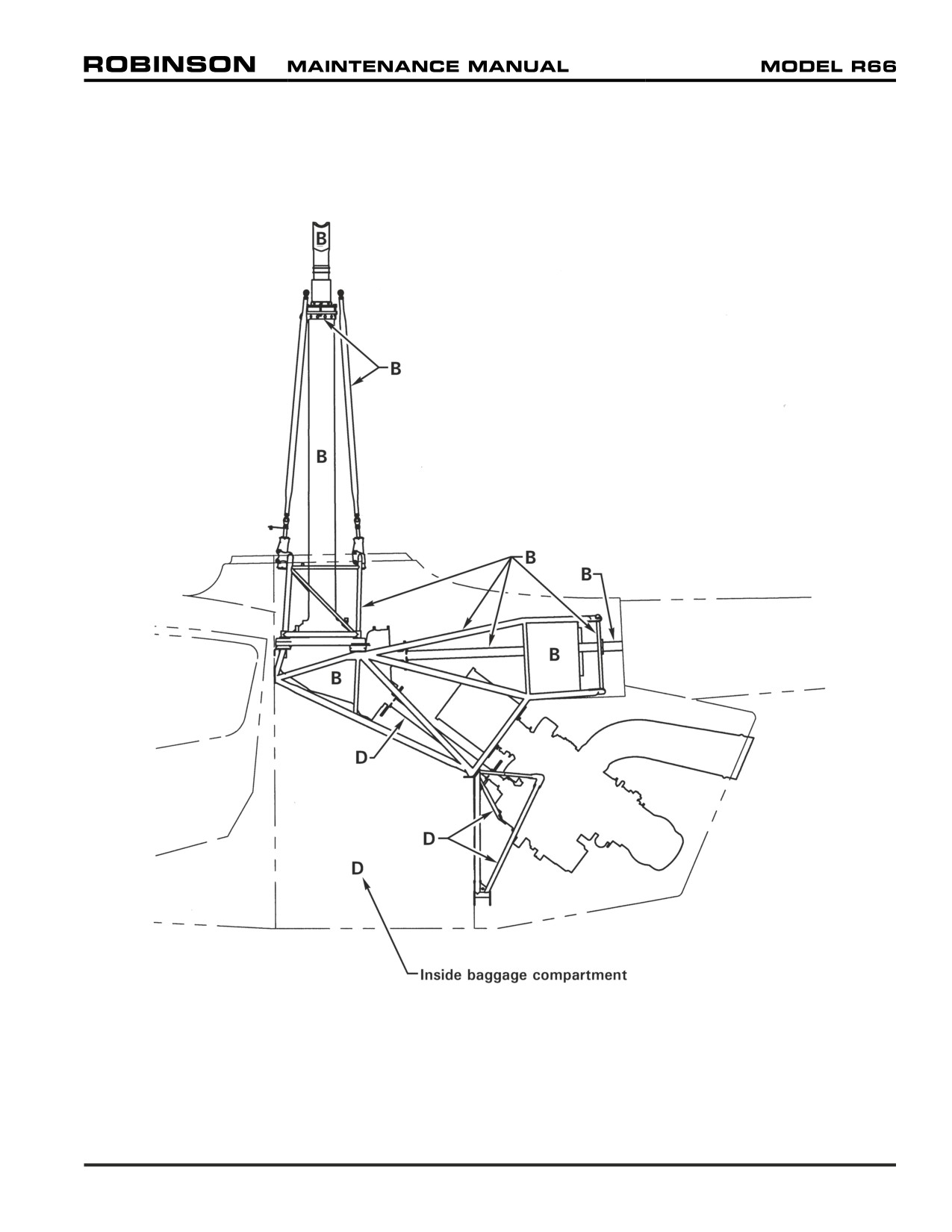
FIGURE 20-4 FINISH CODE LOCATIONS - INTERIOR
Chapter 20 Standard Practices
Page 20.21
20-78 Lubricants
RHC Part No.
Mfr. Part No.
Manufacturer
A257-1
101
Southwestern Petroleum Corp.
(general purpose grease)
Fort Worth, TX
A257-3
Aero Shell 14
Shell Oil Co.
MIL-G-25537 (grease)
A257-4
Dexron II or
Quaker State or Pennzoil
Dexron II/Mercon or
Dexron III/Mercon
(automatic transmission fluid)
A257-5
3120
Sta-Lube, Inc.
(water-resistant grease)
Compton, CA
11402
Lubrimatic
(water-resistant grease)
Buffalo Grove, IL
A257-6
Fuelube
Fleet Supplies Inc.
(fuel-resistant grease)
Cleveland, OH
EZ Turn
United-Erie Div. of Interstate Chemical Co.
(fuel-resistant grease)
Erie, PA
A257-7
Lubri-Kote Type A 1040 CR
Mealey Ind. Lubricants
(dry film lubricant)
Cleveland, OH
A257-8
P-80
International Products Corp.
(rubber lubricant)
Trenton, NJ
A257-9
Silver Grade
Loctite Corp.
(anti-seize)
Newington, CT
A257-15
MIL-PRF-5606
Any
(hydraulic fluid)
A257-19
111
Dow Corning Corp.
(valve lube & sealant compound)
Midland, MI
A257-20
Pag Oil
Apollo America Corp.
Daphne Hermetic PR
Southfield, MI
A257-21
P-16
Panef Corp.
(petrolatum lubricant)
Milwaukee, WI
A257-22
Mobil SHC 629
Exxon Mobil Corp.
(synthetic gear oil)
A257-23
AS 5780 HPC
Any
Class HTS (turbine oil)
Page 20.22
Chapter 20 Standard Practices
20-79 Adhesives and Sealants
RHC Part
Description
Color
Mfr. Part No.
Manufacturer
No.
B270-1
Sealant - polysulfide, fuel resistant
Gray
FS-8907 B-2
PPG Aerospace
(2-part)
Glendale, CA
Sealant - polysulfide, fuel resistant
Gray
AC-350 B-2
Advanced Chemistry
(2-part)
& Technology Inc.,
Garden Grove, CA
B270-5
Sealant - synthetic rubber putty
White
Q4-2805
Dow Corning Corp.
(1-part)
Light Gray
94-031
Midland, MI
B270-6
Sealant & lubricant - thread
Gray
Titeseal 55
Radiator Spec. Co.
(1-part)
Charlotte, NC
B270-8
Adhesive - rubber, nitrile/acetone
Tan
C 160
Stabond Corp.
(1-part)
Gardena, CA
B270-9
Adhesive - epoxy, structural,
Gray
2216 B/A
3M Co.
flexible (2-part)
St. Paul, MN
B270-10
Adhesive/sealant - threadlocker,
Red
271
Henkel Loctite Corp.
anaerobic (tight-fits) (1-part)
Rocky Hill, CT
B270-11
Adhesive/sealant - threadlocker,
Red
277
Henkel Loctite Corp.
anaerobic (loose-fits) (1-part)
Rocky Hill, CT
B270-12
Sealant - electrical potting (2-part)
Any color
MIL-PRF-8516
Any
except red
Type II, Class 2,
Category A or B
B270-13
Sealant - silicone rubber, electronic
Translucent
3145
Dow Corning Corp.
use (1-part)
Midland, MI
B270-14*
Adhesive - foam, neoprene/water
White
100 Neutral
3M Co.
(1-part)
Lavender
100 Lavender
St. Paul, MN
B270-15
Adhesive - plastic, for vinyl
Clear
2262
3M Co.
(1-part)
St. Paul, MN
B270-17
Adhesive - cyanoacrylate, instant
Clear
Super Bonder
Henkel Loctite Corp.
(1-part)
495
Rocky Hill, CT
B270-18
Adhesive - weather strip (1-part)
Black
051135-08008
3M Co.
St. Paul, MN
B270-19
Adhesive - epoxy structural, rigid
Green
1838 B/A
3M Co.
(2-part)
St. Paul, MN
B270-20
Adhesive/sealant - threadlocker,
Purple
222 or 222MS
Henkel Loctite Corp.
anaerobic, non-permanent (1-part)
Rocky Hill, CT
B270-21
Protectant - corrosion, non-drying
Lt. Amber
LPS 3
LPS Laboratories, Inc.
(1-part)
Tucker, GA
B270-22
Protectant - corrosion, drying
Amber
LPS Hardcoat
LPS Laboratories, Inc.
(1-part)
Tucker, GA
* B270-8 may be substituted for B270-14.
Chapter 20 Standard Practices
Page 20.23
20-79 Adhesives and Sealants (continued)
RHC Part
Description
Color
Mfr. Part No.
Manufacturer
No.
B270-23
Sealant - gasket (1-part)
Brown
GM3H
Perfect Seal
(Gasket Maker #4)
Sealant - gasket (1-part)
Brown
JV66B
Dana Corp.;
Churubusco, IN
(Victor Reinz Brand)
B270-24
Activator/Primer -
Translucent
7649
Henkel Loctite Corp.
Anaerobic adhesive (1-part)
Green
Rocky Hill, CT
B270-25
Clear Coat - automotive
Clear
Clear Coat
Automotivetouchup
touch up, brush in bottle
Touch up Bottle
Harahan, LA
(1-part)
B270-26
Sealant - Polysulfide,
Black
AC-251B-1
Advanced Chemistry &
window glazing (2-Part)
Technology Inc.,
Garden Grove, CA
20-80 Storage Limits
1. P/N B283-x hoses have a shelf storage life of 5 years. Hose service life is “on condition”,
with a maximum of 12 years or 2000 hours, whichever occurs first.
2. Elastic cords have a shelf storage life of 5 years. Elastic cord service life is “on condition”,
with a maximum of 12 years. Use invoice or FAA Form 8130 date as start date.
3. Store V-belts at less than 85ºF (30ºC), with relative humidity below 70%. Avoid solvent
and oil vapors, atmospheric contaminants, sunlight, and ozone sources (electric motors, arc
welding, ionizing air purifiers, etc.). Belt shelf life is 4 years if preceding recommendations
are followed. Use invoice date or FAA Form 8130-3 date as start date.
4. Oils and greases have a 5 year shelf life when stored and kept sealed in their original
container. Use invoice date or FAA Form 8130-3 date as start date unless the manufacturer
has marked container with manufacture date (in which case use manufacture date as start
date).
5. Rubber o-rings, seals, and gaskets have a shelf storage life of 20 quarters (5 years). Service
life is “on condition” with a maximum of 12 years. Use cure date on package as start
date.
6. Store fuel cell (bladder) in temperatures above 45ºF and below 75ºF.
Page 20.24
Chapter 20 Standard Practices
20-90 Miscellaneous Practices
20-91 Part Interchangeability
The following parts are interchangeable. Unless noted otherwise, whenever one part is
referred to in this manual, its substitute part is also permitted.
Part
Interchangeable with:
354601 & 354602
D262-1 & D262-2
AN340 nut
MS35649 nut per NASM35649 except AN340B8 nut
AN345 nut
MS35650 nut per NASM35650
AN364 nut
MS21083 nut per NASM21083
AN507 screw
MS24693 screw per NASM24693
AN509 screw
MS24694 screw per NASM24694
AN515 screw
MS35206 screw per NASM35206
AN515C screw
MS51957 screw
AN515UB screw
B567-__ screw
AN525 & AN526 screw
MS27039C screw per NASM27039
AN814 & MS24391 plug
AS5169 plug
AN815 & MS24392 union
AS5174 union
AN819 & MS20819 sleeve
AS5176 sleeve
AN822 & MS20822 elbow
AS5195 elbow
AN823 & MS20823 elbow
AS5196 elbow
AN825 & MS20825 tee
AS5197 tee
AN826 & MS20826 tee
AS5198 tee
AN894 & MS24398 bushing
AS5173 bushing
AN900 gasket
MS35769 gasket per AS35769
AN924 nut & MS24400 nut
AS5178 nut
AN931 grommet
MS35489 grommet
AN935 lockwasher
B332-__ lockwasher
AN936 lockwasher
MS35335 lockwasher
AN960-4L washer
NAS1149FN416P washer
AN960-4 washer
NAS1149FN432P washer
AN960-6L washer
NAS1149FN616P washer
AN960-6 washer
NAS1149FN632P washer
AN960-8L washer
NAS1149FN816P washer
AN960-8 washer
NAS1149FN832P washer
AN960-10L washer
NAS1149F0332P washer
AN960-10 washer
NAS1149F0363P washer
AN960-416L washer
NAS1149F0432P washer
AN960-416 washer
NAS1149F0463P washer
AN960-516L washer
NAS1149F0532P washer
AN960-516 washer
NAS1149F0563P washer
AN960-616L washer
NAS1149F0632P washer
AN960-616 washer
NAS1149F0663P washer
AN960-816L washer
NAS1149F0816P washer
AN960-816 washer
NAS1149F0832P washer
AN960-1016L washer
NAS1149F1032P washer
AN960-1016 washer
NAS1149F1063P washer
AN960PD8L washer
NAS1149DN816P washer
AN960PD416L washer
NAS1149D0416J washer
AN960PD516L washer
NAS1149D0516J washer
AN960PD616L washer
NAS1149D0616J washer
AVDEL 1693 rivet
AVDEL 1691 rivet
MS20604ML4W1 rivet
MS20604M4W1 rivet per NASM20604
MS21919DG_ clamp
MS21919WDG_ clamp or AS21919 clamp
NAS1291 nut
MS21042L_ nut per NASM21042
NAS1303 thru NAS1320 bolt
NAS6603 thru NAS6620 bolt*
NAS487 instrument nut
MS33737 Instrument nut per NASM33737
NAS679A nut
NAS1291- nut or MS21042L_ nut per NASM21042
NAS679C M nut
NAS1291C M nut
NAS696 nutplate
MS21071 nutplate per NASM21071
NAS698 nutplate
MS21073 nutplate per NASM21073
*The following bolts must be NAS1300 series only: NAS1304-17, -28, -35, -37, & -38, and NAS1305-35.
25 OCT 2010
Chapter 20 Standard Practices
Page 20.25
20-92 Thermal Fitting Parts
General Procedures for using heat to fit parts during assembly or evaluating parts that may
have been overheated in service:
Aluminum parts must not be heated above 200ºF for more than 5 minutes. Higher
temperatures or longer times adversely affect strength and corrosion properties. Scrap any
aluminum parts suspected of going above 325ºF regardless of time at temperature.
Steel parts (bare) - Maximum temperature 300ºF. Higher temperature can reduce the
strength or cause temper brittleness in some alloys.
Steel parts (cadmium plated) - Maximum temperature 300ºF. Higher temperatures
will melt the plating and adversely affect steel strength by a process called liquid metal
embrittlement.
Bearings and carburized parts such as gears, clutch shafts, and clutch housings should
not be heated above 300ºF. Higher temperatures will reduce the surface hardness and
increase wear rates.
Always heat parts in an oven with temperature control set no greater than the maximum
temperature allowed for the part.
Always attach a pyrometer and thermocouple to the smallest aluminum part in the oven.
Never depend on the oven control to determine part temperature.
Cooling a part for thermal fitting at assembly is not recommended. Water vapor from the
air will condense on the part and frequently introduce water into the assembly causing
severe internal corrosion over time.
20-93 Replacement Component Identification (Data) Plates
In order to issue a replacement component identification plate for field installation, RHC
must first receive the old identification plate in legible condition. If old identification plate
is lost or destroyed, then RHC must have an original letter (photocopies or faxes are
NOT acceptable) from customer’s Civil Aviation Authority authorizing identification plate
replacement AND stating component name, part number, and serial number for each
requested identification plate. There is a charge for each plate issued.
Identification plates may be carefully removed using a sharp plastic scraper. If necessary,
use a heat gun to soften plate adhesive. Retain in a dry, contaminate-free area until ready
for reinstallation.
Damp wipe local area with acetone or equivalent solvent prior to reinstallation. Residual
adhesive on identification plate is usually sufficient for good adhesion. If necessary, use
B270-9 adhesive or equivalent to secure.
Page 20.26
Chapter 20 Standard Practices
25 OCT 2010
CHAPTER 21
ENVIRONMENT CONTROL
Section Title
Page
21-00
Description
21.1
21-10
Ventilation
21.3
21-11
Nose Vent
21.3
21-20
Air Conditioning
21.5
21-21
Compressor Assembly
21.5
21-22
Condenser and Fan Assemblies
21.7
21-23
Evaporator Assembly
21.8
21-24
Troubleshooting
21.9
21-30
Cabin Heat
21.11
21-31
Valve Assembly and Control Rigging
21.11
21-32
Muffler Assembly
21.12
21-33
Diffuser and Tee Assemblies
21.12
Chapter 21 Environment Control
Page 21.i
Intentionally Blank
Page 21.ii
Chapter 21 Environment Control
CHAPTER 21
ENVIRONMENT CONTROL
21-00 Description
Fresh air vents are located in each door and in the nose. Door vents are opened and closed
using the knob near the vent door hinge. A rotating knob is provided to seal and lock vents
closed. For maximum ventilation, open door vents wide during hover but only one inch or less
during cruise. The rotating knob can be used to hold vents partially open.
See Chapter 52 for door vent maintenance instructions.
The fresh air inlet in the nose is opened by pulling the vent handle on the console face. Rotating
the vent handle clockwise will lock its position. Air from the nose inlet is directed along the
inside surface of the windshield for defogging as well as for ventilation.
The optional cabin air conditioning system, shown schematically in Figure 21-2, is similar to
conventional automotive and light aircraft systems. The system consists of a compressor
mounted immediately aft of the main gearbox, a condenser mounted to the vertical firewall
in the engine compartment, an evaporator mounted to the front of the center seat support, a
blower, an overhead outlet duct, and interconnecting lines and hoses. The system uses R134a
refrigerant.
The compressor is belt-driven, by a pulley mounted to the main gearbox tail rotor drive yoke
assembly, and is equipped with an electromagnetic clutch. When the system is off, the
compressor clutch is disengaged, allowing the compressor pulley to freewheel.
Cooling air for the condenser is supplied via an opening in the belly. The engine cowling air
scoop collects the necessary cooling air for the condenser during forward flight. In a hover,
electric fans help to draw cooling air through the condenser.
The evaporator blower draws warm cabin air though the evaporator inlet grill and evaporator,
where the air is cooled. Cool air is drawn through the blower and blown through ducts under
the center seat, up the cabin aft wall, and to the overhead duct.
The system is controlled by a toggle switch on the overhead duct which allows selection of off,
low, and high fan settings. The compressor is automatically engaged by switching the fan on.
A temperature (freeze) switch disengages the compressor when evaporator temperature drops
below freezing. Safety (pressure) switches disengage the compressor if excessive refrigerant
leakage occurs or if refrigerant pressure is excessive. When the collective is lowered to the
full-down position another switch disengages the compressor for 10 seconds to ensure that
aircraft performance is not affected. All circuits are protected by the 25 amp A/C circuit
breaker; the evaporator blower, the condenser fans, and the compressor clutch circuits are
further protected by fuses.
Bleed air from the engine compressor is used for cabin heat. Tubing routes hot air from the
engine to outlets forward of the tail rotor pedals and in the rear footwells. A heater control
knob located to the left of the cyclic stick actuates a valve in the aft end of the control tunnel
through a push-pull cable to control cabin heat. Because the cabin heat uses engine compressor
air, some performance degradation occurs with heat ON.
CAUTION
In case of engine fire, cabin heat should be turned off.
Chapter 21 Environment Control
Page 21.1
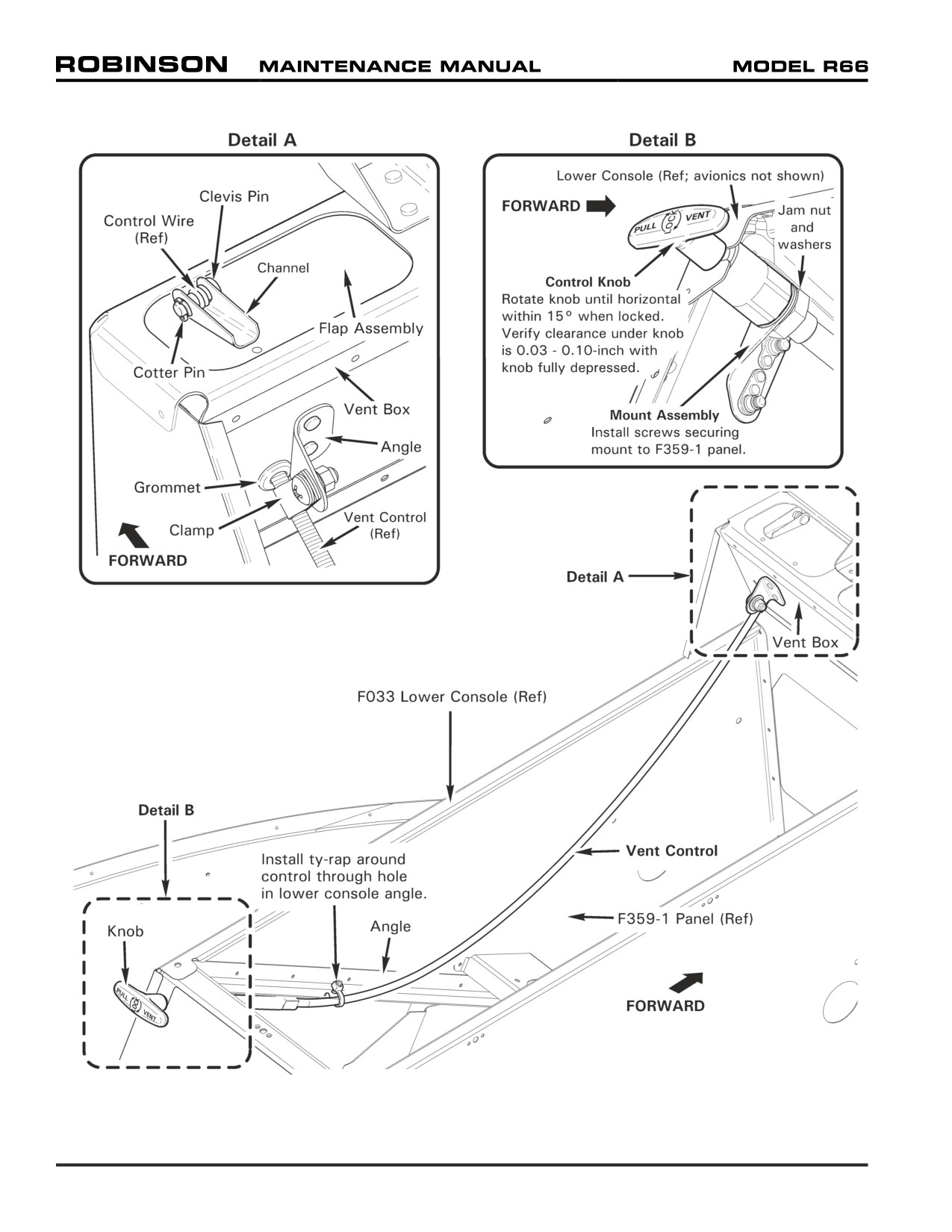
FIGURE 21-1 NOSE VENT
Page 21.2
Chapter 21 Environment Control
21-10 Ventilation
21-11 Nose Vent
Refer to R66 Illustrated Parts Catalog (IPC) Figures 21-1.
A. Removal
1. Remove hardware securing avionics face to F033-1 lower console and remove face.
Unscrew and remove radios. Remove hardware securing radio trays to lower console
and remove trays. Disconnect OAT wiring.
2. Refer to Figure 21-1. Remove screws attaching upper console to lower console and
hinge console aft. Protect instrument face with foam support or equivalent.
3. Remove and discard cotter pin securing clevis pin and C522-5 (air vent) control inner
wire to C062-1 vent box assembly channel. Remove and retain clevis pin.
4. Remove hardware securing AN742-3 clamp and control housing to vent box angle.
5. Cut and discard ty-rap securing control housing to lower console angle.
6. Remove screws securing C365-13 mount assembly to lower console and remove
control. As required, remove MS35489-4 grommet and clamp; remove jam nut
& lockwashers securing mount assembly to control housing, and remove mount
assembly.
B.
Installation
1.
Refer to Figure 21-1. As required, install C365-12 mount assembly, lockwashers,
and jam nut on C522-5 (air vent) control housing, but do not tighten jam nut. Install
AN742-3 clamp and (new, as required) MS35489-4 grommet on control housing.
2.
Position control in lower console and install screws securing mount assembly to
lower console. Verify security.
3.
Rotate control knob until horizontal within 15° when locked; tighten jam nut against
mount assembly. Verify security.
4.
Route control inner wire through C062-1 vent box assembly channel. Adjust grommet
position as required, and install clevis pin through channel and control inner wire.
Install cotter pin. Verify security.
5.
Install clamp and hardware securing clamp and control housing to vent box angle.
6.
Install ty-rap around control housing through hole in lower console angle. Cinch ty-
rap until snug without over-tightening, and trim tip flush with head.
7.
Actuate vent and adjust clamp position as required for proper vent operation. Verify
control housing does not slip through clamp when opening and closing vent. Verify
clearance under knob is 0.03-0.10 inch with knob fully depressed.
8.
Close and secure upper console. Connect OAT wiring. Install radio trays and
hardware securing trays to lower console. Verify security. Install and secure radios.
Install avionics face and hardware securing face to lower console.
Chapter 21 Environment Control
Page 21.3
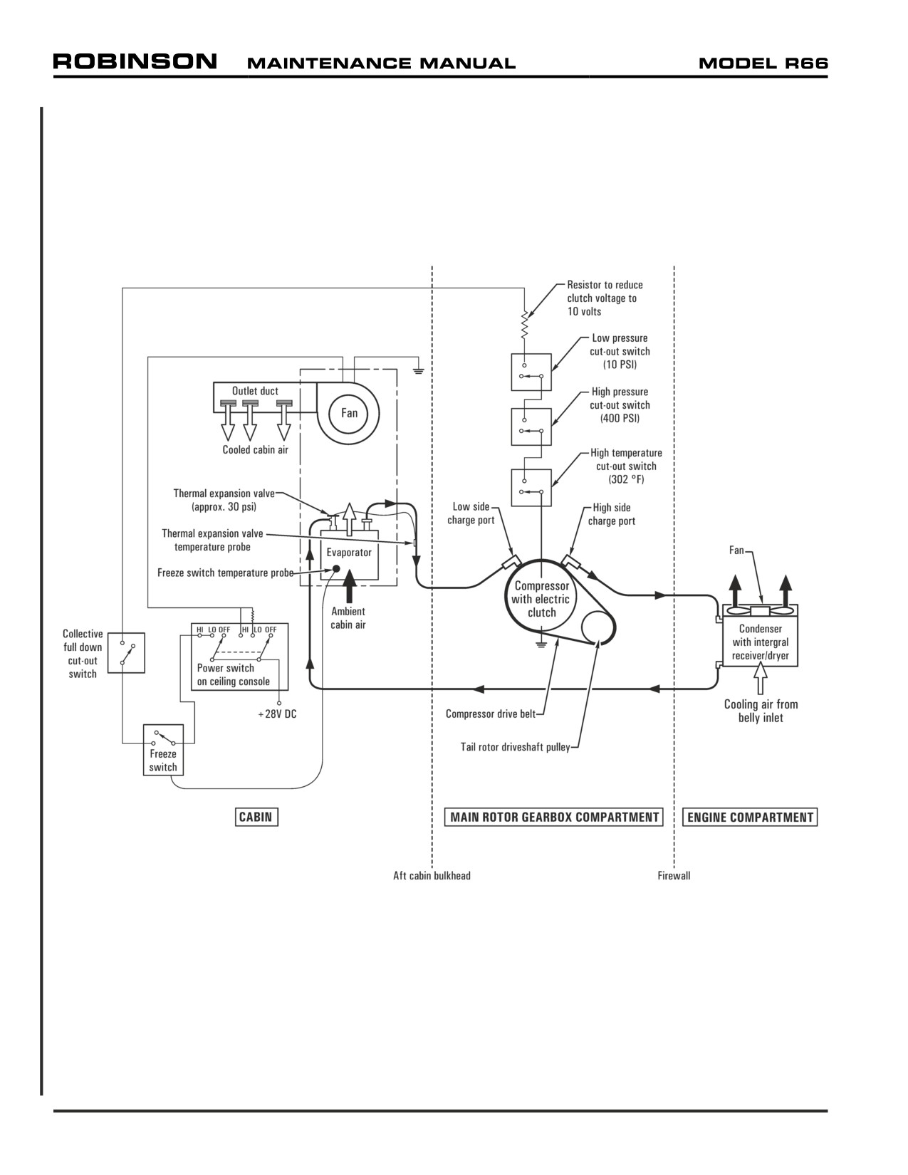
FIGURE 21-2 AIR CONDITIONING SCHEMATIC
Page 21.4
Chapter 21 Environment Control
21-20 Air Conditioning
21-21 Compressor Assembly
Refer to R66 Illustrated Parts Catalog (IPC) Figure 21-3.
A. Belt Replacement
1.
Remove tailcone cowling per Section 53-23.
2.
Remove hardware securing F196-1 tail rotor drive fan shaft to C947-3 plate
assemblies, noting hardware removed.
3.
Loosen hardware securing G777-1 compressor assembly to G781-1 arm weldment.
CAUTION
Do not use refrigerant hose assemblies or fittings to rotate
compressor. Do not rotate compressor further than necessary, to
avoid damaging system wiring and refrigerant hoses or fittings.
4.
Rotate compressor down and inboard as required to disengage B173-5 v-belt from
pulleys. Route belt around drive shaft flange and remove belt.
5.
Route new B173-5 v-belt around drive shaft flange and fit belt onto G779-1 pulley
and compressor pulley.
6.
Rotate compressor up and outboard to tension belt, then tighten hardware securing
compressor to weldment. Adjust belt until 4.5-5.5 lb of force applied mid-span
deflects belt 0.16-inch. Standard torque bolts per Section 20-32 and torque stripe
per Figure 5-1.
7.
Install hardware securing drive shaft to plate assemblies, as removed. Standard
torque bolts per Section 20-32 and torque stripe per Figure 5-1.
8.
Install tailcone cowling per Section 53-23.
Chapter 21 Environment Control
Page 21.5
21-21 Compressor Assembly (continued)
B.
Removal
1. Remove tailcone cowling per Section 53-23.
2. Turn BATTERY switch OFF. Cut and discard ty-raps as required and disconnect
compressor assembly wiring from airframe harness at connectors.
3. Recover refrigerant per Section 12-81. Remove hardware securing refrigerant hose
assemblies to G777-1 compressor assembly. Cap fittings.
4. Remove hardware securing compressor to G781-1 arm weldment and G782-1 mount
weldment and remove compressor.
C. Installation
1.
Remove G777-1 compressor assembly service port caps and completely drain oil.
Using a syringe, service compressor with 3 oz A257-20 pag oil into the high pressure
port. Install service port caps; verify security.
2.
Refer to Section 5-45. Inspect B173-5 v-belt condition and replace as required. Fit
belt around G779-1 pulley and compressor pulley, and install hardware securing
compressor to G782-1 mount weldment. Standard torque bolts per Section 20-32.
3.
Install hardware securing compressor to G781-1 arm weldment. Rotate compressor
up and outboard to tension belt, then tighten hardware securing compressor to
weldment. Adjust belt until 4.5-5.5 lb of force applied mid-span deflects belt 0.16-
inch. Standard torque bolts per Section 20-32, and torque stripe all compressor
mounting hardware per Figure 5-1.
4.
Remove caps and install refrigerant hose assemblies and hardware securing hoses to
compressor. Special torque screws per Section 20-33 and torque stripe per Figure
5-1.
5.
Connect compressor assembly wiring to airframe harness at connectors and install
ty-raps as required. Cinch ty-raps until snug without over-tightening, and trim tips
flush with heads.
6.
Perform leak detection per Section 12-83.
7.
Charge system with refrigerant per Section 12-82.
8.
Install tailcone cowling per Section 53-23.
Page 21.6
Chapter 21 Environment Control
21-22 Condenser and Fan Assemblies
Refer to R66 Illustrated Parts Catalog (IPC) Figure 21-7.
A. Removal
1. Recover refrigerant per Section 12-82.
2. Remove engine cowling per Section 53-21.
3. Turn BATTERY switch OFF. Cut and discard ty-raps as required and disconnect
G780-1 fan assembly wiring from airframe harness at connectors.
4. Remove hardware securing G786-1 box assembly to G783-1 condenser.
5. Using backup wrench, disconnect G810-1 and G811-1 line assembly b-nuts from
condenser fittings.
6. Supporting condenser, remove hardware securing condenser to G787 support
assemblies. Taking care not to damage line assemblies and condenser fittings,
carefully remove condenser. Cap fittings.
B.
Installation
1. Remove caps. Install hardware securing G783-1 condenser to G787 support
assemblies. Verify security.
2. Connect G810-1 and G811-1 line assembly b-nuts to condenser fittings. Using
backup wrench, special torque b-nuts per Section 20-33, and torque stripe per Figure
5-1.
3. Install hardware securing G786-1 box assembly to condenser. Verify security.
4. Connect G780-1 fan assembly wiring to airframe harness at connectors and install
ty-raps as required. Cinch ty-raps until snug without over-tightening, and trim tips
flush with heads.
5. Perform leak detection per Section 12-83.
6. Charge system with refrigerant per Section 12-82.
7. Install engine cowling per Section 53-21.
Chapter 21 Environment Control
Page 21.7
21-23 Evaporator Assembly
Refer to R66 Illustrated Parts Catalog (IPC) Figure 21-11.
A. Removal
1. Recover refrigerant per Section 12-82.
2. Refer to Section 6-70. Detach F931-1 seat assembly (secured via hook and loop
tape) from F474-1 cover assembly and remove seat. Remove hardware securing
cover assembly and F380-8 angle to F377-1 middle seat assembly; remove cover
and angle.
3. Cut and discard ty-raps as required and disconnect D799-7 (freeze) switch assembly
wiring from airframe harness at connector.
4. Remove screws securing G798-1 cover assembly to seat assembly. Remove
hardware securing G784-1 evaporator assembly and switch to seat assembly.
5. Using backup wrench, disconnect D795-8 line assembly and evaporator line b-nuts
from G794 hose assemblies.
6. Remove aluminum tape securing F380-7 cover to middle seat (if installed). Detach
grommet from seat assembly and carefully remove evaporator and attached
components forward through seat assembly vertical wall relief. Cap fittings.
B.
Installation
1. Remove caps. Position G784-1 evaporator assembly and associated components
in F377-1 middle seat assembly. Install screws securing evaporator and D799-7
(freeze) switch assembly to seat assembly. Install screws securing G798-1 cover
assembly to seat assembly.
2. Connect D795-8 line assembly and evaporator line b-nuts to G794 hose assemblies.
Using backup wrench, special torque hose b-nuts per Section 20-33, and torque
stripe per Figure 5-1.
3. Connect freeze switch wiring to airframe harness at connector and install ty-raps as
required. Cinch ty-raps until snug without over-tightening, and trim tips flush with
heads.
4. Perform leak detection per Section 12-83.
5. Charge system with refrigerant per Section 12-82.
6. Install screws securing F474-1 cover assembly and F380-8 angle to middle seat.
Attach F931-1 seat assembly (secured via hook and loop tape) to cover.
Page 21.8
Chapter 21 Environment Control
21-24 Troubleshooting
1. If air exiting overhead duct is not cold:
POSSIBLE CAUSE
TROUBLESHOOT/CORRECTIVE ACTION
Low Refrigerant
Recover refrigerant per Section 12-82. System should operate normally on
Charge/ Refrigerant
approximately 2.5 lb refrigerant.
Leak
If less than 2.5 refrigerant is recovered, perform leak detection per Section 12-83,
repair leaks if any, and charge system with refrigerant per Section 12-82.
Switch or Wiring
With aircraft not running, turn on Master switch and A/C switch on overhead duct
Problem Interrupting
(low or high setting ok). Have observer listen to and observe compressor clutch
Compressor Power
through cowl door. Clutch should engage (click and snap against pulley) whenever
A/C is switched on.
Check wiring at freeze switch (refer to Section 21-23), high and low pressure
switches (near compressor assembly), and full-down collective switch. Repair
any damaged wiring or connectors. Check continuity through each switch. All
switches should be closed with a properly charged system and aircraft at rest on
ground. Replace any defective switch.
Failed Compressor
Inspect belt.
V-Belt
Replace belt per Section 21-21 as required.
Insufficient
Inspect condenser installation. Verify no blockage and all seals in place.
Condenser Airflow
Remove blockage and/or repair seals to ensure airflow through core.
Extreme
Extreme temperature and humidity may result in cooling effect less than a typical
Environmental
automobile.
Conditions
No corrective action available.
2. If excessive condensation is found near evaporator assembly:
POSSIBLE CAUSE
TROUBLESHOOT/CORRECTIVE ACTION
Blocked or Kinked
Verify system is draining normally. After several minutes ground run in humid
Evaporator Drain
conditions with A/C on, water should be seen draining from the drain tube.
If water drainage is not observed, inspect drain line (refer to Section 5-45). Correct
any damaged or kinked lines. Clean sediment trap as required. Verify proper
function of check ball.
Extreme Humidity
Some condensation is unavoidable in extreme humidity.
Ensure all fresh air vents closed. Limit opening and closing cabin doors as much as
practical to limit humidity entering cabin.
Chapter 21 Environment Control
Page 21.9
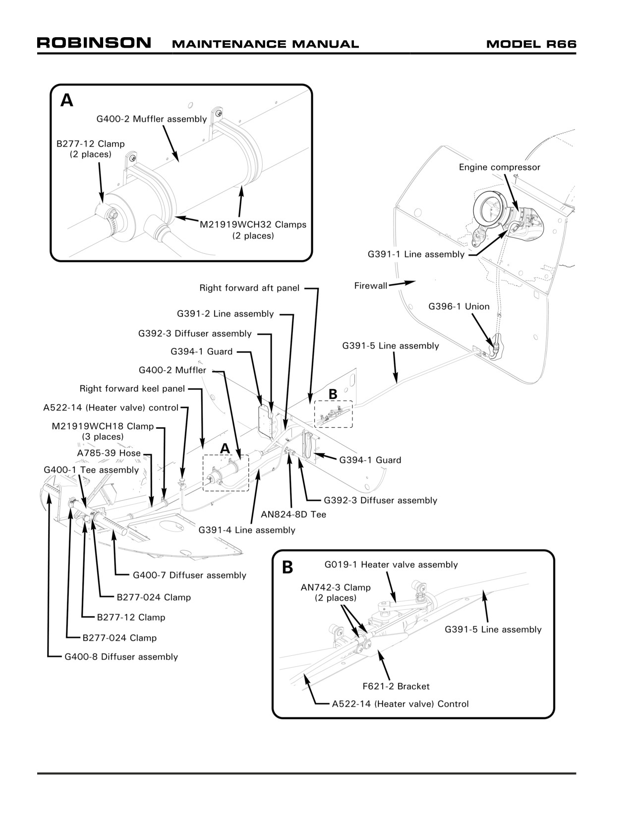
FIGURE 21-3 CABIN HEAT
Page 21.10
Chapter 21 Environment Control
21-30 Cabin Heat
21-31 Valve Assembly and Control Rigging
Refer to R66 Illustrated Parts Catalog (IPC) Figures 21-31 and 21-35.
A. Removal
1. Refer to Section 6-70. Remove hardware securing F794-1 and F794-2 (belly cover)
panels and remove panels. Remove engine cowling per Section 53-21.
2. Refer to Figure 21-3. Remove hardware securing A522-14 (heater valve) control
inner wire to G019-1 (heater) valve assembly arm.
3. Remove hardware securing AN742-3 clamps and control housing to F621-2 bracket.
4. Hinge aft right seat forward. Remove clamps, spacers, and hardware securing G391-2
and G391-5 line assemblies to aft right keel panel. Hinge seat back.
5. Loosen line assembly B-nuts from G400-2 muffler assembly & G396-1 union; disconnect
lines from valve assembly fittings and remove valve. Plug lines & cap fittings.
B.
Installation
1. Refer to Figure 21-3. Remove caps and plugs, install G019-1 (heater) valve assembly
and connect G391-2 and G391-5 line assembly B-nuts to valve assembly fittings.
Hand-tighten B-nuts at valve assembly, G400-2 muffler assembly, and G396-1 union,
but do not torque.
2. Hinge aft right seat forward. Install clamps, spacers, and hardware securing line
assemblies to aft right keel panel. Verify security. Hinge seat back.
3. Position valve assembly so F621-2 bracket is vertical within 5°; special torque line
assembly B-nuts at valve assembly, muffler assembly, and union, and torque stripe
per Figure 5-1.
4. Perform control rigging per Part C, steps 3 thru 6.
5. Install engine cowling per Section 53-21.
C. Control Rigging
1. Refer to Section 6-70. Remove hardware securing F794-1 and F794-2 (belly cover)
panels and remove panels.
2. Refer to Figure 21-3. Remove palnut and loosen nut securing A462-4 fitting and
A522-14 (heater valve) control inner wire to G019-1 (heater) valve assembly arm.
3. As required, loosen hardware securing AN742-3 clamps and control housing to
F621-2 bracket. Position end of control housing flush-0.25 inch at or beyond edge
of aft clamp and install fasteners. Verify security.
4. Refer to detail in Figure 76-3. Push heater valve knob ON then pull up slightly to
create 0.03-0.10 inch clearance under knob. Position valve assembly arm in full
open detent. Verify sufficient inner wire beyond aft edge of fitting and special
torque fitting nut per Section 20-33.
5. Install fitting palnut, standard torque per Section 20-32, and torque stripe per Figure
5-1. Trim control wire 0.10-0.30 inch beyond aft edge of fitting.
6. Install (belly cover) panels, and install hardware. Verify security.
Chapter 21 Environment Control
Page 21.11
21-32 Muffler Assembly
Refer to R66 Illustrated Parts Catalog (IPC) Figure 21-35.
A. Removal
1. Refer to Section 6-70. Remove hardware securing F794-1 and F794-2 (belly cover)
panels and remove panels.
2. Refer to Figure 21-3. Loosen B277-12 clamp and pull A785-39 hose off of G400-2
muffler assembly. Install temporary covers on muffler and hose openings.
3. Loosen G391-4 line assembly B-nut at AN824-8D tee; disconnect G391-2 and -4
line assemblies from muffler.
4. Remove hardware securing MS21919WCH32 clamps and muffler to forward right
keel panel and remove muffler. Plug & cap fittings. As required, remove clamps
from muffler.
B.
Installation
1. Refer to Figure 21-3. As required, install MS21919WCH32 clamps on G400-2
muffler assembly. Install hardware securing clamps and muffler to forward right keel
panel. Verify security.
2. Remove caps and plugs and connect G341-2 and G341-4 line assembly B-nuts
to muffler assembly fittings. Special torque B-nuts at AN824-8D tee and muffler
assembly, and torque stripe per Figure 5-1.
3. Remove temporary covers and slide B277-12 clamp and A785-39 hose onto muffler
assembly and tighten clamp. Verify security.
4. Install (belly cover) panels, and install hardware. Verify security.
21-33 Diffuser and Tee Assemblies
Refer to R66 Illustrated Parts Catalog (IPC) Figure 21-33.
A. Forward Diffuser and Tee Assembly Removal
1. Refer to Figure 21-3. Remove screws attaching upper console to lower console and
hinge console aft. Protect instrument face with foam support or equivalent.
2. Loosen two B277-24 clamps securing G400-1 tee assembly collars to G400-7 and
G400-8 diffuser assemblies. Slide diffusers outboard from tee and lower console
assembly.
3. Loosen B277-12 clamp securing A785-39 hose to tee assembly can weldment and
pull hose and clamp off of can.
4. Remove hardware securing MS21919WCH16 clamp and tee assembly to angle and
remove tee. As required, remove clamps from tee.
Page 21.12
Chapter 21 Environment Control
21-33 Diffuser and Tee Assemblies (continued)
B.
Forward Diffuser and Tee Assembly Installation
1. Refer to Figure 21-3. As required, install MS21919WCH16 and (two) B277-24
clamps on G400-1 tee assembly. Install tee with clamps, and install hardware
securing MS21919WCH16 clamp and tee to angle.
2. Insert G400-7 and G400-8 diffuser assemblies through lower console and into tee
assembly. Orient diffuser holes vertically within 5°, and tighten clamps (against
spacers) securing tee assembly collars to diffusers. Verify security.
3. Slide A785-39 hose and B277-12 clamp onto tee assembly can weldment and tighten
clamp. Verify security.
4. Close and secure upper console.
C. Aft Diffuser Assemblies and Tee Removal
1. Refer to Section 6-70. Remove hardware securing F794-1 (belly cover) forward
panel and remove panel.
2. Refer to Figure 21-3. Hinge aft right and left seats forward. Remove hardware
securing G394-1 guards and G392-3 diffuser assemblies to aft seat assemblies and
remove guards. Hinge seats back.
3. Disconnect diffuser assembly B-nuts from AN824-8D tee and remove diffusers. As
required, disconnect G391-4 line assembly B-nut from tee and remove tee. Cap
fittings.
D. Aft Diffuser Assemblies and Tee Installation
1. Refer to Figure 21-3. As required, remove caps, install AN824-8D tee, and connect
G391-4 line assembly B-nut, but do not torque.
2. Remove caps and install G392-3 diffuser assemblies; connect diffuser assembly
B-nuts to tee, but do not torque. Hinge aft right and left seats forward and install
hardware securing diffusers to aft seat assemblies. Special torque line assembly and
diffuser B-nuts per Section 20-33, and torque stripe per Figure 5-1.
3. Install G394-1 guards and hardware securing guards to aft seat assemblies. Verify
security. Hinge seats back.
4. Install (belly cover) panel, and install hardware. Verify security.
Chapter 21 Environment Control
Page 21.13
Intentionally Blank
Page 21.14
Chapter 21 Environment Control
CHAPTER 25
FURNISHINGS
Section
Title
Page
25-00
Description
25.1
25-10
Seat Harnesses
25.3
25-11
Seat Harness Removal
25.3
25-12
Seat Harness Installation
25.4
25-20
Seat Assemblies and Back Rests
25.5
25-21
Seat Assembly Removal and Installation
25.5
25-22
Back Rest Assembly Removal and Installation
25.5
25-23
Back Rest Cushion Replacement
25.5
25-30
Carpet
25.7
25-40
Insulation (Foam and Headliner)
25.8
25-50
General Maintenance
25.8
25-51
Pilot's Operating Handbook (POH) Strap Replacement . .
25.8
25-52
License Holder Replacement
25.9
25-53
Map Pocket Replacement
25.9
25-60
Emergency Equipment
25.10
25-61
Emergency Locator Transmitter (ELT)
25.10
25-62
Fire Extinguisher
25.11
Chapter 25 Furnishings
Page 25.i
Intentionally Blank
Page 25.ii
Chapter 25 Furnishings
CHAPTER 25
FURNISHINGS
25-00 Description
The seats are not adjustable but the pilot-side pedals are adjustable. Each helicopter is supplied
with a cushion which can be placed behind the pilot to position him forward. This allows
shorter pilots to reach the pedals, the cyclic stick in its most forward position, and the controls
on the center console.
Each seat is equipped with a combined seat belt and inertia reel shoulder strap. The inertia reel
is normally free but will lock if there is sudden movement as would occur in an accident.
Five-point harnesses are optional for the front seats. The five-point harness is equipped with
a webbing stop located above the inertia reel. The stop limits shoulder strap retraction and
should be adjusted so the straps are comfortable without excessive slack.
The main baggage compartment is located between the cabin and the engine compartment. It
is accessed via a large door on the aircraft right side. The cowl door annunciator illuminates
to warn the pilot when the door is not latched. A light illuminates the compartment when
the battery switch is ON. Tie down anchors are provided for securing items in the baggage
compartment. Observe placarded weight limits. Placard locations and illustrations are given
in Chapter 11.
Additional compartments are located under each seat except the center rear seat. Seat cushions
hinge forward for access to these compartments. Do not load these compartments above
the maximum fill lines. The lines indicate required crush space for the seats in an accident.
Baggage compartment dimensions are given in Chapter 6.
WARNING
Never repair or modify seat assemblies, including seat assembly
fabric, seat pans, or hook and loop tape (Velcro) securing fabric
to seat pans. Seat assembly energy-absorption design is critical
to occupant safety. To preserve crashworthiness, maintenance
is limited to seat assembly replacement.
Chapter 25 Furnishings
Page 25.1
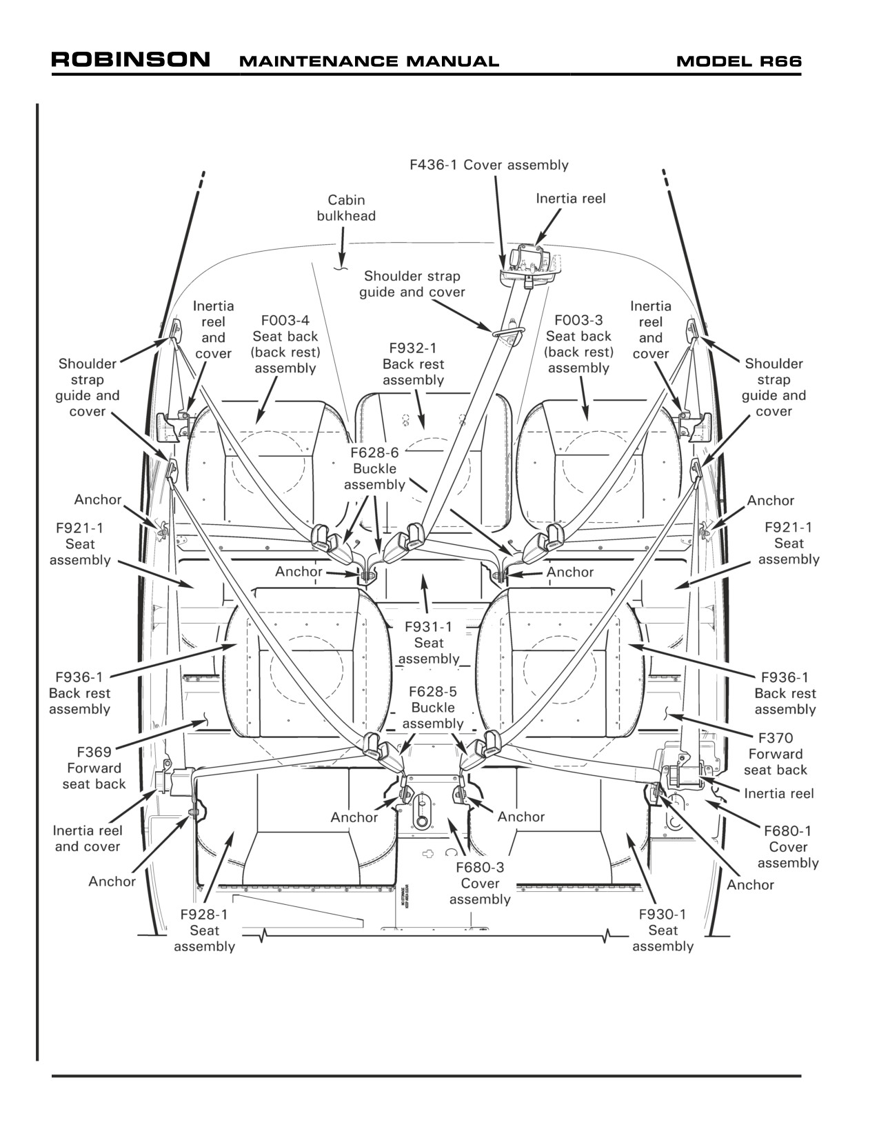
FIGURE 25-1 SEAT HARNESSES, SEAT ASSEMBLIES, AND BACK RESTS
Page 25.2
Chapter 25 Furnishings
25-10 Seat Harnesses
Refer to R66 Illustrated Parts Catalog (IPC) Figures 25-3 and 25-5. Refer to Figures 25-9, 25-
11, and 25-13 for optional Five-Point Harness Installation.
25-11 Seat Harness Removal
A. Forward Seat Harness (Standard)
1. Refer to Figure 25-1. Remove F680-1 and F680-3 collective cover assemblies; hinge
seat assemblies forward.
2. Remove hardware securing each F628-5 buckle assembly to inboard anchor, and
hardware securing each lap belt fitting to outboard anchor.
3. Remove shoulder strap guide covers and hardware securing guides to door frames.
4. Remove right side inertia reel cover and hardware securing reels to F369 and F370
forward seat backs. Remove seat harnesses.
B.
Five-Point Harness (Optional, not shown; for forward seats only)
1. Remove screws securing F424-1 bumper assembly to F423-4 tube assembly and
remove bumper.
2. Refer to Figure 25-1. Remove F680-1 and F680-3 collective cover assemblies; hinge
seat assemblies forward.
3. Remove hardware securing lap belts to inboard and outboard anchors. Remove
hardware securing fifth-point belts to seat boxes.
4. Remove hole plugs, then remove inertia reel covers and hardware securing reels to
F369 and F370 forward seat backs. Remove five-point harnesses.
C. Aft Left and Right Seat Harness
1. Refer to Figure 25-1. Remove F931-1 seat assembly; hinge left and right seat
assemblies forward.
2. Remove hardware securing each F628-6 buckle assembly to inboard anchor, and
hardware securing each lap belt fitting to outboard anchor.
3. Remove shoulder strap guide covers and hardware securing guides to door frames.
4. Remove inertia reel covers and hardware securing reels to cabin bulkhead.
D. Center Seat Harness
1. Remove tailcone cowling per Section 53-23.
2. Refer to Figure 25-1. Remove F931-1 seat assembly; hinge left and right seat
assemblies forward.
3. Remove hardware securing F628-6 buckle assembly to inboard right side anchor and
hardware securing lap belt fitting to inboard left side anchor.
4. Remove shoulder strap guide cover and hardware securing guide to cabin bulkhead
and upper frame.
5. Remove F436-1 (headset jack) cover assembly and hardware securing inertia reel to
cabin bulkhead.
Chapter 25 Furnishings
Page 25.3
25-12 Seat Harness Installation
A. Forward Seat Harness (Standard)
1. Refer to Figure 25-1. Install hardware securing inertia reels to F369 and F370
forward seat backs. Install right side reel cover.
2. Install hardware securing shoulder strap guides to door frames. Standard torque
bolts per Section 20-32. Install guide covers.
3. Install hardware securing F628-5 buckle assemblies to inboard anchors, and lap belt
fittings to outboard anchors. Position buckle swage between two forward rivets.
Standard torque bolts per Section 20-32.
4. Install F680-1 and F680-3 collective cover assemblies.
B.
Five-Point Harness (Optional, not shown; for forward seats only)
1. Attach inertia reels to F369 and F370 forward seat backs. Install covers and hole
plugs. Verify security.
2. Attach lap belt fittings to inboard and outboard anchors. Standard torque bolts per
Section 20-32.
3. Attach fifth point belts to seat boxes.
4. Refer to Figure 25-1. Install F680-1 and F680-3 collective cover assemblies; hinge
seat assemblies forward.
5. Position F424-1 bumper assembly on F423-4 tube assembly and install screws.
Verify security.
C. Aft Left and Right Seat Harness
1. Refer to Figure 25-1. Install hardware securing inertia reels to cabin bulkhead.
Install reel covers.
2. Install hardware securing shoulder strap guides to door frames. Standard torque
bolts per Section 20-32. Install guide covers.
3. Install hardware securing F628-6 buckle assemblies to inboard anchors, and lap belt
fittings to outboard anchors. Standard torque bolts per Section 20-32.
4. Install F931-1 seat assembly.
D. Center Seat Harness
1. Refer to Figure 25-1. Install hardware securing inertia reel to cabin bulkhead. Install
F436-1 (headset jack) cover assembly. Verify security.
2. Install hardware securing shoulder strap guide to cabin bulkhead and upper frame.
Standard torque bolt per Section 20-32. Install guide cover.
3. Install hardware securing F628-6 buckle assembly to inboard right side anchor, and lap
belt fitting to outboard left side anchor. Standard torque bolts per Section 20-32.
4. Install F931-1 seat assembly.
5. Install tailcone cowling per Section 53-23.
Page 25.4
Chapter 25 Furnishings
25-20 Seat Assemblies and Back Rests
Refer to R66 Illustrated Parts Catalog (IPC) Figure 25-1.
25-21 Seat Assembly Removal and Installation
WARNING
Never repair or modify seat assemblies, including seat assembly
fabric, seat pans, or hook and loop tape (Velcro) securing fabric
to seat pans. Seat assembly energy-absorption design is critical
to occupant safety. To preserve crashworthiness, maintenance
is limited to seat assembly replacement.
A. Seat Assembly
1. Refer to Figure 25-1. Remove or install hardware securing forward hinge to seat
box.
B. Center Seat Assembly
1. Refer to Figure 25-1. Center seat assembly attaches and detaches to and from the seat
box via hook and loop tape (Velcro).
25-22 Back Rest Assembly Removal and Installation
A. Aft Left and Right Back Rest Assembly
1. Refer to Figure 25-1. Remove or install hardware securing back rest assembly to
cabin bulkhead.
B. Center Back Rest Assembly
1. Refer to Figure 25-1. Detach back rest assembly hook and loop tape (Velcro) at
bottom; slide back rest assembly up and out of keyhole slots.
2. Install back rest assembly in keyhole slots and slide down. Press firmly on back rest
assembly hook and loop tape (Velcro) at bottom. Verify security.
25-23 Back Rest Cushion Replacement
A. Forward Back Rest
1. Refer to Figure 25-1. Drill out rivets securing back rest cushion to seat back panel
and deburr holes. Remove cushion.
2. Remove old adhesive residue from back rest support tube with plastic wedge. Wipe
surface with clean cloth, wet with acetone.
3. Center and straighten new cushion on seat back panel. Match drill seat back panel
#30 holes through cushion panel and deburr. Clean up debris.
4. Attach back rest cushion to seat back panel with rivets.
5. Apply B270-18 adhesive to underside of back rest cushion flap and to mating portion
of support tube. Pull flap around tube, smooth wrinkles, and trim excess flap.
Remove excess adhesive prior to curing.
Chapter 25 Furnishings
Page 25.5
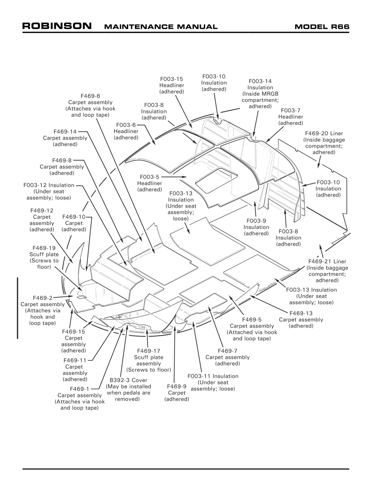
FIGURE 25-2 CARPET AND INSULATION
Page 25.6
Chapter 25 Furnishings
25-23 Back Rest Cushion Replacement (continued)
B. Aft Left and Right Back Rest
1. Refer to Figure 25-1. Remove back rest assembly per Section 25-22.
2. Drill out rivets securing back rest cushion to seat back panel and deburr holes.
Remove cushion.
3. Center and straighten new cushion on seat back panel. Match drill seat back panel
#30 holes through cushion panel and deburr. Clean up debris.
4. Attach back rest cushion to seat back panel with rivets.
5. Install back rest assembly per Section 25-22.
25-30 Carpet
Refer to R66 Illustrated Parts Catalog (IPC) Figure 25-15.
A. Forward (Floor) Carpet Assembly Removal
1. Refer to Figure 25-2. Remove adjustable and/or removable pedals, as required.
2. Remove hardware securing scuff plates (and carpet) to cabin floor. Detach carpet from
floor via hook and loop tape (Velcro).
B.
Forward (Floor) Carpet Assembly Installation
1. Refer to Figure 25-2. Attach carpet to floor via hook and loop tape (Velcro).
2. Install scuff plates; install B392-3 left-side cover (may be installed when pedals are
removed), as required.
3. Install adjustable and/or removable pedals, as required.
C. Aft (Floor) Carpet Assembly Removal and Installation
1. Refer to Figure 25-2. Attach or detach carpet to and from floor via hook and loop tape
(Velcro).
D. Carpet and Liner
CAUTION
Use caution when removing adhered carpet if carpet is intended
for reuse.
1. Removal
a. Starting at corners, gently peel back carpet by hand, or with plastic wedge or putty
knife.
b. Dampen old adhesive with Dupont Prep-Sol (or equivalent) to facilitate removal.
2. Installation
a. Verify proper carpet fit. Trim as required (do not trim carpet welt).
b. Apply B270-8 adhesive to bonding surface and carpet backing. Press carpet to
surface, smooth wrinkles, and remove excess adhesive prior to curing.
Chapter 25 Furnishings
Page 25.7
25-40 Insulation (Foam and Headliner)
Refer to R66 Illustrated Parts Catalog (IPC) Figure 25-17.
A. Removal
NOTE
Use caution not to damage surface underneath insulation when
removing insulation with tools.
NOTE
Insulation is installed using adhesive, except under seat
assemblies. Order new insulation as required; reuse of removed
insulation is not recommended.
1. Peel off insulation by hand.
2. Using plastic wedge or putty knife, carefully remove residual insulation
and
old
adhesive.
3. Wipe bonding surface with clean cloth, wet with acetone.
B.
Installation
1. Verify proper insulation fit. Trim as required.
2. Apply B270-8 adhesive to bonding surface and insulation backing. Press insulation to
surface, smooth wrinkles, and remove excess adhesive prior to curing.
25-50 General Maintenance
25-51 Pilot's Operating Handbook (POH) Strap Replacement
Refer to R66 Illustrated Parts Catalog (IPC) Figure 25-19.
A. Removal
1. Remove POH.
2. Drill out rivets securing POH retaining strap to cabin right side and remove strap.
Deburr holes and clean up debris.
B. Installation
1. Cleco POH retaining strap to cabin right side holes. Remove clecos and install rivets.
Verify security.
2. Install POH.
Page 25.8
Chapter 25 Furnishings
25-52 License Holder Replacement
Refer to R66 Illustrated Parts Catalog (IPC) Figure 25-11.
A. Removal
1. Remove aircraft documents from license holder.
2. Drill out rivets securing license holder to cabin under left side windshield frame and
remove license holder. Deburr holes and clean up debris.
B. Installation
1. Cleco license holder to cabin holes under left side windshield frame. Remove clecos
and install rivets. Verify security.
2. Insert aircraft documents into holder and tuck upper flap into frame.
25-53 Map Pocket Replacement
Refer to R66 Illustrated Parts Catalog (IPC) Figure 25-11.
A. Removal
1. Drill out rivets securing map pocket to front wall of forward seat box. Remove
pocket, washers, and retaining strips. Deburr holes and clean up debris.
B. Installation
1. Fold (long) outboard pocket edge around (long) A913-1 strip, align holes, and align
holes with front of forward seat box. Cleco in place.
2. Pull material taut, fold (short) inboard pocket edge around (short) A913-2 strip, align
holes, and align holes with front of forward seat box. Cleco in place. Trim excess
material.
3. Remove clecos and install washers and rivets.
25 OCT 2010
Chapter 25 Furnishings
Page 25.9
25-60 Emergency Equipment
25-61 Emergency Locator Transmitter (ELT)
NOTE
ELT installation is optional equipment.
A. ELT Information and Programming
Refer to Section 96-90 for ELT system description. Refer to Section 5-20 for scheduled
maintenance.
Refer to ELT Kannad 406 AF-Compact/406 AF-Compact (ER) Installation and Operation
Manual for maintenance requirements and procedures. Additional ELT information is
available on the RHC website at: http://www.robinsonhelicopter.com/supportelt.htm.
Register an ELT when first purchased, when contact information changes, or when
aircraft ownership, or tail number changes. For registration information, visit the
COSPAS-SARSAT website at: http://cospas-sarsat.org.
Kannad 406 AF-Compact ELTs are interchangeable between aircraft. A dongle contains
a memory chip that must be programmed with aircraft-specific information prior to
installation for the ELT to function. The dongle may be removed and shipped to RHC or
a Kannad service center for reprogramming.
B.
Transmitter Removal and Installation
The ELT activates when subjected to a significant change in velocity (as in an accident),
by remote control switch located on the cyclic control panel, or by a switch on the ELT
transmitter.
NOTE
Do not cut B359-2 releasable, reusable ty-rap.
1. To remove ELT transmitter:
a. Follow instructions hot stamped on ty-rap: "PULL RED TAB TO REMOVE."
b. Release Velcro strap and remove transmitter. Disconnect dongle & antenna lead.
2. To install ELT transmitter:
a. Connect dongle and antenna lead and install transmitter. Secure Velcro strap and
install B359-2 ty-rap.
C. Dongle Removal and Installation
1. Cut and discard ty-raps as required, disconnect dongle from plastic connector and
ELT transmitter, and remove dongle.
2. Connect programmed dongle to plastic connector and ELT transmitter, and install
ty-raps as required. Cinch ty-raps until snug without over-tightening, and trim tips
flush with heads.
Page 25.10
Chapter 25 Furnishings
25 OCT 2010
25-62 Fire Extinguisher
Refer to R66 Illustrated Parts Catalog (IPC) Figure 25-13.
NOTE
Fire extinguisher installation is optional equipment.
A. Inspection
Inspect fire extinguisher monthly according to manufacturer's instructions. Maintenance
instructions are located on extinguisher bottle. Record inspection date and findings as
required.
B.
Bracket Removal
1. Unlock fire extinguisher bracket and remove extinguisher.
2. Remove hardware securing bracket to cabin under left side windshield frame and
remove bracket.
C. Bracket Installation
1. Install hardware securing fire extinguisher bracket to cabin under left side windshield
frame. Select screw length as required to provide 0.00-0.06 inch thread exposure.
Verify security.
2. Inspect fire extinguisher per Part A.
3. Install fire extinguisher and lock extinguisher bracket.
25 OCT 2010
Chapter 25 Furnishings
Page 25.11
Intentionally Blank
Page 25.12
Chapter 25 Furnishings
25 OCT 2010
CHAPTER 28
FUEL SYSTEM
Section Title
Page
28-00
Description
28.1
28-10
Bladder Assembly
28.3
28-11
Roll-Over Vent Valves
28.6
28-12
Sump Valve
28.6
28-20
Fuel Quantity
28.7
28-21
Fuel Quantity Sender
28.7
28-22
Low-Fuel Switch Assembly
28.8
28-30
Fuel Valve
28.11
28-31
Fuel Valve Control Rigging
28.11
28-40
Fuel Flow Check
28.12
25 OCT 2010
Chapter 28 Fuel System
Page 28.i
Intentionally Blank
Page 28.ii
Chapter 28 Fuel System
25 OCT 2010
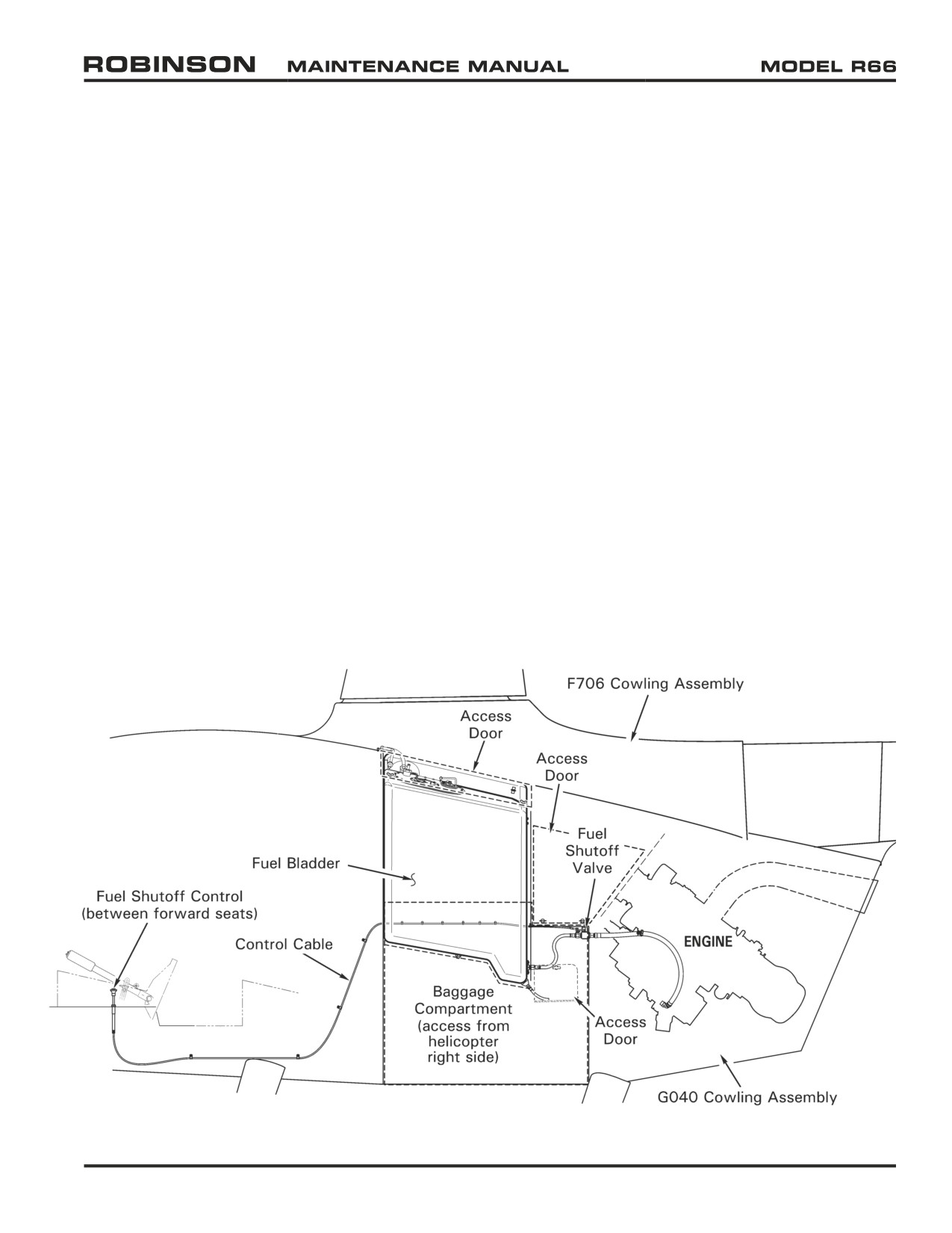
CHAPTER 28
FUEL SYSTEM
28-00 Description
This chapter includes instructions for the removal and installation of the airframe fuel system
components. Refer to RR300 Series Operation and Maintenance Manual (OMM) for engine fuel
system maintenance procedures.
A single bladder-type crash-resistant fuel cell supplies fuel via gravity flow to the engine. The
fuel cell incorporates left and right vent fittings, a filler port, a fuel gage sender, a low-fuel
switch assembly, a sump drain, and a finger strainer at the fuel outlet. The low-fuel switch
assembly activates the low fuel segment on the annunciator panel, indicating approximately
five gallons of usable fuel remaining. The vent fittings each have a roll-over valve to prevent
fuel leakage in any attitude.
The fuel cell is secured inside an aluminum structure. The filler cap is located under a cowl
door. The left and right side vent fittings are interconnected vent through two risers within the
mast fairing. A fuel valve is located on the forward side of the firewall and is controlled by a
push-pull cable control at the base of the collective stick.
The engine incorporates a fuel pump assembly with an inlet filter. A differential pressure
switch illuminates the fuel filter warning light if the filter becomes contaminated.
A single drain allows fuel sampling from the low point in the fuel cell. The drain tube is
accessible via a left side cowl door. The drain is opened by extending the plastic tube clear of
the aircraft and pushing up on the drain.
FIGURE 28-1 FUEL SYSTEM OVERVIEW
25 OCT 2010
Chapter 28 Fuel System
Page 28.1
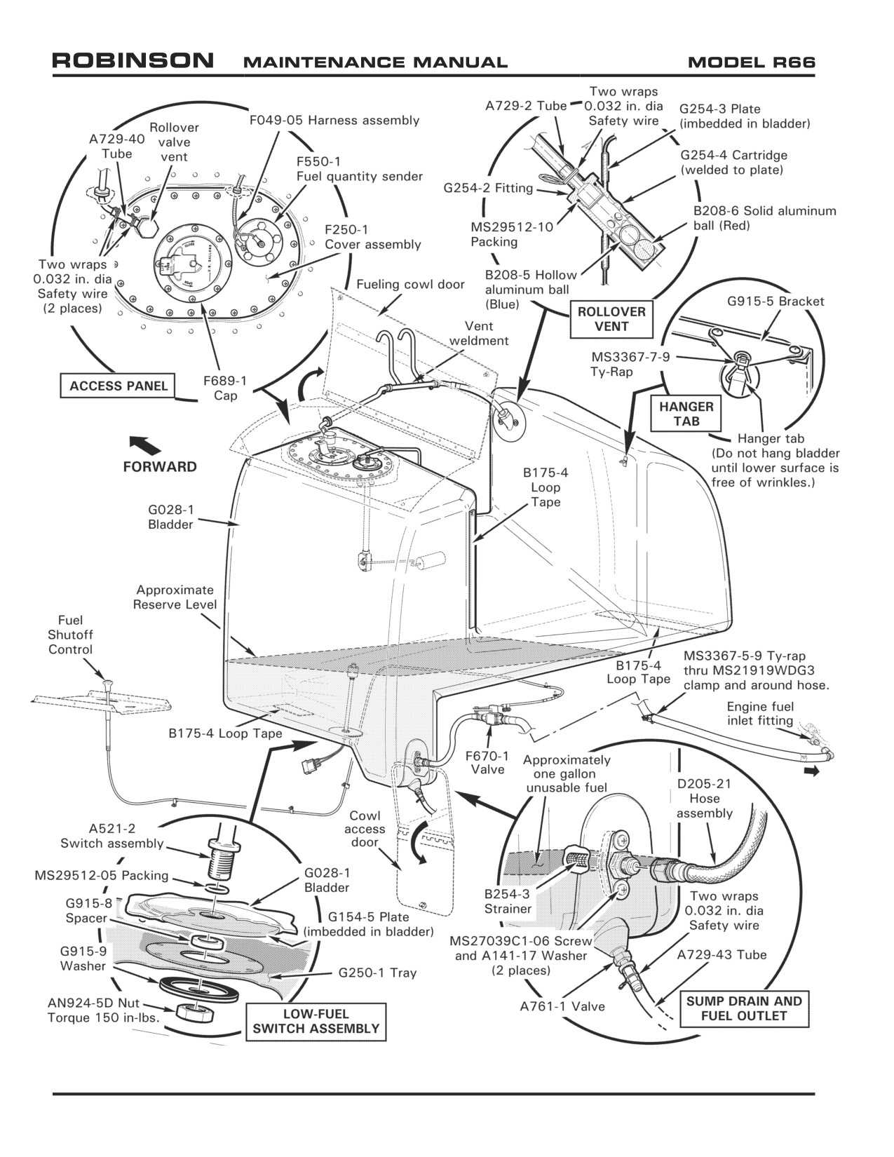
FIGURE 28-2 FUEL SYSTEM COMPONENTS
Page 28.2
Chapter 28 Fuel System
25 OCT 2010
28-10 Bladder Assembly
Refer to R66 Illustrated Parts Catalog (IPC) Figures 28-1 and 28-3.
CAUTION
G028-1 bladder assembly temperature should be above 65°F
before removing, installing, or flexing bladder.
A. Removal
1.
Defuel helicopter per Section 12-42.
2.
Remove tailcone cowling assembly per Section 53-23.
3.
Remove fuel quantity sender per Section 28-21.
4.
Refer to Figure 28-2. Cut and discard safety wire securing A729-40 tube to left roll-
over vent valve and pull tube off vent valve. Remove fasteners securing F250-1 cover
assembly to G028-1 bladder assembly and F028-1 support assembly and remove cover.
Remove and discard o-ring.
5.
Cut and discard safety wire securing A729-2 tube to right roll-over vent valve and pull
tube off vent valve. Remove screws and washers securing valve to support. Cut and
discard ty-rap securing 35486 hanger tab to G915-5 tab.
6.
Remove low-fuel switch assembly per Section 28-22. Tape bladder openings.
7.
Disconnect D205-21 (fuel outlet) hose assembly from B254-3 strainer and cap fittings.
Remove screws and washers securing strainer to support. Remove strainer and tape
bladder opening.
8.
Remove sump valve per Section 28-12.
9.
Remove hardware securing G004-4 (right side, aft fuselage) skin to cabin and remove
skin. Detach bladder hook tape from support loop tape, and remove bladder through
right side opening.
25 OCT 2010
Chapter 28 Fuel System
Page 28.3
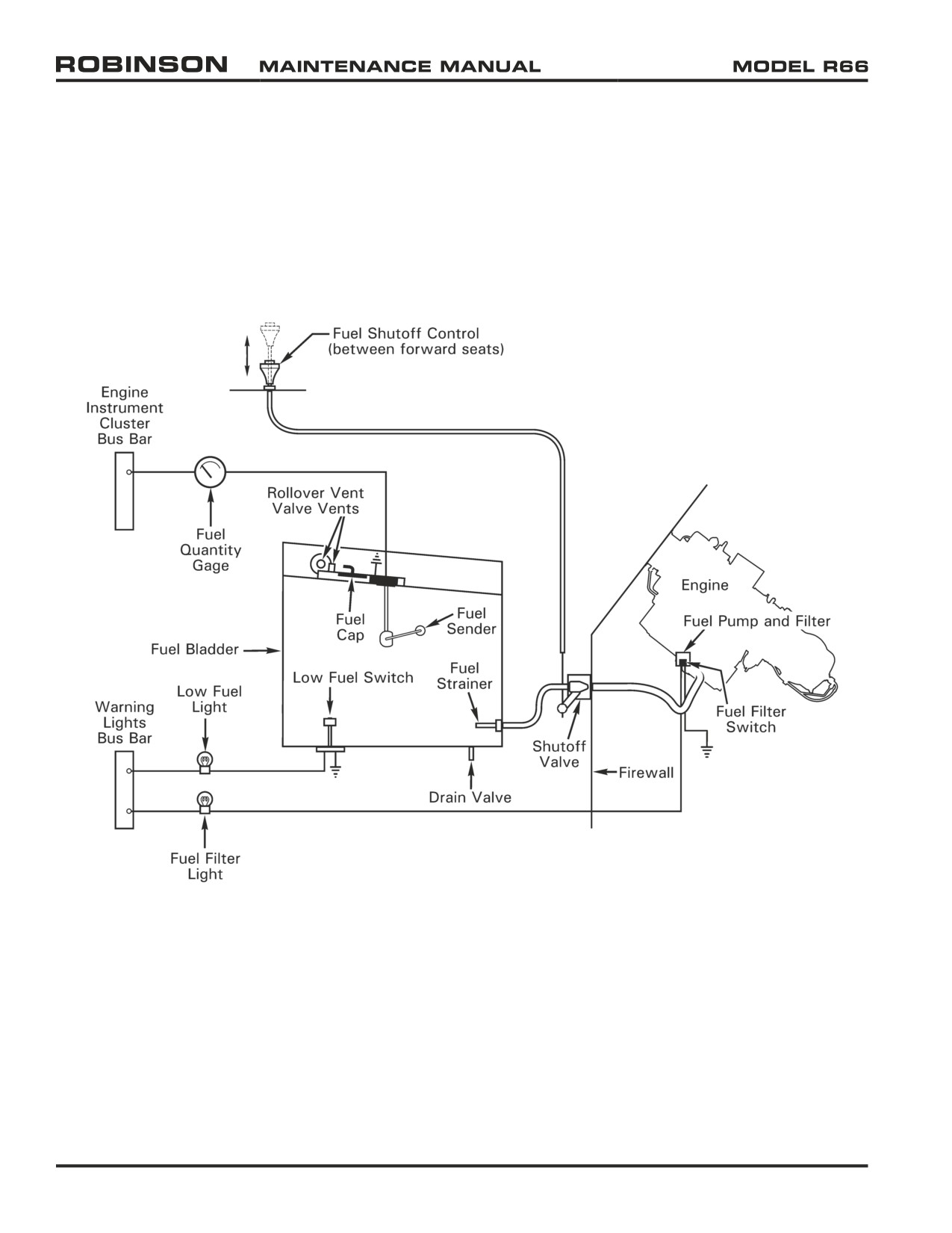
FIGURE 28-3 FUEL SYSTEM SCHEMATIC
Page 28.4
Chapter 28 Fuel System
25 OCT 2010
28-10 Fuel Bladder (continued)
B.
Installation
1.
Refer to Figure 28-2. Dust exterior of G028-1 bladder assembly and F028-1 support
assembly floor with talcum powder to facilitate bladder slippage along metal surface.
Do not allow powder to enter bladder.
2.
Note locations of hook and loop tape on bladder lower surface and support floor. Orient
bladder, fold into thirds, place in center of support, and unfold into position.
3.
Install screws and washers securing right roll-over vent valve to support. Fit A729-
2 tube onto vent valve; wrap tube with two turns 0.032-inch diameter lockwire and
safety tube to vent valve.
4.
Install MS3367-7-9 ty-rap securing 35486 hanger tab to G915-5 tab. Cinch ty-rap until
snug without over-tightening, and trim tip flush with head.
NOTE
Verify bladder is free of wrinkles across lower surface and
properly located before attaching hook and loop tape. Bladder
may be pressurized with air to 1 psi max to assist installation.
CAUTION
Avoid contaminating bladder assembly interior. Cover arms with
sleeves and use lint-free gloves when working inside bladder.
5.
Remove tape from bladder assembly openings. Insert a clean, smooth, blunt wooden
dowel through bladder service opening and press on bladder lower surface to attach
hook and loop tape. Verify security.
6.
Install low-fuel switch assembly per Section 28-22.
7.
Install screws and washers securing bladder outlet to support. Lubricate new MS29512-
06 packing using A257-6 grease and install on B254-3 strainer. Install strainer in
bladder and special torque strainer per Section 20-33.
8.
Remove caps and connect D205-21 hose assembly to strainer. Special torque B-nut per
Section 20-33 and torque stripe per Figure 5-1.
9.
Install sump valve per Section 28-12.
10.
Lubricate new MS29513-270 packing using A257-6 grease and position within recess
around bladder service opening. Install F250-1 cover assembly and install hardware
securing cover to bladder and support. Verify security. Fit A729-40 tube onto left
roll-over vent valve; wrap tube with two turns 0.032-inch diameter lockwire and safety
tube to vent valve.
11.
Install fuel quantity sender per Section 28-21.
12.
Service helicopter with two gallons of fuel per Section 12-41. Verify no leaks, especially
at bladder outlets. Install G004-4 (right side, aft fuselage) skin and install hardware
securing skin to cabin. Verify security.
13.
Perform fuel flow check per Section 28-40.
14.
Install tailcone cowling assembly per Section 53-23.
25 OCT 2010
Chapter 28 Fuel System
Page 28.5
28-11 Roll-Over Vent Valves
Refer to R66 Illustrated Parts Catalog (IPC) Figure 28-1.
WARNING
R66 roll-over vent valves contain two anodized aluminum balls,
the orientation of which are critical to vent valve function. The
blue hollow ball on top floats and seals the vent in the event of
inadvertent over-filling or in-flight sloshing. The red solid ball on
the bottom presses the hollow ball against the vent seat if the
aircraft is inverted. Valve maintenance is limited to replacing
internal packings.
A. O-ring Replacement
1. Remove tailcone cowling assembly per Section 53-23, as required.
2. Refer to Figure 28-2. Cut and discard safety wire securing A729 tube to roll-over
vent valve and pull tube off valve.
3. Remove G254-2 fitting or G254-6 retainer. Remove and discard MS29512-10
packing (G254-2 fitting only) and A215-015 o-ring.
4. Install new A215-015 o-ring in groove inside fitting or retainer. Lubricate new
MS29512-10 packing with A257-6 grease and install over G254-2 fitting threads.
5. Install fitting or retainer and special torque per Section 20-33.
6. Fit A729 tube onto roll-over vent valve; wrap tube with two turns 0.032-inch diameter
lockwire and safety tube to vent valve.
7. Install tailcone cowling assembly per Section 53-23, as required.
28-12 Sump Valve
Refer to R66 Illustrated Parts Catalog (IPC) Figure 28-3.
A. Removal
1. Defuel helicopter per Section 12-42.
2. Refer to Figure 28-2. Cut and discard safety wire securing A729-43 tube to 1250H
(sump) valve and remove tube.
3. Remove valve from G154-1 outlet assembly; tape bladder opening.
4. Actuate and lock valve to expose stem; remove and discard o-ring.
Page 28.6
Chapter 28 Fuel System
25 OCT 2010
28-12 Sump Valve (continued)
B. Installation
1. Refer to Figure 28-2. Actuate and lock 1250H (sump) valve to expose stem; install
new o-ring in stem seat.
2. Lightly coat valve threads with B270-6 sealant. Remove tape and install valve in
G154-1 outlet assembly: standard torque valve per Section 20-32 and torque stripe
per Figure 5-1.
3. Fit A729-43 tube onto valve; wrap tube with two turns 0.032-inch diameter lockwire
and safety tube to valve.
28-20 Fuel Quantity
28-21 Fuel Quantity Sender
Refer to R66 Illustrated Parts Catalog (IPC) Figure 28-1.
CAUTION
Avoid contaminating bladder interior. Cover arms with sleeves
and use lint-free gloves when working inside bladder.
A. Removal
1. Turn BATTERY switch OFF; pull GAGES circuit breaker. Open fueling cowl door.
2. Refer to Figure 28-2. Remove hardware securing G271-1 guard to F250-1 cover
assembly and remove guard.
3. Remove hardware securing F049-04 (fuel quantity sender) electrical harness wiring
to F550-1 sender.
4. Remove hardware securing sender to cover assembly. Carefully pull sender lever
through cover assembly opening. Tape bladder opening, and close fueling cowl
door.
B. Installation
1. Turn BATTERY switch OFF; pull GAGES circuit breaker. Open fueling cowl door.
2. Refer to Figure 28-2. Remove tape and install F550-1 fuel quantity sender and
15-423 gasket (supplied with new sender) in F250-1 cover assembly by carefully
lowering sender lever through opening.
3. Install hardware securing sender to cover. Special torque bolts in criss-cross pattern
per Section 20-33, and torque stripe per Figure 5-1.
4. Install F049-04 (fuel quantity sender) electrical harness wiring on sender studs, install
nuts, and special torque per Section 20-33. Install (different size) palnuts, special
torque per Section 20-32, and torque stripe per Figure 5-1.
5. Calibrate fuel quantity sender per Part C.
25 OCT 2010
Chapter 28 Fuel System
Page 28.7
28-21 Fuel Quantity Sender (continued)
C. Calibration
1. Defuel helicopter per Section 12-42.
2. Pull fuel valve knob OFF. Service helicopter with 19.4 gallons of fuel per Section
12-41.
3. Push in GAGES circuit breaker, turn BATTERY switch ON, and read fuel quantity
gage. Verify gage reads one-half needle width to one & one-half needle widths
below one-quarter mark. If fuel gage indication is correct, proceed to step 5.
4. If fuel gage indication is incorrect, remove fuel quantity sender per Part A. Slightly
bend sender lever up for a gage that reads too high, or down for a gage that reads
too low. Install fuel quantity sender per Part B.
5. Turn BATTERY switch OFF; push fuel valve knob ON.
6. Install G271-1 guard and hardware securing guard to F250-1 cover assembly. Verify
security. Close fueling cowl door.
28-22 Low-Fuel Switch Assembly
Refer to R66 Illustrated Parts Catalog (IPC) Figure 28-3.
NOTE
As required, remove fuel quantity sender per Section 28-21 and
F250-1 cover assembly per Section 28-10, to facilitate A521-2
low-fuel switch assembly removal/installation.
CAUTION
Avoid contaminating bladder interior. Cover arms with sleeves
and use lint-free gloves when working inside bladder.
A. Removal
1. Defuel helicopter per Section 12-42.
2. Refer to Section 6-70. Open baggage compartment door. Remove hardware securing
G248-1 (baggage compartment) cover and remove cover.
3. Refer to Figure 28-2. As required, cut and discard safety wire securing A729-55
tube to G930-1 (low-fuel switch) drain assembly. Remove screws securing G930-4
retainer and drain assembly to G250-1 sump tray.
4. Open fueling cowl door and remove fuel cap. Carefully capture A521-2 switch
assembly body with clean mechanical fingers (avoid capturing movable float).
5. Inside baggage compartment, remove nut, washer assembly, and spacer securing
A521-2 switch assembly to tray. Disconnect F049-03 (GCU) electrical harness
wiring from switch assembly wiring at connectors.
6. Carefully pull switch assembly through fuel cap opening (avoid F550-1 [fuel quantity]
sender). Install fuel cap, and close fueling cowl door.
Page 28.8
Chapter 28 Fuel System
25 OCT 2010
28-22 Low-Fuel Switch Assembly (continued)
B. Installation
1. Install new MS29512-05 packing over switch assembly threads.
2. Refer to Figure 28-2. Remove fuel cap. Tape switch assembly wiring to 4-ft length
of lockwire; insert other end of wire through fuel cap opening and through switch
assembly opening. Carefully grip switch assembly body with mechanical fingers and
lower switch assembly to bottom of bladder. Inside baggage compartment, guide
wiring through opening, install spacer, washer assembly, and nut securing switch
assembly to G250-1 sump tray, and special torque nut per Section 20-33. Remove
tape and lockwire. Release and remove mechanical fingers, and install fuel cap.
3. Connect F049-03 (GCU) electrical harness wiring to switch assembly wiring at
connectors. Fit wiring through gap in G930-1 (low-fuel switch) drain assembly seal,
install G930-4 retainer, and install screws securing retainer and drain assembly to
tray. Verify security. Seal gap in drain assembly seal where wires pass thru using
B270-5 sealant.
4. If removed, fit A729-55 tube onto drain assembly; wrap tube with two turns 0.032-
inch diameter lockwire and safety tube to drain assembly.
5. Service helicopter with seven gallons of fuel per Section 12-41. Verify no leaks
around switch assembly mount. Open sump drain access door and verify no leaks
from (low-fuel switch) drain tube. Perform operation check per Part C.
6. Refer to Section 6-70. Install G248-1 (baggage compartment) cover and install
hardware. Verify security. Close and latch baggage compartment door.
C. Operation Check
1. Turn BATTERY switch ON.
2. Open fueling cowl door and remove fuel cap.
3. Drain fuel until float drops, or insert a clean, non-sparking rod through fuel cap
opening and gently depress A521-2 (low-fuel) switch assembly float; verify LOW
FUEL annunciator segment illuminates.
4. Remove rod, install fuel cap, and close cowl door.
5. Turn BATTERY switch OFF.
25 OCT 2010
Chapter 28 Fuel System
Page 28.9
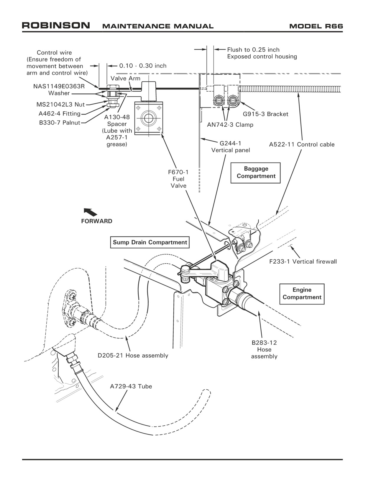
FIGURE 28-4 FUEL VALVE
Page 28.10
Chapter 28 Fuel System
25 OCT 2010
28-30 Fuel Valve
Refer to R66 Illustrated Parts Catalog (IPC) Figure 28-5.
A. Removal
1. Defuel helicopter per Section 12-42.
2. Refer to Figures 28-2 and 28-4. Open sump drain access door. Remove palnut and
loosen nut securing A462-4 fitting and A522-11 (fuel valve) control inner wire to F670-
1 fuel valve arm.
3. Disconnect D205-21 and B283-12 hose assemblies from fuel valve and cap fittings.
4. Remove screws and washers securing fuel valve to F233-1 firewall and remove fuel
valve through sump drain access door.
B.
Installation
1. Refer to Figures 28-2 and 28-4. Install F670-1 fuel valve and install screws and washers
securing valve to F233-1 firewall. Verify security.
2. Remove caps and connect D205-21 and B283-12 hose assemblies to fuel valve. Special
torque B-nuts per Section 20-33 and torque stripe per Figure 5-1.
3. Perform fuel valve control rigging per Section 28-31.
4. Perform fuel flow check per Section 28-40.
28-31 Fuel Valve Control Rigging
Refer to R66 Illustrated Parts Catalog (IPC) Figure 28-5.
1. Refer to Figures 28-2 and 28-4. Open sump drain access door. Remove palnut and
loosen nut securing A462-4 fitting and A522-11 (fuel valve) control inner wire to F670-
1 fuel valve arm.
2. Open baggage compartment door. As required, loosen hardware securing AN742-
3 clamps and control housing to G915-3 bracket. Position end of control housing
flush-0.25 inch at or beyond edge of outboard clamp and install fasteners. Verify
security.
3. Refer to detail in Figure 76-3. Push fuel valve knob ON then pull up slightly to create
0.03-0.10 clearance under knob. Position fuel valve arm in full open detent. Verify
sufficient inner wire beyond outboard edge of fitting and special torque fitting nut per
Section 20-33.
4. Pull fuel valve knob OFF and verify valve arm fully contacts OFF detent. Push fuel
valve knob ON and verify valve arm fully contacts ON detent, and meets clearance
requirement. Reposition fitting per previous steps, as required.
5. Install fitting palnut, standard torque per Section 20-32, and torque stripe per Figure
5-1. Trim control wire 0.10-0.30 inch beyond aft edge of fitting.
6. Close sump drain access door. Close and latch baggage compartment door.
25 OCT 2010
Chapter 28 Fuel System
Page 28.11
28-40 Fuel Flow Check
1. Open mast fairing per Section 53-22. Remove engine cowling per Section 53-21.
2. Refer to Figure 28-2. Attach a temporary hose to one of the vent weldment openings. With
the fuel cap installed, blow into the hose (do not use compressed air) and verify air blows
out the other vent opening. If air does not blow out the other vent, remove obstruction(s)
in vent line(s) or in fuel bladder and repeat check.
3. Defuel helicopter per Section 12-42, then service helicopter with 19.4 gallons of fuel per
Section 12-41.
4. Weigh a suitable, empty container having a volume of at least one gallon. Record weight
of empty container in table below.
5. Pull fuel valve OFF and disconnect B283-12 hose assembly from the engine fuel inlet
fitting.
6. Using a second, suitable container, push fuel valve ON and drain fuel into second container
for a few seconds to purge system of air. Then fill the weighed container for 60 seconds.
Weigh and record weight of empty container & 60 seconds of fuel flow in table below.
7. Perform the following calculation:
Combined weight of empty container & 60 seconds fuel flow:
lb
—
Subtract Weight of empty container:
lb
=
Equals Weight of 60 seconds fuel:
lb
8. Minimum fuel flow (at 19.4 gallons of fuel) is 4.75 lb/min (60 seconds). If fuel flow is less
than 4.75 lb/min, remove obstruction(s) in vent line(s), fuel bladder, fuel hoses, fuel valve,
or fuel strainer (inside bladder at outlet), and repeat check until fuel flow is satisfactory.
9. Close mast fairing per Section 53-22. Install engine cowling per Section 53-21.
Page 28.12
Chapter 28 Fuel System
25 OCT 2010
CHAPTER 32
LANDING GEAR
Section
Title
Page
32-00
Description
32.1
32-10
Landing Gear Assembly
32.1
32-20
Cross Tubes
32.5
32-30
Skid Tubes
32.7
32-31
Skid Shoes
32.8
32-32
Skid Extension Replacement
32.8
32-33
Ground Handling Wheel Support Replacement
32.8
32-40
Fairing Assemblies
32.9
32-50
Maintenance
32.9
32-60
Pop-Out Floats Installation
32.11
32-61
Cylinder Assembly
32.11
32-62
Lever Rigging and Shear-Rivet Replacement
32.17
32-63
Float Installation
32.19
32-64
System Maintenance
32.22
Chapter 32 Landing Gear
Page 32.i
Intentionally Blank
Page 32.ii
Chapter 32 Landing Gear
CHAPTER 32
LANDING GEAR
32-00 Description
A spring and yield skid type landing gear is used. Most hard landings will be absorbed
elastically. However, in an extremely hard landing, the struts will hinge up and outward as the
center crosstube yields (takes permanent set) to absorb the impact. Slight yielding of the aft
crosstube is acceptable. For tail skid height limitation, see Section 32-20. For hard landing
inspection, see Section 5-65.
Hardened steel wear shoes are mounted on the bottom of the skids. Inspect skid tubes and
skid shoes per Section 32-30, particularly if autorotation landings with ground contact have
been performed.
Pop-out float landing gear is available as optional equipment. See Section 32-60 for pop-out
float installation description.
32-10 Landing Gear Assembly
A. Removal
1.
Open cabin aft doors and baggage compartment door. Remove engine cowling per
Section 53-21.
2.
Refer to Section 6-70; remove G308-2 and two F475-6 cross tube covers. Remove
fairing assemblies per Section 32-40.
3.
Refer to Figure 32-1. Remove hardware securing A936-3 (ground) wire assembly to
aft, right landing gear attachment.
4.
Using putty knife or plastic scraper, cut sealant securing four cross tube rain caps to
landing gear assembly and remove caps. Remove sealant residue from caps, cross
tubes, and strut assemblies. Clean surfaces with solvent.
5.
Hoist helicopter per Section 7-20. Raise skids above ground approximately one foot.
CAUTION
Support landing gear assembly as mounting bolts are removed.
Do not damage forward cross tube hinged inspection cover.
6.
Remove hardware securing forward, right strut assembly & forward cross tube to fuselage
support. Mounting bolt access hole is located on aft, right seat box forward wall.
7.
Remove hardware securing aft, right strut assembly & aft cross tube to fuselage support.
Mounting bolt access hole is located on baggage compartment aft wall.
8.
Rotate forward, left shackle to align mounting bolt with access hole on aft, left seat box
forward wall. Remove hardware securing landing gear to shackle.
9.
If air conditioning is installed, remove hardware securing G787-3 and G787-4 brackets
to condenser support and remove brackets.
10.
Remove nut, washer, and spacer from aft, left mounting bolt (bolt stays in place). Carefully
lower forward crosstube below belly, then move assembly aft, off of aft left bolt.
Chapter 32 Landing Gear
Page 32.1
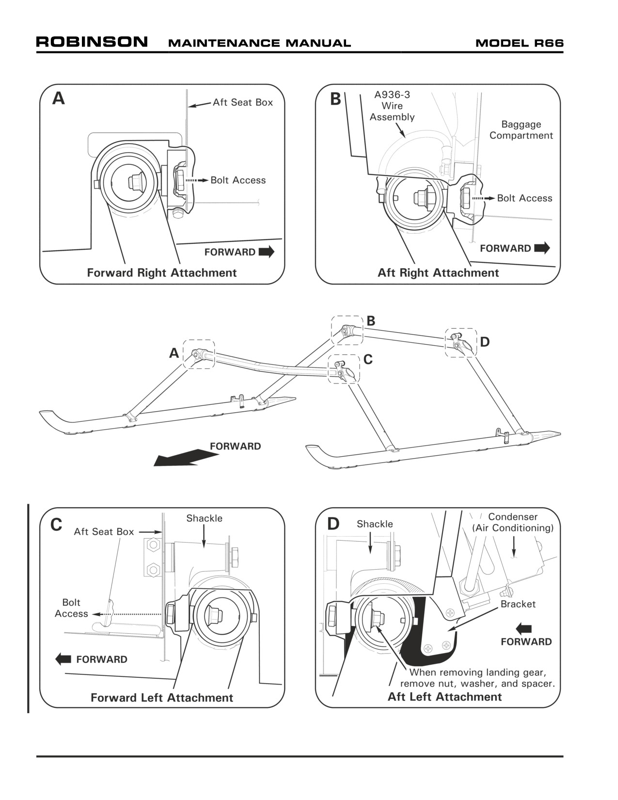
FIGURE 32-1 LANDING GEAR ATTACHMENT
Page 32.2
Chapter 32 Landing Gear
32-10 Landing Gear Assembly (continued)
B.
Installation
Refer to R66 Illustrated Parts Catalog (IPC) Figure 32-1.
WARNING
Landing gear mounting bolts are critical fasteners. See Section
20-30 for torque requirements.
CAUTION
Support landing gear assembly as mounting bolts are installed.
Do not damage forward cross tube hinged inspection cover.
1.
Hoist helicopter per Section 7-20 to required height.
2.
Refer to Figure 32-1. Align mounting bolt (in place) with aft, left landing gear attachment.
Install hardware, special torque fastener per Section 20-33, & torque stripe per Figure
5-1. If air conditioning is installed, install hardware securing G787-3 and G787-4
brackets to condenser support. Verify security.
3.
Insert hardware thru access hole on aft, left seat box forward wall, and thru shackle.
Align mounting bolt with forward, left landing gear attachment. Install hardware, special
torque bolt per Section 20-33, & torque stripe per Figure 5-1.
4.
Insert hardware thru right side access hole on baggage compartment aft wall and aft,
right landing gear attachment. Install hardware, special torque bolt per Section 20-33,
& torque stripe per Figure 5-1.
5.
Insert hardware thru access hole on aft, right seat box forward wall and forward, right
landing gear attachment. Install hardware, special torque bolt per Section 20-33, &
torque stripe per Figure 5-1.
6.
Lower helicopter per Section 7-20. Close cabin aft doors and baggage compartment
door.
7.
Verify surface under terminal is clean and dry and install hardware securing A936-3
(ground) wire assembly to aft, right landing gear attachment. Standard torque screw
per Section 20-32 and torque stripe per Figure 5-1.
8.
Verify rain caps and bonding surfaces are clean and dry. Bond caps to landing gear
assembly using B270-1 sealant. Mix sealant according to manufacturer's instructions.
9.
Refinish landing gear as required per Chapter 20.
10.
When surfaces are dry, install engine cowling per Section 53-21. Refer to Section 6-70;
install G308-2 and two F475-6 cross tube covers. Install fairing assemblies per Section
32-40.
Chapter 32 Landing Gear
Page 32.3
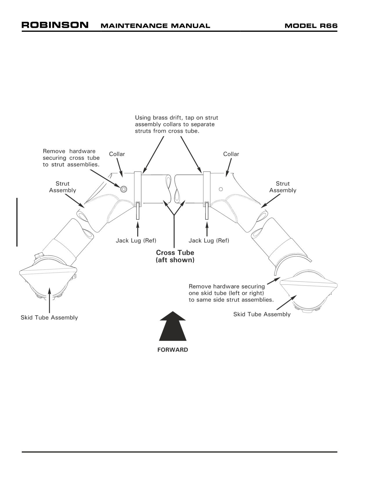
FIGURE 32-2 CROSS TUBE REMOVAL
Page 32.4
Chapter 32 Landing Gear
32-20 Cross Tubes
A. Inspection
For helicopters with F014-1 (standard) landing gear or F014-4 (pop-out float) landing gear,
replace aft cross tube if tail skid height is less than 38 inches from ground when aircraft is
minimally loaded on level pavement.
For helicopters with F014-5 (extended) landing gear, replace aft cross tube if tail skid height
is less than 30 inches from ground when aircraft is minimally loaded on level pavement.
For hard landing inspection, see Section 5-65.
B.
Removal
1. Remove landing gear per Section 32-10.
2. Refer to Figure 32-2. Remove hardware securing one skid tube (left or right) to same
side strut assemblies.
3. Remove hardware securing cross tube (to be replaced) to strut assemblies. Using brass
drift, tap on strut assembly collars to separate struts from cross tube. Do not tap on
jack tabs.
C. Installation
Refer to R66 Illustrated Parts Catalog (IPC) Figure 32-1.
NOTE
When installing A936-3 (ground) wire assembly, verify finish is
removed from surface under wire terminal.
1. Refer to Figure 32-2. Lightly coat mating surfaces of cross tube with zinc-chromate or
epoxy primer using approved materials per Section 20-70. While primer is wet, install
cross tube into strut assemblies and align fastener holes.
2. Install hardware securing cross tube to strut assemblies, standard torque screws per
Section 20-32, and torque stripe per Figure 5-1.
3. Install hardware securing left or right skid tube to strut assemblies, standard torque
bolts per Section 20-32, and torque stripe per Figure 5-1.
4. Install landing gear per Section 32-10.
Chapter 32 Landing Gear
Page 32.5
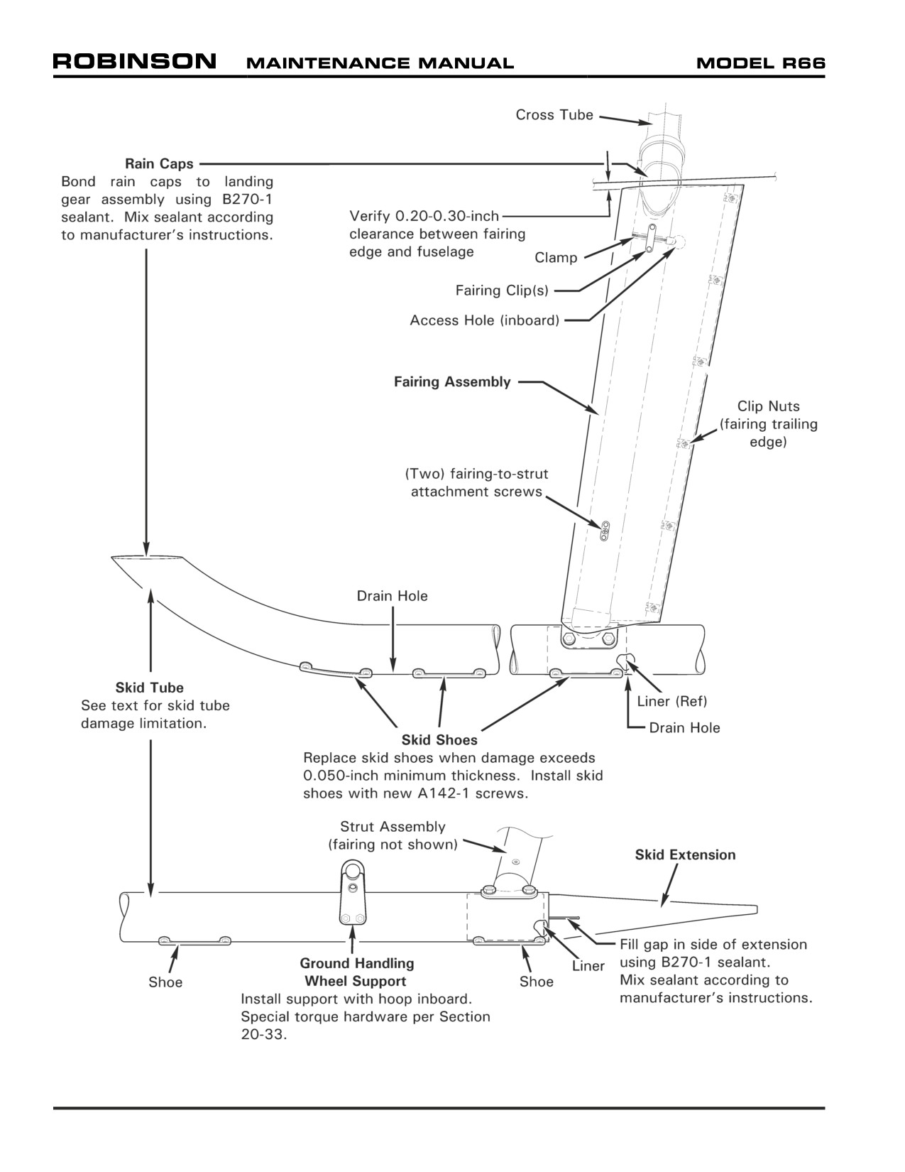
FIGURE 32-3 SKID TUBES AND FAIRINGS
(Strut and skid tube angles exaggerated for clarity)
Page 32.6
Chapter 32 Landing Gear
32-30 Skid Tubes
Refer to R66 Illustrated Parts Catalog (IPC) Figure 32-1.
CAUTION
Minimize personnel movement around raised helicopter. Use
caution when working under raised skid tubes.
A. Inspection
1. Install ground handling wheels per Section 9-11.
2. Pull down on tail rotor gearbox and place blocks under skid tubes, forward of forward
strut assemblies. Skids should be approximately parallel with the ground.
3. Measure damage on left or right skid tube. Replace skid tube if damage exceeds the
following limits:
a.
0.030 inch maximum depth longitudinal scratch (no length limit).
b.
0.030 inch maximum depth and 0.50 inch maximum length circumference scratch.
c.
0.500 inch maximum width flat spot.
4. Measure the thickness of skid tube's skid shoes (five per skid). Replace a skid shoe
per Section 32-31 if damage exceeds 0.050 inch minimum thickness. Repeat steps on
opposite skid tube.
B.
Removal
1. Jack or hoist helicopter per Sections 7-10 or 7-20. Raise skids above ground approximately
4 inches.
2. Refer to Figure 32-3. Remove hardware securing left or right skid tube to same side
strut assemblies.
C. Installation
1. Jack or hoist helicopter per Sections 7-10 or 7-20 to required height.
2. Refer to Figure 32-3. Install hardware securing skid tube to strut assemblies. Standard
torque bolts per Section 20-32 and torque stripe per Figure 5-1.
3. Lower helicopter per Sections 7-10 or 7-20.
Chapter 32 Landing Gear
Page 32.7
32-31 Skid Shoes
Refer to R66 Illustrated Parts Catalog (IPC) Figure 32-1.
A. Inspection
Inspect skid tubes and skid shoes per Section 32-30.
B. Replacement
1. Refer to Figure 32-3. Remove and discard hardware securing skid shoe to skid tube.
Discard a shoe damaged beyond limits in Section 32-30.
2. Install new A142-1 screws to secure skid shoe to skid tube. Standard torque screws
per Section 20-32.
32-32 Skid Extension Replacement
Refer to R66 Illustrated Parts Catalog (IPC) Figure 32-1.
1. Remove skid tube per Section 32-30.
2. Refer to Figure 32-3. Remove and discard hardware securing aft skid shoe to skid tube.
Remove skid extension.
3. Clean interior of skid tube as practical. Install new skid extension and align fastener
holes.
4. Install new A142-1 screws to secure aft skid shoe to skid tube. Standard torque screws
per Section 20-32.
5. Install skid tube per Section 32-30.
6. Fill gap in side of skid extension using B270-1 sealant. Mix sealant according to
manufacturer's instructions.
32-33 Ground Handling Wheel Support Replacement
Refer to R66 Illustrated Parts Catalog (IPC) 32-1.
1. Refer to Figure 32-3. Remove hardware securing support weldment to skid tube and
remove support.
2. Install hardware securing new support weldment to skid tube. Verify correct support
orientation. Special torque hardware per Section 20-33 and torque stripe per Figure 5-1.
Page 32.8
Chapter 32 Landing Gear
32-40 Fairing Assemblies
Refer to R66 Illustrated Parts Catalog (IPC) Figure 32-5.
A. Removal
1. Refer to Figure 32-3. Remove screws securing fairing assembly together at trailing
edge.
2. Remove screws securing fairing assembly to strut assembly. Unscrew clamp through
fairing inboard access hole and remove fairing.
B. Installation
1. Refer to Figure 32-3. Verify fairing assembly clip nuts are installed. Verify clamp
threads through fairing clips, with hex facing inboard access hole.
2. Position fairing assembly on strut assembly and install screws securing fairing to strut.
3. Tighten clamp, and special torque hex through fairing assembly inboard access hole per
Section 20-33.
4. Install screws securing fairing assembly together at trailing edge.
5. Verify 0.20-0.30 inch clearance between fairing assembly edge and fuselage. Remove
and trim fairing as required; reinstall per preceding steps.
32-50 Maintenance
1. Refer to Figure 32-3. Verify drain holes in bottom of skid tubes are free of obstructions
(two per skid, between two forward skid shoes and aft of skid shoe at forward strut
assembly).
2. Refinish landing gear to prevent corrosion per Chapter 20.
3. Inspect skid tubes and skid shoes per Section 32-30, especially following touch-down
autorotations or running take-offs or landings.
4. Verify skid tube and strut assembly rain caps are properly sealed. Replace or re-seal rain
caps per the following:
a. Using putty knife or plastic scraper, cut sealant securing rain cap to landing gear
assembly and remove cap. Remove sealant residue from caps, cross tubes, and/or strut
assemblies. Clean surfaces with solvent.
b. Verify rain caps and bonding surfaces are clean and dry. Bond caps to landing gear
assembly using B270-1 sealant. Mix sealant according to manufacturer's instructions.
Chapter 32 Landing Gear
Page 32.9
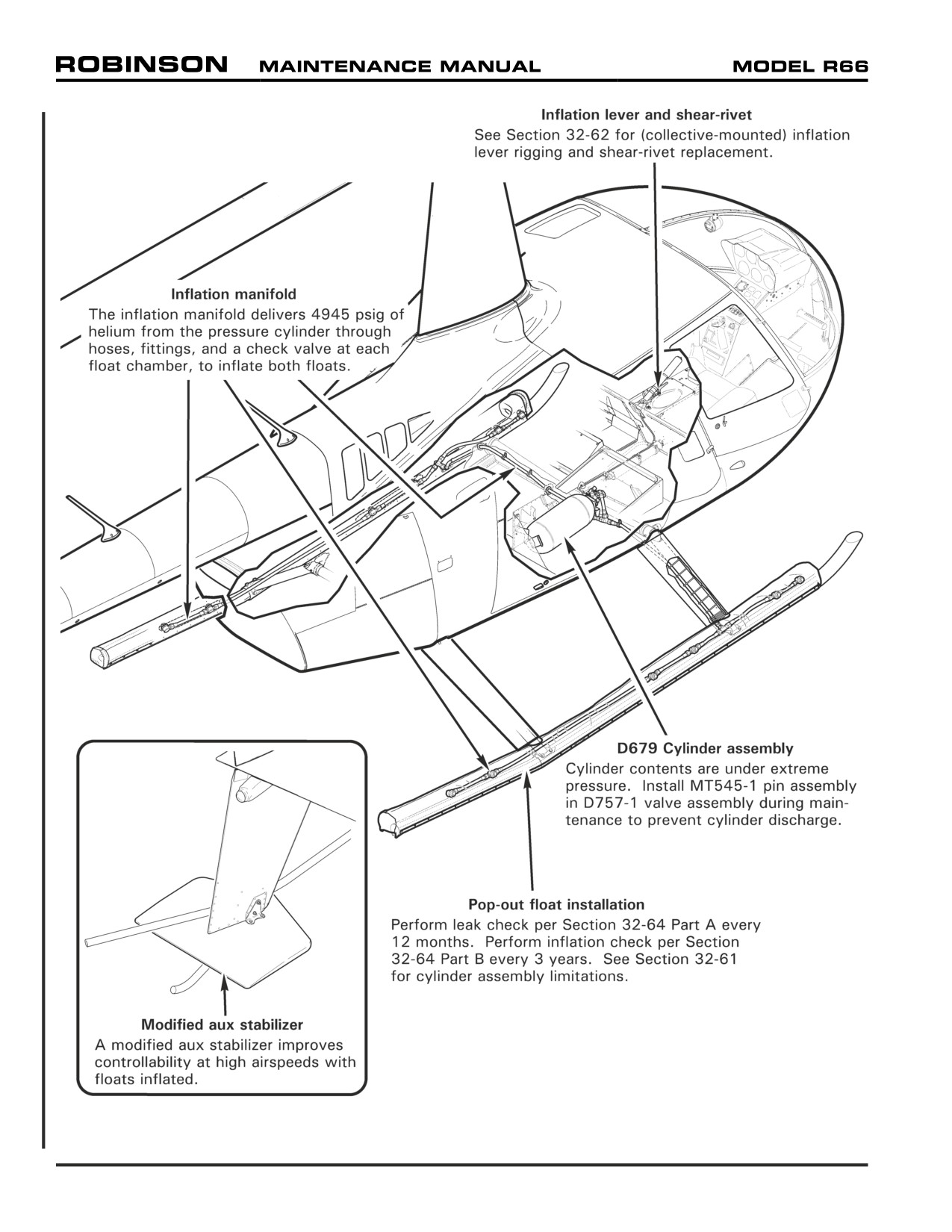
FIGURE 32-4 POP-OUT FLOATS INSTALLATION
Page 32.10
Chapter 32 Landing Gear
32-60 Pop-Out Floats Installation
Pop-out floats are optional equipment for R66 helicopters. The pop-out float installation
includes inflatable floats stowed in protective covers secured to the skid tubes, a pressure
cylinder located in the compartment beneath the right aft seat, an inflation manifold, an inflation
lever located on the pilot’s collective stick, and a modified aux stabilizer.
The valve located on top of the pressure cylinder has a pressure gage, a thermal relief valve
which releases pressure if exposed to excessive heat (281º F), a metal sealing disk, and a
spring-loaded pin.
The red inflation lever on the pilot’s collective stick is equipped with a spring-loaded safety to
prevent inadvertent float inflation. To inflate the floats, the safety is pushed in and rotated
from LOCKED to READY position, then the inflation lever is squeezed with enough force to
shear the aluminum rivet. The spring-loaded pin in the pressure cylinder valve punctures the
metal sealing disk, and 4945 psig (nominal, at 20º C) of helium is released into the inflation
manifold to inflate both floats.
The manifold consists of hoses, fittings, and a check valve at each of the six float chambers
(per float). Each float chamber has a topping valve for manual inflation, and a pressure relief
valve to vent excess internal pressure.
A modified aux stabilizer improves controllability at high airspeeds with floats inflated.
32-61 Cylinder Assembly
Refer to R66 Illustrated Parts Catalog (IPC) Figure 32-7.
NOTE
Cylinders are discharged during float inflation check every 3
years. Cylinder hydrostatic test is required every
5 years.
Cylinder life-limit is 15 years from date of manufacture. To
ensure cylinder limitations are not overflown, returning to
service cylinders with more than 2 years since hydrostatic test
or 12 years since date of manufacture is not recommended.
WARNING
D679 Cylinder contents are under extreme pressure. Install
MT545-1 pin assembly in D757-1 valve assembly during
maintenance to prevent cylinder discharge.
Chapter 32 Landing Gear
Page 32.11
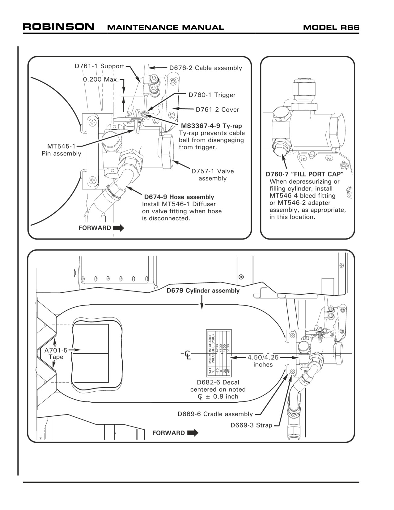
FIGURE 32-5 POP-OUT FLOATS CYLINDER ASSEMBLY
Page 32.12
Chapter 32 Landing Gear
32-61 Cylinder Assembly (continued)
A. Removal
1. Refer to Figure 32-5. Hinge right aft seat assembly forward. Install MT545-1 pin
assembly in D757-1 valve assembly.
2. Disconnect D674-9 hose assembly from valve fitting. Install MT546-1 diffuser on
valve fitting and special torque diffuser to 120 in.-lb. Cap hose to prevent foreign
object contamination.
3. Remove hardware securing D761-2 cover to valve and D761-1 support. Remove
cover.
4. Remove hardware securing D761-1 support to valve. Do not kink cable.
5. Cut and discard MS3367-4-9 ty-rap secured to D760-1 trigger. Disengage D676-2
cable assembly ball from trigger, but do not kink cable.
6. Remove screws securing D669-3 strap to D669-6 cradle assembly and remove strap.
Carefully remove cylinder.
B.
Depressurization
CAUTION
Use appropriate eye and hearing protection. Do not service
cylinder assembly while cylinder is installed in helicopter.
1. Remove cylinder per Section 32-61 Part A. Verify MT545-1 pin assembly and
MT546-1 diffuser are properly installed.
2. Refer to Figure 32-5. Remove D760-7 cap (etched with “FILL PORT”) from valve
assembly. A loud pop may be heard when cap’s seal is broken.
3. In a well-ventilated area, slowly screw MT546-4 bleed fitting assembly into fill-port
until the noise of escaping gas is heard. Screw fitting in or out to adjust flow rate.
Finish bleeding cylinder with bleed fitting fully in. When noise ceases, verify cylinder
pressure gage indicates zero. Remove bleed fitting.
4. Install cap in valve assembly and special torque cap to 40 in.-lb.
5. Evaluate cylinder life and hydrostatic test status.
Chapter 32 Landing Gear
Page 32.13
32-61 Cylinder Assembly (continued)
C. Filling
CAUTION
Use appropriate eye and hearing protection. Do not service
cylinder assembly while cylinder is installed in helicopter.
WARNING
ONLY cylinders labeled “DOT-E 10915-4945” may be refilled.
Cylinders labeled “DOT-E 10915-4500” must be returned to
RHC for exchange/upgrade.
WARNING
Verify D757-1 (gray) valve assembly is engraved with “D758-4”
or has a data plate indicating B900-8 modification.
Filling equipment (pumps, hoses, fittings, etc.) must be rated for 6000 psi minimum
working pressure and be in good condition.
Cylinder temperature and pressure must be kept within safe limits. Monitor pressure gage
and use thermocouple or other appropriate temperature probe to monitor temperature
on face of thermal relief fitting during fill. Do not allow temperature to exceed 50ºC
(122ºF) or pressure to exceed 5500 psig. If limits are approached, stop fill and allow
cylinder to cool and pressure to drop before continuing. Placing cylinder in a water bath
and using slow to moderate fill rates is recommended. If using water bath, keep water
level below valve assembly to avoid water contamination of valve.
1. Evaluate cylinder life and hydrostatic test status.
2. Refer to Figure 32-5. Install MT545-1 pin assembly in D757-1 valve assembly.
Install MT546-1 diffuser on valve fitting and special torque diffuser to 120 in.-lb.
3. Remove D760-7 cap (etched with “FILL PORT”) from valve assembly. A loud pop
may be heard when cap’s seal is broken.
4. Install MT546-2 adapter assembly into fill port and special torque adapter to 40 in.-
lb. Attach fill hose to adapter.
5. Fill with 99.98% minimum purity (industrial grade) helium per chart below:
Ambient Temperature (ºC)
Pressure (psig)
-20
4268
-10
4437
0
4606
10
4776
20
4945
30
5114
40
5283
Page 32.14
Chapter 32 Landing Gear
32-61 Cylinder Assembly (continued)
C. Filling (continued)
6. Allow cylinder and valve to cool to ambient temperature. Top off with helium to
compensate for any pressure loss due to cooling.
7. Remove fill hose and MT546-2 adapter assembly.
8. Remove & discard old o-ring from cap. Lightly coat new MS28778-2 o-ring with
A257-19 lubricant and install o-ring on fill-port cap at base of threads. Install cap in
valve assembly and special torque cap to 40 in.-lb.
D. Installation
WARNING
Verify D757-1 (gray) valve assembly is engraved with “D758-4”
or has a data plate indicating B900-8 modification.
1.
Fill cylinder per Section 32-61 Part C, if not previously accomplished.
2.
Refer to Figure 32-5. Install MT545-1 pin assembly in D757-1 valve assembly.
3.
Hinge right aft seat assembly forward. Verify A701-5 (anti-chafe) tape protects
cylinder where cylinder base contacts cabin structure in three locations. Carefully
position cylinder in D669-6 cradle assembly.
4.
Engage D676-2 cable assembly ball in D760-1 trigger; do not kink cable. Install
MS3367-4-9 ty-rap as shown. Cinch ty-rap until snug without over-tightening, and
trim tip flush with head. Install hardware securing D761-1 support to valve.
5.
Verify cable housing protrudes through clamps on support flush-to-0.200 inch
maximum. Adjust as necessary.
6.
Rotate cylinder as required to minimize cable bending and to ensure clearance with
cabin structure.
7.
Verify D682-6 decal is in specified location. If decal location is incorrect, remove
old decal and install new decal on cylinder. Install screws securing D669-3 strap
to cradle assembly.
8.
Install hardware securing D761-2 cover to valve and D761-1 support.
9.
Remove MT546-1 diffuser, if installed. Connect D674-9 hose assembly to valve
fitting. Orient hose as required to maintain miminum 0.25 inch clearance to cylinder
and adjacent vertical panel. Special torque B-nut per Section 20-33 and torque
stripe per Figure 5-1.
10.
Rig inflation lever and replace shear-rivet per Section 32-62.
Chapter 32 Landing Gear
Page 32.15
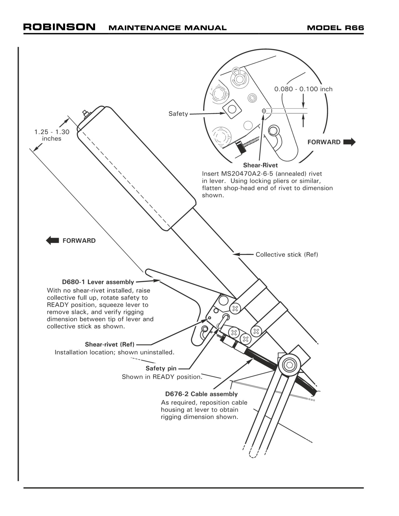
FIGURE 32-6 POP-OUT FLOATS LEVER RIGGING AND SHEAR-RIVET REPLACEMENT
Page 32.16
Chapter 32 Landing Gear
32-62 Lever Rigging and Shear-Rivet Replacement
Refer to R66 Illustrated Parts Catalog (IPC) Figure 32-9.
WARNING
D679 Cylinder contents are under extreme pressure. Install
MT545-1 pin assembly in D757-1 valve assembly during
maintenance to prevent cylinder discharge.
WARNING
Install MS20470A2-6-5 (or MS20470A2-6.5) annealed rivet in
lever assembly or rivet may be too hard to shear.
1.
Install cylinder per Section 32-61 Part D, if not previously accomplished. Install MT545-1
pin assembly in D757-1 valve assembly.
2.
Refer to Figure 32-6. With no shear-rivet installed, raise collective full up, push in and
rotate D680-1 lever assembly safety to READY position, squeeze lever to remove cable
slack, and verify 1.25 - 1.30 in. between tip of lever and collective stick as shown. As
required, reposition D676-2 cable assembly housing at lever to obtain dimension.
3.
Push in and rotate lever safety to LOCKED position. Simultaneously squeeze lever and
verify no preload in cable thru full collective travel.
4.
Refer to Figure 32-6. Insert MS20470A2-6-5 (or MS20470A2-6.5) rivet in lever as
shown. Using locking pliers or similar, flatten shop-head end of rivet to 0.080-0.100 in.
5.
Verify lever safety is in LOCKED position. Remove MT545-1 pin assembly from D757-1
valve assembly.
Chapter 32 Landing Gear
Page 32.17
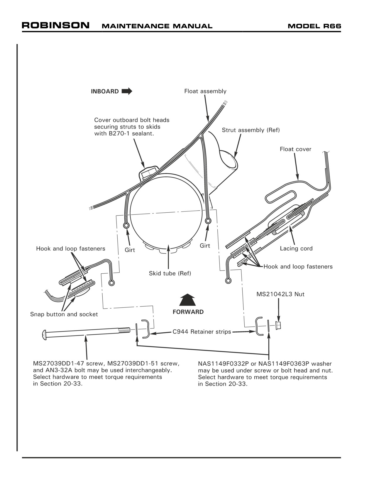
FIGURE 32-7 POP-OUT FLOATS FLOAT INSTALLATION
Page 32.18
Chapter 32 Landing Gear
32-63 Float Installation
Refer to R66 Illustrated Parts Catalog (IPC) Figure 32-11 and 32-17.
WARNING
D679 Cylinder contents are under extreme pressure. Install
MT545-1 pin assembly in D757-1 valve assembly during
maintenance to prevent cylinder discharge.
A. Removal
NOTE
Floats are subject to damage during removal. Remove floats if
necessary for repairs.
1. Refer to Figure 32-5. Hinge right aft seat assembly forward. Install MT545-1 pin
assembly in D757-1 valve assembly.
2. Disconnect D674-12 hose assembly from T-fitting near float. Cap fittings to prevent
foreign object contamination.
3. Refer to Figure 32-7. Detach float cover hook and loop tape inboard of skid and
loosen lacing.
4. Remove hardware securing float to skid tube, and skid extension.
5. Use care when removing C944 retainer strips from girts, and when separating girts
from skid tube and skid extension. Repeat steps for opposite float.
B.
Installation
1. Refer to Figure 32-7. Verify (outboard) bolt heads securing struts to skids are
covered with B270-1 sealant. Apply additional sealant as required.
2. Position deflated float over skid tube and skid extension. Align holes in C944 retainer
strips, float covers, float girts, and skid and install hardware. Special torque nuts per
Section 20-33.
3. Inflate float with filtered, oil-free, dry air to 3.0 psig at topping valves.
4. Remove caps and connect D674-12 hose assembly to T-fitting near float. Special
torque hose B-nut per Section 20-33, apply B270-22 protectant to exposed aluminum
surfaces on hose B-nut and T-fitting, and torque stripe per Figure 5-1. Repeat steps
for opposite float.
5. Pack floats per Section 32-63 Part C.
Chapter 32 Landing Gear
Page 32.19